
Related Manuals for Enterasys Enterasys Diamond Distributed Forwarding Engine 7KR4297-02


Summary of Contents for Enterasys Enterasys Diamond Distributed Forwarding Engine 7KR4297-02
- Page 1 Enterasys Matrix DFE-Diamond Series Hardware Installation Guide 7KR4297-02 7KR4297-04 P/N 9034365-01...
- Page 3 Elektrischer Gefahrenhinweis: Installationen sollten nur durch ausgebildetes und qualifiziertes Personal vorgenommen werden. Enterasys Networks reserves the right to make changes in specifications and other information contained in this document and its web site without prior notice. The reader should in all cases consult Enterasys Networks to determine whether any such changes have been made. The hardware, firmware, or software described in this document is subject to change without notice. IN NO EVENT SHALL ENTERASYS NETWORKS BE LIABLE FOR ANY INCIDENTAL, INDIRECT, SPECIAL, OR CONSEQUENTIAL DAMAGES WHATSOEVER (INCLUDING BUT NOT LIMITED TO LOST PROFITS) ARISING OUT OF OR RELATED TO THIS DOCUMENT, WEB SITE, OR THE INFORMATION CONTAINED IN THEM, EVEN IF ENTERASYS NETWORKS HAS BEEN ADVISED OF, KNEW OF, OR SHOULD HAVE KNOWN OF, THE POSSIBILITY OF SUCH DAMAGES. Enterasys Networks, Inc. 50 Minuteman Road Andover, MA 01810 © 2008 Enterasys Networks, Inc. All rights reserved. Part Number: 9034365‐01 February 2008 ENTERASYS, ENTERASYS NETWORKS, ENTERASYS MATRIX, ENTERASYS NETSIGHT, LANVIEW, WEBVIEW, and any logos associated therewith, are trademarks or registered trademarks of Enterasys Networks, Inc., in the United States and other countries. All other product names mentioned in this manual may be trademarks or registered trademarks of their respective companies. Documentation URL: http://www.enterasys.com/support/manuals Documentacion URL: http://www.enterasys.com/support/manuals Dokumentation im Internet: http://www.enterasys.com/support/manuals...
-
Page 4: Regulatory Compliance Information
Regulatory Compliance Information Federal Communications Commission (FCC) Notice This device complies with Part 15 of the FCC rules. Operation is subject to the following two conditions: (1) this device may not cause harmful interference, and (2) this device must accept any interference received, including interference that may cause undesired operation. NOTE: This equipment has been tested and found to comply with the limits for a class A digital device, pursuant to Part 15 of the FCC rules. These limits are designed to provide reasonable protection against harmful interference when the equipment is operated in a commercial environment. This equipment uses, generates, and can radiate radio frequency energy and if not installed in accordance with the operator’s manual, may cause harmful interference to radio communications. Operation of this equipment in a residential area is likely to cause interference in which case the user will be required to correct the interference at his own expense. WARNING: Changes or modifications made to this device which are not expressly approved by the party responsible for compliance could void the user’s authority to operate the equipment. Industry Canada Notice This digital apparatus does not exceed the class A limits for radio noise emissions from digital apparatus set out in the Radio Interference Regulations of the Canadian Department of Communications. Le présent appareil numérique n’émet pas de bruits radioélectriques dépassant les limites applicables aux appareils numériques de la class A prescrites dans le Règlement sur le brouillage radioélectrique édicté par le ministère des Communications du Canada. Class A ITE Notice WARNING: This is a Class A product. In a domestic environment this product may cause radio interference in which case the user may be required to take adequate measures. Clase A. Aviso de ITE ADVERTENCIA: Este es un producto de Clase A. En un ambiente doméstico este producto puede causar interferencia de radio ... -
Page 5: Hazardous Substances
This product complies with the following: 47 CFR Parts 2 and 15, CSA C108.8, 2004/108/EC, EN 55022, EN 61000‐3‐2, EN 61000‐3‐3, EN 55024, AS/NZS CISPR 22, VCCI V‐3. Este producto de Enterasys cumple con lo siguiente: 47 CFR Partes 2 y 15, CSA C108.8, 2004/108/EC, EN 55022, EN 55024, EN 61000‐3‐2, EN 61000‐3‐3, AS/NZS CISPR 22, VCCI V‐3. Elektro- magnetische Kompatibilität ( EMC ) Dieses Produkt entspricht den folgenden Richtlinien: 47 CFR Parts 2 and 15, CSA C108.8, 2004/108/EC, EN 55022, EN 61000‐3‐2, EN 61000‐3‐3, EN 55024, AS/NZS CISPR 22, VCCI V‐3. This product complies with the requirements of European Directive, 2002/95/EC, Restriction of Hazardous Substances (RoHS) in Electrical and Electronic Equipment. European Waste Electrical and Electronic Equipment (WEEE) Notice In accordance with Directive 2002/96/EC of the European Parliament on waste electrical and electronic equipment (WEEE): The symbol above indicates that separate collection of electrical and electronic equipment is required and that this product was placed on the European market after August 13, 2005, the date of enforcement for Directive 2002/96/EC. When this product has reached the end of its serviceable life, it cannot be disposed of as unsorted municipal waste. It must be collected and treated separately. It has been determined by the European Parliament that there are potential negative effects on the environment and human health as a result of the presence of hazardous substances in electrical and electronic equipment. It is the users’ responsibility to utilize the available collection system to ensure WEEE is properly treated. For information about the available collection system, please go to www.enterasys.com/support Customer Support at 353 61 705586 (Ireland). Electromagnetic Compatibility (EMC) Compatibilidad Electromágnetica (EMC) Hazardous Substances or contact Enterasys ... - Page 6 Supplement to Product Instructions (Parts) (Metal Parts) Circuit Modules) Cables & Cable Assemblies) (Plastic and Polymeric parts) Circuit Breakers) Indicates that the concentration of the hazardous substance in all homogeneous materials in the parts is below the relevant threshold of the SJ/T 11363-2006 standard. Indicates that the concentration of the hazardous substance of at least one of all homogeneous materials in the parts is above the relevant threshold of the SJ/T 11363-2006 standard.
-
Page 7: Safety Information
VCCI Notice This is a class A product based on the standard of the Voluntary Control Council for Interference by Information Technology Equipment (VCCI). If this equipment is used in a domestic environment, radio disturbance may arise. When such trouble occurs, the user may be required to take corrective actions. BSMI EMC Statement — Taiwan This is a class A product. In a domestic environment this product may cause radio interference in which case the user may be required to take adequate measures. Safety Information Class 1 Laser Transceivers The single mode interface modules use Class 1 laser transceivers. Read the following safety information before installing or operating these modules. The Class 1 laser transceivers use an optical feedback loop to maintain Class 1 operation limits. This control loop eliminates the need for maintenance checks or adjustments. The output is factory set, and does not allow any user adjustment. Class 1 Laser ... -
Page 8: Declaration Of Conformity
Application of Council Directive(s): 2004/108/EC Manufacturer’s Name: Enterasys Networks, Inc. Manufacturer’s Address: 50 Minuteman Road European Representative Address: Enterasys Networks, Ltd. Conformance to Directive(s)/Product Standards: EC Directive 2004/108/EC Equipment Type/Environment: Networking Equipment, for use in a Commercial Enterasys Networks, Inc. declares that the equipment packaged with this notice conforms to the above directives. Enterasys Networks, Inc. Firmware License Agreement BEFORE OPENING OR UTILIZING THE ENCLOSED PRODUCT, CAREFULLY READ THIS LICENSE AGREEMENT. This document is an agreement (“Agreement”) between the end user (“You”) and Enterasys Networks, Inc., on behalf of itself and its Affiliates (as hereinafter defined) (“Enterasys”) that sets forth Your rights and obligations with respect to the Enterasys software program/firmware (including any accompanying documentation, hardware or media) (“Program”) in the package and prevails over any additional, conflicting or inconsistent terms and conditions appearing on any purchase order or other ... - Page 9 RESTRICTIONS. Except as otherwise authorized in writing by Enterasys, You may not, nor may You permit any third party to: (a) Reverse engineer, decompile, disassemble or modify the Program, in whole or in part, including for reasons of error correction or interoperability, except to the extent expressly permitted by applicable law and to the extent the parties shall not be permitted by that applicable law, such rights are expressly excluded. Information necessary to achieve interoperability or correct errors is available from Enterasys upon request and upon payment of Enterasys’ applicable fee. (b) Incorporate the Program in whole or in part, in any other product or create derivative works based on the Program, in whole or in part. (c) Publish, disclose, copy reproduce or transmit the Program, in whole or in part. (d) Assign, sell, license, sublicense, rent, lease, encumber by way of security interest, pledge or otherwise transfer the Program, in whole or in part. (e) Remove any copyright, trademark, proprietary rights, disclaimer or warning notice included on or embedded in any part of the Program. APPLICABLE LAW. This Agreement shall be interpreted and governed under the laws and in the state and federal courts of the Commonwealth of Massachusetts without regard to its conflicts of laws provisions. You accept the personal jurisdiction and venue of the Commonwealth of Massachusetts courts. None of the 1980 United Nations Convention on the Limitation Period in the International Sale of Goods, and the Uniform Computer Information Transactions Act shall apply to this Agreement. EXPORT RESTRICTIONS. You understand that Enterasys and its Affiliates are subject to regulation by agencies of the U.S. Government, including the U.S. Department of Commerce, which prohibit export or diversion of certain technical products to certain countries, unless a license to export the product is obtained from the U.S. Government or an exception from obtaining such license may be relied upon by the exporting party. If the Program is exported from the United States pursuant to the License Exception CIV under the U.S. Export Administration Regulations, You agree that You are a civil end user of the Program and agree that You will use the Program for civil end uses only and not for military purposes. If the Program is exported from the United States pursuant to the License Exception TSR under the U.S. Export Administration Regulations, in addition to the restriction on transfer set forth in Section 1 or 2 of this Agreement, You agree not to (i) reexport or release the Program, the source code for the Program or technology to a national of a country in Country Groups D:1 or E:2 (Albania, Armenia, Azerbaijan, Belarus, Cambodia, Cuba, Georgia, Iraq, Kazakhstan, Laos, Libya, Macau, Moldova, Mongolia, North Korea, the People’s Republic of China, Russia, Tajikistan, Turkmenistan, Ukraine, Uzbekistan, Vietnam, or such other countries as may be designated by the United States Government), (ii) export to Country Groups D:1 or E:2 (as defined herein) the direct product of the Program or the technology, if such foreign produced direct product is subject to national security controls as identified on the U.S. Commerce Control List, or (iii) if the direct product of the technology is a ...
- Page 10 LIMITATION OF LIABILITY. IN NO EVENT SHALL ENTERASYS OR ITS SUPPLIERS BE LIABLE FOR ANY DAMAGES WHATSOEVER (INCLUDING, WITHOUT LIMITATION, DAMAGES FOR LOSS OF BUSINESS, PROFITS, BUSINESS INTERRUPTION, LOSS OF BUSINESS INFORMATION, SPECIAL, INCIDENTAL, CONSEQUENTIAL, OR RELIANCE DAMAGES, OR OTHER LOSS) ARISING OUT OF THE USE OR INABILITY TO USE THE PROGRAM, EVEN IF ENTERASYS HAS BEEN ADVISED OF THE POSSIBILITY OF SUCH DAMAGES. THIS FOREGOING LIMITATION SHALL APPLY REGARDLESS OF THE CAUSE OF ACTION UNDER WHICH DAMAGES ARE SOUGHT. THE CUMULATIVE LIABILITY OF ENTERASYS TO YOU FOR ALL CLAIMS RELATING TO THE PROGRAM, IN CONTRACT, TORT OR OTHERWISE, SHALL NOT EXCEED THE TOTAL AMOUNT OF FEES PAID TO ENTERASYS BY YOU FOR THE RIGHTS GRANTED HEREIN. AUDIT RIGHTS. You hereby acknowledge that the intellectual property rights associated with the Program are of critical value to Enterasys, and, accordingly, You hereby agree to maintain complete books, records and accounts showing (i) license fees due and paid, and (ii) the use, copying and deployment of the Program. You also grant to Enterasys and its authorized representatives, upon reasonable notice, the right to audit and examine during Your normal business hours, Your books, records, accounts and hardware devices upon which the Program may be deployed to verify compliance with this Agreement, including the verification of the license fees due and paid Enterasys and the use, copying and deployment of the Program. Enterasys’ right of examination shall be exercised reasonably, in good faith and in a manner calculated to not unreasonably interfere with Your business. In the event such audit discovers non‐compliance with this Agreement, including copies of the Program made, used or deployed in breach of this Agreement, You shall promptly pay to Enterasys the appropriate license fees. Enterasys reserves the right, to be exercised in its sole discretion and without prior notice, to terminate this license, effective immediately, for failure to comply with this Agreement. Upon any such termination, You shall immediately cease all use of the Program and shall return to Enterasys the Program and all copies of the Program. OWNERSHIP. This is a license agreement and not an agreement for sale. You acknowledge and agree that the Program constitutes trade secrets and/or copyrighted material of Enterasys and/or its suppliers. You agree to implement reasonable security measures to protect such trade secrets and copyrighted material. All right, title and interest in and to the Program shall remain with Enterasys and/or its suppliers. All rights not specifically granted to You shall be reserved to Enterasys. 10. ENFORCEMENT. You acknowledge and agree that any breach of Sections 2, 4, or 9 of this Agreement by You may cause Enterasys irreparable damage for which recovery of money damages would be inadequate, and that Enterasys may be entitled to seek timely injunctive relief to protect Enterasys’ rights under this Agreement in addition to any and all remedies available at law. 11. ASSIGNMENT. You may not assign, transfer or sublicense this Agreement or any of Your rights or obligations under this Agreement, except that You may assign this Agreement to any person or entity which acquires substantially all of Your stock assets. Enterasys may assign this Agreement in its sole discretion. This Agreement shall be binding upon and inure to the benefit of the parties, their legal representatives, permitted transferees, successors and assigns as permitted by this Agreement. Any attempted assignment, transfer or sublicense in violation of the terms of this Agreement shall be void and a breach of this ...
-
Page 11: Table Of Contents
7KR4297-04 ... 1-2 XFP 10GBASE-LR, -ER, -LX4, and -SR PHY Management ... 1-3 Switch Configuration Using WebView ... 1-3 Switch Configuration Using CLI Commands ... 1-3 Secure Networks Policy Support ... 1-4 Standards Compatibility ... 1-4 LANVIEW Diagnostic LEDs ... 1-4 Chapter 2: Network Requirements XFP 10-Gigabit Ethernet ... - Page 12 Troubleshooting Checklist ... 4-4 Overview of DFE-Diamond Module Shutdown Procedure ... 4-5 Recommended Shutdown Procedure Using OFFLINE/RESET Switch ... 4-6 Last Resort Shutdown Procedure Using OFFLINE/RESET Switch ... 4-7 Appendix A: Specifications DFE-Diamond Module Specifications ...A-1 10-Gigabit Ethernet Transceiver Specifications (XFP) ...A-2 COM Port Pinout Assignments ...A-3...
-
Page 13: About This Guide
This guide provides an overview, installation and troubleshooting instructions, and specifications for the Enterasys Matrix interface modules. For information about the CLI (Command Line Interface) set of commands used to configure and manage the DFE‐Diamond modules, refer to the Enterasys Matrix™ DFE‐Diamond/Platinum Series Configuration Guide. Note: In this guide, the following terms are used: • DFE refers to Distributed Forwarding Engine series of modules. • Unless otherwise noted, DFE module refers to both the 7KR4297-02 and 7KR4297-04 modules. • XFP refers to a 10-Gbps physical interface module inserted into a DFE module NEM slot. •... -
Page 14: How To Use This Guide
For... An overview of the DFE module and instructions to obtain technical support from Enterasys Networks Network requirements that must be met before installing the DFE module Instructions to install the DFE module hardware and optional XFP interface module... -
Page 15: Document Conventions
Document Conventions The following typographical conventions and icons are used in this document. blue type Indicates a hypertext link. When reading this document online, click the text in blue to go to the referenced figure, table, or section. Lowercase x Indicates the general use of an alphanumeric character (for example, 6x1xx, the x’s indicate a combination of numbers or letters). -
Page 16: Getting Help
The device history (for example, if you have returned the device before, or if this is a recurring problem) • Any previous Return Material Authorization (RMA) numbers xiv About This Guide www.enterasys.com/support/ 1-800-872-8440 (toll-free in U.S. and Canada) or 1-978-684-1000 For the Enterasys Networks Support toll-free number in your country: www.enterasys.com/support/ support@enterasys.com To expedite your message, please type [SWITCHING] in the subject line. -
Page 17: Overview Of Matrix Dfe-Diamond Module Capabilities
This chapter provides an overview of the Matrix DFE‐Diamond 7KR4297‐02 and 7KR4297‐04 modules and optional XFP 10‐Gbps physical interface module. Note: Unless otherwise noted the term “DFE module” refers to both the 7KR4297-02 and 7KR4297-04 modules. For information about... Overview of Matrix DFE-Diamond Module Capabilities The DFE-Diamond 7KR4297-02 and 7KR4297-04 Modules Management Secure Networks Policy Support Standards Compatibility LANVIEW Diagnostic LEDs Overview of Matrix DFE-Diamond Module Capabilities The Platinum Distributed Forwarding Engine (DFE) is Enterasys Networks’ next generation of ... -
Page 18: The Dfe-Diamond 7Kr4297-02 And 7Kr4297-04 Modules
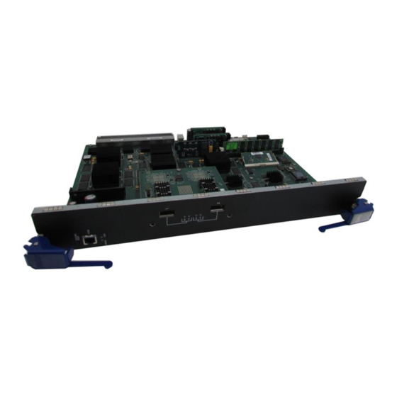
2 CPU LED 3 XFP option slot 1 4 TX (transmit) & RX (receive) LEDs 7KR4297-04 The 7KR4297‐04 DFE‐module has four 10‐Gbps Ethernet port slots on the front panel that can support up to four 10‐Gbps XFP PHYs for high speed uplinks from the chassis DFE Ethernet switch system. With four 10‐Gbps PHYs installed in the 7KR4297‐04, a shared uplink of up to 40 Gbps can be provided from the DFE switching system to two network edge connections from a Matrix E7, Matrix N7, Matrix N5, Matrix N3, or Matrix N1 chassis to a core data center. The DFE module ports can be configured to control traffic by limiting the rate of traffic accepted into the module and prioritizing traffic to expedite the flow of higher priority traffic through the module. The 7KR4297‐04 DFE module can be installed in a Matrix E7, Matrix N7, Matrix N5, Matrix N3, or Matrix N1 chassis, but only supports FTM2 data backplane interconnections in the Matrix E7 chassis. 1-2 Introduction 1‐2, as well as the optional XFP physical interfaces (PHYs). For 5 XFP option slot 2 6 OFFLINE/RESET switch 7 MGMT LED... -
Page 19: Xfp 10Gbase-Lr, -Er, -Lx4, And -Sr Phy
4 TX (transmit) & RX (receive) LEDs 5 XFP option slot 2 XFP 10GBASE-LR, -ER, -LX4, and -SR PHY The LAN XFP PHYs (physical interfaces) provide inexpensive, high‐speed Ethernet connectivity. These PHYs provide network managers the ability to use 10‐Gigabit Ethernet technologies to provide high‐speed, local backbone interconnections between large capacity switches. As demand for bandwidth increases, network administrators can deploy 10‐Gigabit Ethernet throughout the entire network to improve server farm, backbone, and campus‐wide connectivity. Management Management of the module can be either in‐band or out‐of‐band. In‐band remote management is possible using Telnet, Enterasys Networks’ NetSight application. Out‐of‐band management is provided through the RJ45 COM (Communication) port on the front panel using a VT100 terminal or a VT100 terminal emulator. Switch Configuration Using WebView Enterasys Networks’ HTTP‐based Web management application (WebView) is an intuitive web tool for simple management tasks. Switch Configuration Using CLI Commands The CLI commands enable you to perform more complete switch configuration management tasks. For CLI command set information and how to configure the module, refer to the Enterasys Matrix ... -
Page 20: Secure Networks Policy Support
Secure Networks Policy Support Secure Networks Policy Support Policy Enabled Networking manages the allocation of networking infrastructure resources in a secure and effective manner. Using Secure Networks Policy, an IT Administrator can predictably assign appropriate resources to the Users, Applications, and Services that use the network; while blocking or containing access for inappropriate or potentially dangerous network traffic. Using this technology it is possible, for the first time, to align IT services with the needs of specific users and applications, and to leverage the network as a key component of the organization’s security strategy. The Secure Networks Policy Architecture consists of 3 components: Classification Rules, Network Services, and Behavioral Profiles. These are defined as follows: • Classification Rules determine how specific traffic flows (identified by Layer 2, Layer 3, and Layer 4 information in the data packet) are treated by each Switch or Router. In general, Classification Rules are applied to the networking infrastructure at the network edge/ingress point. • Network Services are logical groups of Classification Rules that identify specific networked applications or services. Users may be permitted or denied access to these services based on their role within the organization. Priority and bandwidth rate limiting may also be controlled using Network Services. • Behavioral Profiles (or roles) are used to assign Network Services to groups of users who share common needs–for example Executive Managers, Human Resources Personnel, or Guest Users. Access, resources, and security restrictions are applied as appropriate to each Behavioral Profile. A variety of authentication methods including 802.1X, EAP‐TLS, EAP‐ TTLS, and PEAP may be used to classify and authorize each individual user; and the IT Administrator may also define a Behavioral Profile to apply in the absence of an authentication framework. Standards Compatibility The DFE‐Diamond modules are fully compliant with the IEEE 802.3‐2002, 802.3ae‐2002, 802.1D‐1998, and 802.1Q‐1998 standards. The DFE‐Diamond module provides IEEE 802.1D‐1998 Spanning Tree Algorithm (STA) support to enhance the overall reliability of the network and ... -
Page 21: Chapter 2: Network Requirements
Module Placement in a Matrix E7 Chassis The network installation must meet the requirements to ensure satisfactory performance of this equipment. Failure to do so will produce poor network performance. Note: The Enterasys Matrix DFE-Diamond/Platinum Series Configuration Guide, referred to in the following sections, can be found on the Enterasys Networks World Wide Web site: http://www.enterasys.com/support/manuals XFP 10-Gigabit Ethernet There are two optional 10‐Gigabit interface port slots on the 7KR4297‐02 and four optional 10‐ Gigabit interface port slots on the 7KR4297‐04 that can support various optional XFP 10‐Gigabit ... -
Page 22: Module Placement In A Matrix E7 Chassis
Module Placement in a Matrix E7 Chassis The uplinks have one fiber‐optic interface with an LC connector. Depending on the XFP and fiber‐ optic cable used, the signal can be driven to a maximum distance of 33 m (108 ft) to 40 kilometers (24.85 miles). The device at the other end of the fiber optic connection must be a standards‐compliant product with a matching XFP interface. Module Placement in a Matrix E7 Chassis If you want to mix 6x1xxx, 6x2xxx, 6x3xxx, and 7x4xxx series modules in the same Matrix E7chassis, it is necessary to have a DFE‐Diamond bridging module installed, and follow the module placement rules described in “Backplane Connections and Installation Rules” on page 3‐3 to successfully bridge data traffic to some or all modules in the chassis. 2-2 Network Requirements... -
Page 23: Chapter 3: Installation
Electrical Hazard: Only qualified personnel should perform installation procedures. Riesgo Electrico: Solamente personal calificado debe realizar procedimientos de instalacion. Elektrischer Gefahrenhinweis: Installationen sollten nur durch ausgebildetes und qualifiziertes Personal vorgenommen werden. Read the Release Notes associated with the DFE-Diamond module to check for any exceptions to the supported features and operation documented in this guide. -
Page 24: Unpacking The Dfe-Diamond Module
Table 3-1 Carton Contents Item 7KR4297-02 or 7KR4297-04 DFE-Diamond module Customer Release Notes Remove the tape seal on the non‐conductive bag to remove the DFE‐Diamond module. Perform a visual inspection of the DFE‐Diamond module for any signs of physical damage. Contact Enterasys Networks if there are any signs of damage. Refer to “Getting Help” on page xiv for details. Installing an Optional XFP Module This section describes how to install an XFP module. For the XFP specifications, refer to Appendix Caution: Carefully follow the instructions in this manual to avoid damaging the XFP module and DFE module. -
Page 25: Backplane Connections And Installation Rules
Figure 3-1 Installing an XFP 1 XFP module Removing an XFP Module To remove an XFP from the module port, refer back to Figure Caution: The XFP module and DFE module are sensitive to static discharges. Use an antistatic wrist strap and observe all static precautions during this procedure. Failure to do so can result in damage to the XFP module and DFE module. -
Page 26: Module Placement And Rules
Backplane Connections and Installation Rules The DFE FTM bridging modules have a connection to both FTM1 and FTM2 backplanes, which enables them to switch frames between the two backplanes and all modules in the 6C107 chassis. However, the older first (6x1xx), second (6x2xx), and third (6x3xx) generation modules are still managed using their own Local Management and are not subject to management by the DFE‐Diamond module management entity. The Matrix N3 (7C103) and Matrix N7 (7C107) chassis have only FTM2 connections and support only DFE‐Diamond modules. Module Placement and Rules The DFE series modules can be installed in a Matrix E7, Matrix N1, Matrix N3, Matrix N5, or Matrix N7 chassis. When installing the modules into one of these chassis, make sure to consider the following placement rules for the appropriate chassis and module mix. Matrix N3 Chassis, Module Placement The Matrix N3 chassis slots 1 through 3 will support only DFE‐Diamond modules. Rule: There are no particular rules for installing DFE‐Diamond modules into a Matrix N3 chassis. Matrix N7 Chassis, Module Placement The Matrix N7 chassis slots 1 through 7 will support only DFE‐Diamond modules. - Page 27 Example 2 (Figure 3-1, Shows the chassis fully populated with third generation modules (6x3xx). These modules can also be installed in any available chassis slot in the Matrix E7 chassis, but operate as individual modules with separate IP addresses. Each module is configured using Local Management. Rule: The 6x3xx modules can be installed in any available chassis slot in the Matrix E7 chassis. Example 3 (Figure 3-1, C) Shows chassis slots 1 through 5 populated with first and second generation modules (6x1xx and 6x2xx). If a 6x1xx or 6x2xx series module is installed in slot 6 or 7, it will operate in standalone mode (no backplane connectivity). Like the 6x3xx modules, the 6x1xx and 6x2xx modules operate as individual modules with separate IP addresses, and each one is configured using Local Management. Rule: The 6x1xx and 6x2xx modules can communicate with each other when they are installed in chassis slots 1 through 5 in the Matrix E7 chassis. If installed in slot 6 or 7, they operate in standalone mode. Example 4 (Figure 3-1, Shows chassis slots 1 through 5 populated with a mix of 6x1xx, 6x2xx, and 6x3xx modules and only third generation modules in slots 6 and 7. In this module arrangement, the 6x3xx module provides a proxy bridge, which enables the 6x1xx and 6x2xx modules to communicate with 6x3xx modules in slot 6 or 7. If more than one 6x3xx module is installed in slots 1 to 5, the module in the lowest numbered slot performs the proxy function for slots 6 and 7. Therefore, if a 6x3xx module is already performing the proxy function, and another 6x3xx module is inserted into a lower numbered slot, connectivity will be temporarily interrupted, as the new board takes over the proxy function. When a 6x3xx module in a lower numbered slot is removed, and there is a 6x3xx module in a higher numbered slot, communication is not interrupted. For Local Management, plugging the Local Management connection into the 6x3xx modules will allow management connections to all 6x1xx, 6x2xx, and 6x3xx modules. If the Local Management connection is to a 6x1xx or 6x2xx board, only the modules in the first five slots will be recognized by the management client. Rule: There must be at least one 6x3xx module in slots 1 through 5 to enable communications between the 6x1xx, 6x2xx, and 6x3xx modules.
-
Page 28: Installing Module Into Matrix E7 Or Matrix N7 Chassis
Installing Module into Matrix E7 or Matrix N7 Chassis Example 6 (Figure The module arrangement in this example is similar to the one shown in Figure described in Example 5. The only difference is that a DFE‐Diamond bridging module is installed in slot 2, enabling all modules to communicate with each other. Rule: In this example, the 7H4382‐49 DFE‐Diamond bridging module serves as both the FTM1‐to‐ FTM2 bridge and the five‐to‐seven slot proxy bridge. The 6x3xx does not serve as a proxy bridge in this configuration because the 7H4382‐49 is in a slot with a lower number. Installing Module into Matrix E7 or Matrix N7 Chassis Caution: Failure to observe static safety precautions could cause damage to the module. Follow static safety handling rules and wear the antistatic wrist strap. - Page 29 Installation To install the module, refer to Figure Caution: To prevent damaging the backplane connectors in the following step, take care that the module slides in straight and properly engages the backplane connectors. Ensure that the top lever lines up with the desired slot number located on the front panel of the chassis.
-
Page 30: Installing Module Into Matrix E7 Or Matrix N7 Chassis
Installing Module into Matrix E7 or Matrix N7 Chassis Figure 3-2 Installing Module into Matrix E7 or Matrix N7 Chassis 1 Card guides 2 Slot number 6 (left-most slot is 1) 3 Module 4 Metal back panel 3-8 Installation 5 Upper/lower locking tabs (in proper open position) 6 Upper/lower locking tab (in closed position) 7 Backplane connectors - Top two connectors (power and FTM2) -
Page 31: Installing Module Into Matrix N3 Chassis
Installing Module into Matrix N3 Chassis Caution: Failure to observe static safety precautions could cause damage to the DFE-Diamond module. Follow static safety handling rules and wear the antistatic wrist strap. Do not cut the non-conductive bag to remove the DFE-Diamond module. Sharp objects contacting the board or components can cause damage. -
Page 32: Connecting To The Network
Connecting to the Network Connecting to the Network Note: If the DFE-Diamond module is being installed in a network using Link Aggregation, there are rules concerning the network cable and port configurations that must be followed for Link Aggregation to operate properly. Before connecting the cables, refer to the Enterasys Matrix DFE- Diamond/Platinum Series Configuration Guide for the configuration information. -
Page 33: Connecting To Com Port For Local Management
Verify that a link exists by checking that the port RX LED is on (flashing amber, blinking green, or solid green). If the RX LED is off, there is no link. Perform the following steps until it is on: Check that the device at the other end of the link has power turned on and is compatible. b. Verify proper crossover of fiber strands between the port on the module and the fiber‐ optic device at the other end of the fiber‐optic link segment. Verify that the fiber‐optic cable meets the specifications outlined in Appendix installed Ethernet expansion module. To remove the SC cable connector from the interface port, carefully pull the connector out of the port. It may need to be loosened by gently moving from side to side to release the latching keys. If a link has not been established, refer to Chapter “Getting Help” on page xiv for details on contacting Enterasys Networks for support. Connecting to COM Port for Local Management This section describes how to install a UTP straight‐cable with RJ45 connectors and optional adapters to connect a PC, a VT series terminal, or a modem to an Enterasys Networks module to access Local Management. This section also provides the pinout assignments of the adapters. What Is Needed The following is a list of the user‐supplied parts that may be needed depending on the connection: • RJ45‐to‐DB9 female adapter • UTP straight‐cable with RJ45 connectors Connecting to COM Port for Local Management... -
Page 34: Connecting To An Ibm Pc Or Compatible Device
RJ45‐to‐DB25 male adapter With a UTP straight‐cable with RJ45 connectors and RJ45‐to‐DB9 adapter, you can connect products equipped with an RJ45 COM port to an IBM or compatible PC running a VT series emulation software package. With a UTP straight‐cable and an optional RJ45‐to‐DB25 female adapter, you can connect products equipped with an RJ45 COM port to a VT series terminal or VT type terminals running emulation programs for the VT series. With a UTP straight‐cable and an optional RJ45‐to‐DB25 male adapter, you can connect products equipped with an RJ45 COM port to a Hayes compatible modem that supports 9600 baud. Connecting to an IBM PC or Compatible Device To connect an IBM PC or compatible device, running the VT terminal emulation, to an Enterasys Networks module COM port (Figure Connect the RJ45 connector at one end of the UTP straight‐cable to the communications COM port on the Enterasys Networks module. (The COM port is also known as a Console port.) Plug the RJ45 connector at the other end of the UTP straight‐cable into an optional RJ45‐to‐ DB9 female adapter. Connect the RJ45‐to‐DB9 adapter to the communications port on the IBM PC or compatible device. Turn on the PC and configure your VT emulation package with the following parameters: Parameter Mode Transmit Bits Parity Stop Bit When these parameters are set, the Local Management password screen will display. Refer to the appropriate Enterasys Matrix DFE‐Diamond/Platinum Series Configuration Guide for further information. 3-12 Installation 3‐5), proceed as follows:... -
Page 35: Connecting To A Vt Series Terminal
Figure 3-5 Connecting an IBM PC or Compatible Device 1 UTP straight-cable with RJ45 connectors 2 RJ45 COM port Connecting to a VT Series Terminal To connect a VT Series terminal to an Enterasys Networks DFE‐Diamond module COM port (Figure 3‐6), use a UTP straight‐cable with RJ45 connectors and an optional RJ45‐to‐DB25 female adapter, and proceed as follows: Connect the RJ45 connector at one end of the UTP straight‐cable to the COM port on the Enterasys Networks module. Plug the RJ45 connector at the other end of the UTP straight‐cable into the RJ45‐to‐DB25 female adapter. Connect the RJ45‐to‐DB25 adapter to the port labeled COM on the VT terminal. Turn on the terminal and access the Setup Directory. Set the following parameters on your terminal: Parameter Mode Transmit Bits Parity... -
Page 36: Connecting To A Modem
1 UTP straight-cable with RJ45 connectors 2 RJ45 COM port Connecting to a Modem To connect a modem to an Enterasys a UTP straight‐cable with RJ45 connectors and an optional RJ45‐to‐DB25 male adapter, and proceed as follows: Connect the RJ45 connector at one end of the UTP straight‐cable to the COM port of the DFE module. Plug the RJ45 connector at the other end of the UTP straight‐cable into the RJ45‐to‐DB25 male adapter. Connect the RJ45‐to‐DB25 male adapter to the communications port on the local modem. Turn on the local modem. With a PC connected to a remote modem, you can configure the switch remotely. To accomplish this, you must configure your PC VT emulation package with the following parameters: Parameter Mode Transmit Bits Parity Stop Bit When these parameters are set, the Local Management password screen will display. Refer to the Enterasys Matrix DFE‐Diamond/Platinum Series Configuration Guide for further information. 3-14 Installation 3 RJ45-to-DB25 adapter 4 VT series terminal Networks DFE‐Diamond module COM port (Figure... -
Page 37: Adapter Wiring And Signal Assignments
Figure 3-7 Connecting to a Modem 1 UTP straight-cable with RJ45 connectors 2 RJ45 COM port 3 RJ45-to-DB25 male adapter Adapter Wiring and Signal Assignments COM Port Adapter Wiring and Signal Diagram RJ45 Conductor Blue Green Orange Yellow Connecting to COM Port for Local Management 4 Local modem 5 Remote modem Signal... -
Page 38: Completing The Installation
Completing the Installation VT Series Port Adapter Wiring and Signal Diagram RJ45 Modem Port Adapter Wiring and Signal Diagram RJ45 Completing the Installation Completing the DFE‐Diamond module installation depends on if the module is being installed in: • a new DFE‐Diamond module system (refer to “Completing the Installation of a New System” on page 3‐17), or • an established, operating DFE‐Diamond module system (refer to “Completing Installation of DFE‐Diamond Module in an Existing System” on page 3‐18). 3-16 Installation DB25 Conductor Blue Yellow Green Orange DB25 Conductor Blue... -
Page 39: Completing The Installation Of A New System
Completing the Installation of a New System In a new system of DFE‐Diamond modules, one of the installed DFE‐Diamond modules will become the management module on chassis power up, and all DFE‐Diamond modules will automatically be set to the factory default values. A complete list of the factory default values are provided in Chapter 3 of the Enterasys Matrix DFE‐Diamond/Platinum Series Configuration Guide. After installing all DFE‐Diamond modules into the host chassis and making the connections to the network, proceed to the following “First‐Time Log‐In Using a Console Port Connection” procedure to access the module management startup screen from your PC, terminal, or modem connection. First-Time Log-In Using a Console Port Connection Note: This procedure applies only to initial log-in, and to logging in to a device not yet configured with administratively-supplied user and password settings. -
Page 40: Completing Installation Of Dfe-Diamond Module In An Existing System
Enterasys Networks, Inc. 50 Minuteman Rd. Andover, MA 01810-1008 U.S.A. Phone: E-mail: support@enterasys.com WWW: (c) Copyright Enterasys Networks, Inc. 2003 Chassis Serial Number: Chassis Firmware Revision: xx.xx.xx Matrix N7(su)-> Completing Installation of DFE-Diamond Module in an Existing System In an established DFE‐Diamond module system, •... - Page 41 Completing the Installation The DFE‐Diamond module is now ready to be configured. For information about setting the IP address and configuring Telnet settings for remote access to DFE management, refer to Chapter 3 in the Enterasys Matrix DFE‐Diamond/Platinum Series Configuration Guide. The CLI commands enable you to initially set up and perform more involved management configurations. The Enterasys Matrix DFE‐Diamond/Platinum Series Configuration Guide is available online at: http://www.enterasys.com/support/manuals If you require assistance, contact Enterasys Networks using one of the methods described in “Getting Help” on page xiv. Matrix DFE-Platinum Series Module Installation Guide 3-19...
- Page 42 Completing the Installation 3-20 Installation...
-
Page 43: Chapter 4: Troubleshooting
This chapter provides information concerning the following: For information about... Using LANVIEW Troubleshooting Checklist Overview of DFE-Diamond Module Shutdown Procedure Recommended Shutdown Procedure Using OFFLINE/RESET Switch Last Resort Shutdown Procedure Using OFFLINE/RESET Switch Unless otherwise noted, the following information applies to all DFE‐Diamond modules. Using LANVIEW The modules use a built‐in visual diagnostic and status monitoring system called LANVIEW. The LANVIEW LEDs (Figure network problems. About the Management (MGMT) LED The MGMT LED (shown in Figure Module to control the management functions for all DFE‐Diamond modules in the chassis. The ... -
Page 44: Lanview Leds
Using LANVIEW Figure 4-1 LANVIEW LEDs 1 MGMT LED 2 CPU LED Table 4‐1 describes the LED indications and provides recommended actions as appropriate. Note: The terms flashing, blinking, and solid used in Flashing indicates an LED is flashing randomly. Blinking indicates an LED is flashing at a steady rate (approximately 50% on, 50% off). Solid indicates a steady LED light. - Page 45 Rate of flashing indicates the data rate. Recommended Action Ensure chassis has adequate power. None. If the LED remains amber for several minutes, contact Enterasys Networks for technical support. None. None. None. None. This state is activated when the...
-
Page 46: Troubleshooting Checklist
No link to device. Verify that all network connections between the network management station and the module are valid and operating. If the problem continues, contact Enterasys Networks for technical support. Loop condition detected. Verify that Spanning Tree is enabled. Refer to the... -
Page 47: Overview Of Dfe-Diamond Module Shutdown Procedure
Configuration Guide for the instructions to configure either cycling power or the device. pressing the OFFLINE/ If the problem continues, contact Enterasys Networks RESET switch, causing the for technical support. user-entered parameters to reset to factory default settings. -
Page 48: Recommended Shutdown Procedure Using Offline/Reset Switch
Figure 4-2 OFFLINE/RESET Switch 1 OFFLINE/RESET switch Recommended Shutdown Procedure Using OFFLINE/RESET Switch Caution: Do not pull any DFE-Diamond module out of an operating chassis before it has completed its shutdown routine. Precaución: No retire los módulos DFE-Platinum del chasis en funcionamiento hasta que no se haya terminado con la rutina de apagado. -
Page 49: Last Resort Shutdown Procedure Using Offline/Reset Switch
Last Resort Shutdown Procedure Using OFFLINE/RESET Switch Caution: This method of shutting down a DFE-Diamond module is not recommended except as a last resort, because all processes currently running on the module will be interrupted resulting in loss of frames. - Page 50 Overview of DFE-Diamond Module Shutdown Procedure 4-8 Troubleshooting...
-
Page 51: Appendix A: Specifications
This appendix provides information about the following: For information about... DFE-Diamond Module Specifications 10-Gigabit Ethernet Transceiver Specifications (XFP) COM Port Pinout Assignments Regulatory Compliance Enterasys Networks reserves the right to change the specifications at any time without notice. DFE-Diamond Module Specifications Table A‐1 provides the I/O ports, processors and memory, physical, and environmental module specifications for the DFE modules. Table A-1 Specifications Item 7KR4297-02 Ports Ports 1 and 2 7K4297-04 Ports Ports 1 through 4... -
Page 52: 10-Gigabit Ethernet Transceiver Specifications (Xfp
10-Gigabit Ethernet Transceiver Specifications (XFP) Table A-1 Specifications (Continued) Item Physical Dimensions Approximate Weight Predicted hours for Mean Time Between Failures (MTBF) Environmental Operating Temperature Storage Temperature Operating Relative Humidity 10-Gigabit Ethernet Transceiver Specifications (XFP) The 10‐Gigabit XFP (10‐Gigabit Small Form Factor Pluggable) interface port slots on DFE‐Platinum modules can support various optional 10‐Gigabit Ethernet (10‐Gbps) standard type fiber‐optic modules. As of the printing of this guide, 10GBASE‐LR‐XFP, ‐ER‐XFP, ‐ZR‐XFP, and ‐ SR‐XFP types are available. Table A‐2 through Table Table A-2 XFP Port, Physical, and Environmental Specifications Item 2-port 10 GigaBASE... -
Page 53: Com Port Pinout Assignments
Table A‐3 provides the input/output specifications for each XFP version as specified in the IEEE 802.3ae‐2002 standard. Table A-3 XFP Fiber-Optic Specifications Module 10GBASE-LR-XFP 10GBASE-ER-XFP 10GBASE-ZR-XFP 10GBASE-SR-XFP The following XFP specifications in Table Table A-4 Recommended Cable Types and Specifications Item 10GBASE-LR-XFP 10GBASE-ER-XFP 10GBASE-ZR-XFP 10GBASE-SR-XFP 1. The limiting factor is saturation of the receiver by the transmitter. When presented with a signal at a strength above the saturation point, the receiver cannot distinguish between pulses, though no hardware damage occurs. -
Page 54: Regulatory Compliance
Regulatory Compliance Regulatory Compliance The 7KR4297‐02 and 7KR4297‐04 modules meet the safety and electromagnetic compatibility (EMC) requirements listed in Table Table A-6 Compliance Standards Regulatory Compliance Safety Electromagnetic Compatibility (EMC) 47 CFR Parts 2 and 15, CSA C108.8, 2004/108/EC, EN 55022, A-4 Specifications A‐6: Standards UL 60950, CSA C22.2 No. 60950, 2006/95/EC, EN 60950, IEC 60950, EN 60825, 21 CFR 1040.10 EN 61000-3-2, EN 61000-3-3, EN 55024, AS/NZS CISPR 22, VCCI V-3... -
Page 55: Appendix B: Mode Switch Bank Settings And Optional Installations
Caution: Read the appropriate sections to be fully aware of the consequences when changing switch settings. Only qualified personnel should change switch settings. Precaución: Si desea modificar la configuración del interruptor, lea las secciones correspondientes para saber cuál será el resultado de hacerlo. -
Page 56: Memory Locations And Replacement Procedures
• Switch 8 – Clear Admin Password. Changing the position of this switch clears the admin password, and restores the factory default password on the next power‐up of the module. Once the module resets, you can either use the factory default settings or reenter your own password. Note: Do not change the position of Switch 8 unless it is necessary to reset the admin password to its factory default setting. Figure B-1 Mode Switch Location 1 Mode switch bank Memory Locations and Replacement Procedures In the event that the DIMM (Dual In‐line Memory Module) or DRAM SIMM (DRAM Single In‐... -
Page 57: Dram Simm Replacement Procedure
Location of DIMM and DRAM SIMM Memory Modules Figure B‐2 shows the locations of the DIMM and DRAM SIMM on the main board. Figure B-2 DIMM and DRAM SIMM Locations 1 DIMM DRAM SIMM Replacement Procedure To remove and replace the DRAM SIMM on the 7KR4297‐xx, refer to Figure B‐3 and Figure respectively, and proceed as follows: Removing the DRAM SIMM Caution: Observe all antistatic precautions when handling sensitive electronic equipment. Precaución: Al trabajar con equipos electrónicos sensibles, tome todas las precauciones de seguridad para evitar descargas de electricidad estática. -
Page 58: Removing The Existing Dram Simm
Precaución: Al trabajar con equipos electrónicos sensibles, tome todas las precauciones de seguridad para evitar descargas de electricidad estática. To install a DRAM SIMM, refer to Figure Push the connector arms away from the DRAM SIMM enough to insert the DRAM SIMM into the connector fingers. Insert the DRAM SIMM straight down between the connector fingers enough for the tabs on the connector arms to align with the two DRAM SIMM alignment notches. Push the DRAM SIMM down into the connector fingers. Then rotate the two connector arms toward the DRAM SIMM to lock it into place. B-4 Mode Switch Bank Settings and Optional Installations Á À Â 2 DRAM SIMM B‐4 and proceed as follows: À Connector fingers... -
Page 59: Dimm Replacement Procedure
1 DRAM SIMM Connector arms 2 DRAM SIMM DIMM Replacement Procedure In the event that the DIMM needs to be replaced, the following sections explain how to remove and install the DIMM. If you have questions concerning the replacement of the DIMM, refer to “Getting Help” on page xiv for details on how to contact Enterasys Networks. Removing the DIMM Caution: Observe all Electrostatic Discharge (ESD) precautions when handling sensitive electronic equipment. Precaución: Al trabajar con equipos electrónicos sensibles, tome todas las precauciones de seguridad para evitar descargas de electricidad estática. -
Page 60: Removing The Existing Dimm
Precaución: Al trabajar con equipos electrónicos sensibles, tome todas las precauciones de seguridad para evitar descargas de electricidad estática. To install a DIMM, refer to Figure Insert the DIMM down between the connector fingers. Pivot the DIMM downward so the tabs on the connector arms align with the two DIMM alignment notches. With the two connector arms spread outward, push the DIMM down between the connector arms. Then release the two connector arms to lock the DIMM into place. B-6 Mode Switch Bank Settings and Optional Installations À Â 2 DIMM B‐6 and proceed as follows: Á À Connector fingers... -
Page 61: Installing The Dimm
Figure B-6 Installing the DIMM  1 DIMM 2 Connector fingers Memory Locations and Replacement Procedures à À Á  3 Connector arms 4 DIMM alignment notches (2) Matrix DFE-Platinum Series Module Installation Guide B-7 Ã... - Page 62 Memory Locations and Replacement Procedures B-8 Mode Switch Bank Settings and Optional Installations...
-
Page 63: Index
Matrix E7 or Matrix N7 chassis module installation into Matrix N3 chassis module installation into Memory replacement of DIMM replacement of DRAM SIMM Memory locations DIMM and SIMM Mode Switch setting of MTBF for XFPs Network connecting to 3-10 Network Requirements list of Index... - Page 64 Index-2...