
Related Manuals for Enterasys Enterasys Matrix 2G4082-25


Summary of Contents for Enterasys Enterasys Matrix 2G4082-25
- Page 1 Enterasys Matrix ® DFE-Platinum Series Hardware Installation Guide Module 2G4082-25 P/N 9034310-01...
- Page 3 Enterasys Networks reserves the right to make changes in specifications and other information contained in this document and its web site without prior notice. The reader should in all cases consult Enterasys Networks to determine whether any such changes have been made. The hardware, firmware, or software described in this document is subject to change without notice. IN NO EVENT SHALL ENTERASYS NETWORKS BE LIABLE FOR ANY INCIDENTAL, INDIRECT, SPECIAL, OR CONSEQUENTIAL DAMAGES WHATSOEVER (INCLUDING BUT NOT LIMITED TO LOST PROFITS) ARISING OUT OF OR RELATED TO THIS DOCUMENT, WEB SITE, OR THE INFORMATION CONTAINED IN THEM, EVEN IF ENTERASYS NETWORKS HAS BEEN ADVISED OF, KNEW OF, OR SHOULD HAVE KNOWN OF, THE POSSIBILITY OF SUCH DAMAGES. Enterasys Networks, Inc. 50 Minuteman Road Andover, MA 01810 © 2008 Enterasys Networks, Inc. All rights reserved. Part Number: 9034310‐01 July 2008 ENTERASYS, ENTERASYS NETWORKS, ENTERASYS MATRIX, ENTERASYS NETSIGHT, LANVIEW, WEBVIEW, and any logos associated therewith, are trademarks or registered trademarks of Enterasys Networks, Inc., in the United States and other countries. For a complete list of Enterasys trademarks, see http://www.enterasys.com/company/trademarks.aspx. All other product names mentioned in this manual may be trademarks or registered trademarks of their respective companies.
-
Page 4: Regulatory Compliance Information
Regulatory Compliance Information Federal Communications Commission (FCC) Notice This device complies with Part 15 of the FCC rules. Operation is subject to the following two conditions: (1) this device may not cause harmful interference, and (2) this device must accept any interference received, including interference that may cause undesired operation. NOTE: This equipment has been tested and found to comply with the limits for a class A digital device, pursuant to Part 15 of the FCC rules. These limits are designed to provide reasonable protection against harmful interference when the equipment is operated in a commercial environment. This equipment uses, generates, and can radiate radio frequency energy and if not installed in accordance with the operator’s manual, may cause harmful interference to radio communications. Operation of this equipment in a residential area is likely to cause interference in which case the user will be required to correct the interference at his own expense. WARNING: Changes or modifications made to this device which are not expressly approved by the party responsible for compliance could void the user’s authority to operate the equipment. Industry Canada Notice This digital apparatus does not exceed the class A limits for radio noise emissions from digital apparatus set out in the Radio Interference Regulations of the Canadian Department of Communications. Le présent appareil numérique n’émet pas de bruits radioélectriques dépassant les limites applicables aux appareils numériques de la class A prescrites dans le Règlement sur le brouillage radioélectrique édicté par le ministère des Communications du Canada. Class A ITE Notice WARNING: This is a Class A product. In a domestic environment this product may cause radio interference in which case the user may be required to take adequate measures. Clase A. Aviso de ITE ADVERTENCIA: Este es un producto de Clase A. En un ambiente doméstico este producto puede causar interferencia de radio ... - Page 5 This product complies with the following: 47 CFR Parts 2 and 15, CSA C108.8, 2004/108/EC, EN 55022, EN 61000‐3‐2, EN 61000‐3‐3, EN 55024, AS/NZS CISPR 22, VCCI V‐3. Este producto de Enterasys cumple con lo siguiente: 47 CFR Partes 2 y 15, CSA C108.8, 2004/108/EC, EN 55022, EN 55024, EN 61000‐3‐2, EN 61000‐3‐3, AS/NZS CISPR 22, VCCI V‐3. Elektro- magnetische Kompatibilität ( EMC ) Dieses Produkt entspricht den folgenden Richtlinien: 47 CFR Parts 2 and 15, CSA C108.8, 2004/108/EC, EN 55022, EN 61000‐3‐2, EN 61000‐3‐3, EN 55024, AS/NZS CISPR 22, VCCI V‐3. This product complies with the requirements of European Directive, 2002/95/EC, Restriction of Hazardous Substances (RoHS) in Electrical and Electronic Equipment. European Waste Electrical and Electronic Equipment (WEEE) Notice In accordance with Directive 2002/96/EC of the European Parliament on waste electrical and electronic equipment (WEEE): The symbol above indicates that separate collection of electrical and electronic equipment is required and that this product was placed on the European market after August 13, 2005, the date of enforcement for Directive 2002/96/EC. When this product has reached the end of its serviceable life, it cannot be disposed of as unsorted municipal waste. It must be collected and treated separately. It has been determined by the European Parliament that there are potential negative effects on the environment and human health as a result of the presence of hazardous substances in electrical and electronic equipment. It is the users’ responsibility to utilize the available collection system to ensure WEEE is properly treated. For information about the available collection system, please go to www.enterasys.com/support/ Customer Support at 353 61 705586 (Ireland). Electromagnetic Compatibility (EMC) Compatibilidad Electromágnetica (EMC) Hazardous Substances or contact Enterasys ...
- Page 6 Supplement to Product Instructions (Parts) (Metal Parts) Circuit Modules) Cables & Cable Assemblies) (Plastic and Polymeric parts) Circuit Breakers) Indicates that the concentration of the hazardous substance in all homogeneous materials in the parts is below the relevant threshold of the SJ/T 11363-2006 standard. Indicates that the concentration of the hazardous substance of at least one of all homogeneous materials in the parts is above the relevant threshold of the SJ/T 11363-2006 standard.
-
Page 7: Safety Information
VCCI Notice This is a class A product based on the standard of the Voluntary Control Council for Interference by Information Technology Equipment (VCCI). If this equipment is used in a domestic environment, radio disturbance may arise. When such trouble occurs, the user may be required to take corrective actions. BSMI EMC Statement — Taiwan This is a class A product. In a domestic environment this product may cause radio interference in which case the user may be required to take adequate measures. Safety Information Class 1 Laser Transceivers The single mode interface modules use Class 1 laser transceivers. Read the following safety information before installing or operating these modules. The Class 1 laser transceivers use an optical feedback loop to maintain Class 1 operation limits. This control loop eliminates the need for maintenance checks or adjustments. The output is factory set, and does not allow any user adjustment. Class 1 Laser ... -
Page 8: Declaration Of Conformity
Application of Council Directive(s): 2004/108/EC Manufacturer’s Name: Enterasys Networks, Inc. Manufacturer’s Address: 50 Minuteman Road European Representative Address: Enterasys Networks, Ltd. Conformance to Directive(s)/Product Standards: EC Directive 2004/108/EC Equipment Type/Environment: Networking Equipment, for use in a Commercial Enterasys Networks, Inc. declares that the equipment packaged with this notice conforms to the above directives. ENTERASYS NETWORKS, INC. FIRMWARE LICENSE AGREEMENT BEFORE OPENING OR UTILIZING THE ENCLOSED PRODUCT, CAREFULLY READ THIS LICENSE AGREEMENT. This document is an agreement (“Agreement”) between the end user (“You”) and Enterasys Networks, Inc., on behalf of itself and its Affiliates (as hereinafter defined) (“Enterasys”) that sets forth Your rights and obligations with respect to the Enterasys software program/firmware (including any accompanying documentation, hardware or media) (“Program”) in the package and prevails over any additional, conflicting or inconsistent terms and conditions appearing on any purchase order or other ... - Page 9 shall not be permitted by that applicable law, such rights are expressly excluded. Information necessary to achieve interoperability or correct errors is available from Enterasys upon request and upon payment of Enterasys’ applicable fee. (b) Incorporate the Program in whole or in part, in any other product or create derivative works based on the Program, in whole or in part. (c) Publish, disclose, copy reproduce or transmit the Program, in whole or in part. (d) Assign, sell, license, sublicense, rent, lease, encumber by way of security interest, pledge or otherwise transfer the Program, in whole or in part. (e) Remove any copyright, trademark, proprietary rights, disclaimer or warning notice included on or embedded in any part of the Program. APPLICABLE LAW. This Agreement shall be interpreted and governed under the laws and in the state and federal courts of the Commonwealth of Massachusetts without regard to its conflicts of laws provisions. You accept the personal jurisdiction and venue of the Commonwealth of Massachusetts courts. None of the 1980 United Nations Convention on the Limitation Period in the International Sale of Goods, and the Uniform Computer Information Transactions Act shall apply to this Agreement. EXPORT RESTRICTIONS. You understand that Enterasys and its Affiliates are subject to regulation by agencies of the U.S. Government, including the U.S. Department of Commerce, which prohibit export or diversion of certain technical products to certain countries, unless a license to export the product is obtained from the U.S. Government or an exception from obtaining such license may be relied upon by the exporting party. If the Program is exported from the United States pursuant to the License Exception CIV under the U.S. Export Administration Regulations, You agree that You are a civil end user of the Program and agree that You will use the Program for civil end uses only and not for military purposes. If the Program is exported from the United States pursuant to the License Exception TSR under the U.S. Export Administration Regulations, in addition to the restriction on transfer set forth in Section 1 or 2 of this Agreement, You agree not to (i) reexport or release the Program, the source code for the Program or technology to a national of a country in Country Groups D:1 or E:2 (Albania, Armenia, Azerbaijan, Belarus, Cambodia, Cuba, Georgia, Iraq, Kazakhstan, Laos, Libya, Macau, Moldova, Mongolia, North Korea, the People’s Republic of China, Russia, Tajikistan, Turkmenistan, Ukraine, Uzbekistan, Vietnam, or such other countries as may be designated by the United States Government), (ii) export to Country Groups D:1 or E:2 (as defined herein) the direct product of the Program or the technology, if such foreign produced direct product is subject to national security controls as identified on the U.S. Commerce Control List, or (iii) if the direct product of the technology is a complete plant or any major component of a plant, export to Country Groups D:1 or E:2 the direct product of the plant or a major component thereof, if such foreign produced direct product is subject to national security controls as identified on the U.S. Commerce Control List or is subject to State Department controls under the U.S. Munitions List. UNITED STATES GOVERNMENT RESTRICTED RIGHTS. The enclosed Program (i) was developed solely at private expense; (ii) contains “restricted computer software” submitted with restricted rights in accordance with section 52.227‐19 (a) ...
- Page 10 AUDIT RIGHTS. You hereby acknowledge that the intellectual property rights associated with the Program are of critical value to Enterasys, and, accordingly, You hereby agree to maintain complete books, records and accounts showing (i) license fees due and paid, and (ii) the use, copying and deployment of the Program. You also grant to Enterasys and its authorized representatives, upon reasonable notice, the right to audit and examine during Your normal business hours, Your books, records, accounts and hardware devices upon which the Program may be deployed to verify compliance with this Agreement, including the verification of the license fees due and paid Enterasys and the use, copying and deployment of the Program. Enterasys’ right of examination shall be exercised reasonably, in good faith and in a manner calculated to not unreasonably interfere with Your business. In the event such audit discovers non‐compliance with this Agreement, including copies of the Program made, used or deployed in breach of this Agreement, You shall promptly pay to Enterasys the appropriate license fees. Enterasys reserves the right, to be exercised in its sole discretion and without prior notice, to terminate this license, effective immediately, for failure to comply with this Agreement. Upon any such termination, You shall immediately cease all use of the Program and shall return to Enterasys the Program and all copies of the Program. OWNERSHIP. This is a license agreement and not an agreement for sale. You acknowledge and agree that the Program constitutes trade secrets and/or copyrighted material of Enterasys and/or its suppliers. You agree to implement reasonable security measures to protect such trade secrets and copyrighted material. All right, title and interest in and to the Program shall remain with Enterasys and/or its suppliers. All rights not specifically granted to You shall be reserved to Enterasys. 10. ENFORCEMENT. You acknowledge and agree that any breach of Sections 2, 4, or 9 of this Agreement by You may cause Enterasys irreparable damage for which recovery of money damages would be inadequate, and that Enterasys may be entitled to seek timely injunctive relief to protect Enterasys’ rights under this Agreement in addition to any and all remedies available at law. 11. ASSIGNMENT. You may not assign, transfer or sublicense this Agreement or any of Your rights or obligations under this Agreement, except that You may assign this Agreement to any person or entity which acquires substantially all of Your stock assets. Enterasys may assign this Agreement in its sole discretion. This Agreement shall be binding upon and inure to the benefit of the parties, their legal representatives, permitted transferees, successors and assigns as permitted by this Agreement. Any attempted assignment, transfer or sublicense in violation of the terms of this Agreement shall be void and a breach of this Agreement. 12. WAIVER. A waiver by Enterasys of a breach of any of the terms and conditions of this Agreement must be in writing and will not be construed as a waiver of any subsequent breach of such term or condition. Enterasys’ failure to enforce a term upon Your breach of such term shall not be construed as a waiver of Your breach or prevent enforcement on any other occasion. 13. SEVERABILITY. In the event any provision of this Agreement is found to be invalid, illegal or unenforceable, the validity, legality and enforceability of any of the remaining provisions shall not in any way be affected or impaired thereby, and that ...
-
Page 11: Table Of Contents
About This Guide Who Should Use This Guide ...xi How to Use This Guide ... xii Related Documents ... xii Conventions Used in This Guide ... xiii Getting Help ... xiii Chapter 1: Introduction Overview of DFE Series Capabilities ... 1-1 DFE-Platinum Module ... - Page 12 Recommended Shutdown Procedure ... 4-6 Last Resort Shutdown Procedure ... 4-6 Appendix A: Specifications DFE-Platinum Module Specifications ...A-1 COM Port Pinout Assignments ...A-2 Regulatory Compliance ...A-2 Appendix B: Mode Switch Bank Settings and Optional Installations Required Tools ...B-1 Setting the Mode Switches ...B-1 Memory Locations and Replacement Procedures ...B-2 Location of Memory Modules ...B-3 Flash DIMM Replacement Procedure ...B-3...
-
Page 13: About This Guide
This guide provides an overview, installation and troubleshooting instructions, and specifications for the Enterasys Matrix For information about the CLI (Command Line Interface) set of commands used to configure and manage the DFE modules, refer to the Enterasys Matrix DFE‐Diamond/Platinum Series Configuration Guide. Note: In this guide, the following terms are used: • DFE refers to Distributed Forwarding Engine series of modules. • DFE module or module refers to the 2G4082-25. • Network expansion module or NEM refers to an optional uplink card installed on the main logic board and accessible through the option slot of the 2G4082-25. -
Page 14: How To Use This Guide
How to Use This Guide How to Use This Guide Read through this guide completely to familiarize yourself with its contents and to gain an understanding of the features and capabilities of the DFE module. A general working knowledge of data communications networks is helpful when setting up this module. This preface provides an overview of this guide and the DFE‐Platinum Series manual set, a brief summary of each chapter, and defines the conventions used in this document, and instructs how to obtain technical support from Enterasys Networks. To locate information about various subjects in this guide, refer to the following table: For... An overview of the DFE module Network requirements that must be met before installing the DFE module Instructions to install the DFE module hardware... -
Page 15: Conventions Used In This Guide
• Network load and frame size at the time of trouble (if known) www.enterasys.com/services/support/ 1-800-872-8440 (toll-free in U.S. and Canada) or 1-978-684-1000 For the Enterasys Networks Support toll-free number in your country: www.enterasys.com/services/support/contact/ support@enterasys.com To expedite your message, type [SWITCHING] in the subject line. Conventions Used in This Guide Matrix DFE-Platinum Series Installation Guide xiii... - Page 16 Getting Help • The device history (for example, have you returned the device before, is this a recurring problem) • Any previous Return Material Authorization (RMA) numbers xiv About This Guide...
-
Page 17: Overview Of Dfe Series Capabilities
This chapter provides an overview of the DFE module capabilities, and introduces the 2G4082‐25 DFE module. For information about... Overview of DFE Series Capabilities DFE-Platinum Module Connectivity Management Secure Networks Policy Support Standards Compatibility LANVIEW Diagnostic LEDs Overview of DFE Series Capabilities The Platinum Distributed Forwarding Engine (DFE) is Enterasys’ next generation of enterprise modules for the Matrix N‐Series and Matrix E7 switches. These DFEs deliver high performance and flexibility to ensure comprehensive switching, routing, Quality of Service, security, and traffic containment. Key features include: • Superior performance and capacity to support more high‐bandwidth and latency sensitive applications • 10/100/1000 Base‐TX and 10 Gigabit Ethernet connectivity • Integrated Services Design that reduces the number/ type of modules required, simplifies network design, and lowers entry cost •... -
Page 18: Dfe-Platinum Module
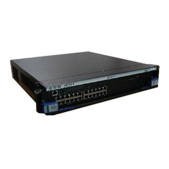
DFE-Platinum Module DFE-Platinum Module This section provides an overview of the 2G4082‐25 DFE module (Figure about features of the DFE‐Platinum modules and how to configure them, refer to the Enterasys Matrix DFE‐Diamond/Platinum Series Configuration Guide. 2G4082-25 Note: The DFE-Platinum 2G4082-25 module can be installed in the single-slot of the Matrix N1 chassis, or in any slot of the Matrix E7, Matrix N7, Matrix N5, or Matrix N3, but does not have FTM connectivity. -
Page 19: Dfe-Platinum 2G4082-25 Module
Figure 1-1 DFE-Platinum 2G4082-25 Module 1 OFFLINE/RESET switch 2 RJ45 COM (Console Port) 3 CPU LED 4 MGMT LED 5 GROUP SELECT button À Á Â Ã Ä Å È Æ Ç GROUP status LEDs GROUP selected LEDs NEM option slot Ports (1-24) 10/100/1000 Mbps, via 24 RJ45s Matrix DFE-Platinum Series Installation Guide 1-3 DFE-Platinum Module... -
Page 20: Network Expansion Module (Nem) Option
Network Expansion Module (NEM) Option Network Expansion Module (NEM) Option The 2G4082‐25 option slot provides access to an installed network expansion module. Refer to the Enterasys Networks web site for a current listing of the available NEMs. Specific installation instructions are shipped with each NEM. Connectivity Depending on how the 2G4082‐25 is configured, it can support up to: • 24, 10BASE‐T/100BASE‐TX/1000BASE‐T switched ports connected through 24, fixed RJ45 front panel connectors, or • 24, 10BASE‐T/100BASE‐TX/1000BASE‐T switched ports plus an optional network expansion module. Management Management of the module can be either in‐band or out‐of‐band. In‐band remote management is possible using Telnet, Enterasys Networks’ NetSight application. Out‐of‐band management is provided through the RJ45 COM (Communication) port on the front panel using a VT100 terminal or a VT100 terminal emulator. Switch Configuration Using WebView Enterasys Networks’ HTTP‐based Web management application (WebView) is an intuitive web tool for simple management tasks. Switch Configuration Using CLI Commands The CLI commands enable you to perform more complete switch configuration management tasks. For CLI command set information and how to configure the module, refer to the Enterasys Matrix DFE‐Diamond/Platinum Series Configuration Guide. -
Page 21: Secure Networks Policy Support
Secure Networks Policy Support A fundamental concept that is key to the implementation of the Enterasys Secure Networks methodology is policy‐enabled networking. This approach provides users of the network with the resources they need ‐ in a secure fashion – while at the same time denying access to applications or protocols that are deemed inappropriate based on the user’s function within the organization. By adopting such a “user‐personalized” model, it is possible for business policies to be the guidelines in establishing the technology architecture of the enterprise. Two major objectives are achieved in this way: IT services are matched appropriately with individual users; and the network itself becomes an active participant in the organization’s security strategy. The Secure Networks architecture consists of three tiers: • Classification rules make up the first or bottom tier. The rules apply to devices in the Secure Networks environment, such as switches and routers. The rules are designed to be implemented at or near the user’s point of entry to the network. Rules may be written based on criteria defined in the Layer 2, Layer 3 or Layer 4 information of the data frame. • The middle tier is Services, which are collections of individual classification rules, grouped logically to either permit or deny access to protocols or applications based on the user’s role within the organization. Priority and bandwidth rate limiting may also be defined in services. • Roles, or behavioral profiles, make up the top tier. The roles assign services to various business functions or departments, such as executive, sales, and engineering. To enhance security and deliver a true policy‐based infrastructure, the Enterasys Secure Networks methodology can take advantage of authentication methods, such as 802.1X, using EAP‐TLS, EAP‐ TTLS, or PEAP, as well as other types of authentication. Authorization information, attached to the authentication response, determines the application of policy. Authorization information is communicated via the policy name in a RADIUS Filter‐ID attribute. An administrator can also define a role to be implemented in the absence of an authentication framework. Refer to the release notes shipped with the module for details. Standards Compatibility The DFE modules are fully compliant with the IEEE 802.3‐2002, 802.3ae‐2002, 802.1D‐1998, and 802.1Q‐1998 standards. The DFE module provides IEEE 802.1D‐1998 Spanning Tree Algorithm (STA) support to enhance the overall reliability of the network and protect against “loop” conditions. LANVIEW Diagnostic LEDs LANVIEW diagnostic LEDs serve as an important troubleshooting aid by providing an easy way ... - Page 22 LANVIEW Diagnostic LEDs 1-6 Introduction...
-
Page 23: Chapter 2: Network Requirements
100BASE-TX Network 1000BASE-T Network 1000BASE-SX/LX/ELX Network Note: The Matrix DFE-Diamond/Platinum Series Configuration Guide and the Cabling Guide referred to in the following sections can be found on the Enterasys Networks World Wide Web site: http://www. Refer to Link Aggregation Link Aggregation is a method of grouping multiple physical ports on a network device into one ... -
Page 24: 10Base-T Network
10BASE-T Network 10BASE-T Network When connecting a 10BASE‐T segment to any of the fixed front panel ports of the 2G4082‐25, ensure that the network meets the Ethernet network requirements of the IEEE 802.3‐2002 standard for 10BASE‐T. Refer to the Cabling Guide for details. Note: If a port is to operate at 100 Mbps, Category 5 cabling must be used. Category 3 cabling does not meet 100 Mbps specifications. For 10 Mbps operation only, Category 3 or Category 5 cabling can be used. -
Page 25: Chapter 3: Installation
Electrical Hazard: Only qualified personnel should perform installation procedures. Riesgo Electrico: Solamente personal calificado debe realizar procedimientos de instalacion. Elektrischer Gefahrenhinweis: Installationen sollten nur durch ausgebildetes und qualifiziertes Personal vorgenommen werden. Read the Release Notes shipped with the DFE-Platinum module to check for any exceptions to the supported features and operation documented in this guide. -
Page 26: Unpacking The Dfe-Platinum Module
Table 3-1 Contents of DFE-Platinum Module Carton Item DFE-Platinum Module (2G4082-25 This Installation Guide Customer Release Notes Remove the tape seal on the non‐conductive bag to remove the DFE module. Perform a visual inspection of the DFE‐Platinum module for any signs of physical damage. Contact Enterasys Networks if there are any signs of damage. Refer to “Getting Help” on page xiii for details. Installing Optional Network Expansion Modules Note: Install any optional equipment before installing the 2G4082-25 into a chassis A Phillips screwdriver is needed to install an optional NEM into the 2G4082‐25. At the time of this printing, only the 7G‐6MGBIC‐A NEM is available for the 2G4082‐25. Refer to your release notes for the latest available Ethernet interface modules. The 7G‐6MGBIC‐A provides ... -
Page 27: Preparation
Preparation Remove the blank panel covering the module slot in which the module will be installed. All other slots must remain covered to ensure proper airflow for cooling. (Save the blank plate in the event you need to remove the module.) Remove the module from the shipping box. (Save the box and packing materials in the event the module needs to be reshipped.) Locate the antistatic wrist strap shipped with the chassis. Attach the antistatic wrist strap to your wrist and plug the cable from the antistatic wrist strap into the ESD grounding receptacle at the upper right corner of the chassis. Remove the module from the plastic bag. (Save the bag in the event the module must be reshipped.) Observe all precautions to prevent damage from Electrostatic Discharge (ESD). Examine the module for damage. If any damage exists, DO NOT install the module. Immediately contact Enterasys Networks. Refer to “Getting Help” on page xiii. Installation Note: The DFE-Platinum 2G4082-25 module can be installed in the single-slot of the Matrix N1 chassis, or in any slot of the Matrix E7, Matrix N7, Matrix N5, or Matrix N3, but does not have FTM connectivity. -
Page 28: Installing Module Into Matrix E7 Or Matrix N7 Chassis (E7 Shown)
Installing Module into Matrix E7 or N7 Chassis Caution: In step 4, do not force the locking levers to the point that they touch the face of the front panel. Forcing the locking levers to this point could damage the module and chassis. Precaución: En el paso 4, tenga cuidado de no llevar las palancas de cierre a un punto en donde estén en contacto con el panel frontal. -
Page 29: Installing Module Into Matrix N1, N3, Or N5 Chassis
Installing Module into Matrix N1, N3, or N5 Chassis Caution: Failure to observe static safety precautions could cause damage to the DFE module. Follow static safety handling rules and wear the antistatic wrist strap. Do not cut the non-conductive bag to remove the module. Sharp objects contacting the board or components can cause damage. -
Page 30: Connecting To The Network
Connecting to the Network Figure 3-2 Installing Module into N3, N1, or N5 Chassis (N3 shown) Æ 1 Card guides 2 Slot 1 (Top slot is slot 3.) 3 Module card 4 Metal back panel Connecting to the Network This section provides the procedures for connecting unshielded twisted pair (UTP) segments from the network or other devices to the 2G4082‐25 (“Connecting UTP Cables” on page 3‐6). ... -
Page 31: Connecting A Twisted Pair Segment To The Dfe-Platinum Module
Figure 3‐3 shows connecting a twisted pair segment to the 2G4082‐25 module. It is assumed that the chassis power is turned on to provide power to the module. Refer to Figure follows: Ensure that the device connected to the other end of the segment is powered ON. Connect the twisted pair segment to the module by inserting the RJ45 connector on the twisted pair segment into the appropriate RJ45 port connector. Figure 3-3 Connecting a Twisted Pair Segment to the DFE-Platinum Module À 1 RJ45 connector 2 RJ45 port connector (port 1) Verify that a link exists by checking that the port RX (Receive) LED is ON (flashing amber, blinking green, or solid green). If the RX LED is OFF and the TX (Transmit) LED is not blinking amber, perform the following steps until it is on: To view the receive and transmit activity on a group of segments, press the GROUP SELECT button (see Figure time the GROUP SELECT button is pressed, the GROUP LED lights up in sequence, indicating which Group is selected. The receive and transmit activity for that group of segments is then indicated by the RX and TX LEDs for each segment. b. Verify that the cabling being used is Category 5 UTP with an impedance between 85 and 111 ohms. For the port to operate at 100 or 1000 Mbps, Category 5 cabling must be used and installed properly. -
Page 32: Four-Wire Crossover Cable Rj45 Pinouts, Connections Between Hub Devices
Connecting to the Network Figure 3-4 Four-Wire Crossover Cable RJ45 Pinouts, Connections Between Hub Devices 1 RJ45 device port 2 Other device port Figure 3-5 Four-Wire Straight-Through Cable RJ45 Pinouts, Connections Between Switches and End User Devices 1 RJ45 device port 2 Other device port 3-8 Installation À... -
Page 33: Eight-Wire Straight-Through Cable Rj45 Pinouts, Connections
Figure 3-6 Eight-Wire Crossover Cable RJ45 Pinouts, Connections Between Hub Devices À 1 RJ45 device port 2 Other device port Figure 3-7 Eight-Wire Straight-Through Cable RJ45 Pinouts, Connections Between Switches and End-User Devices À 1 RJ45 device port 2 Other device port Ensure that the twisted pair connection meets the dB loss and cable specifications outlined ... -
Page 34: Connecting To Com Port For Local Management
Connecting to COM Port for Local Management Connecting to COM Port for Local Management This section describes how to install a UTP straight‐through cable with RJ45 connectors and optional adapters to connect a PC, a VT series terminal, or a modem to an Enterasys Networks module to access Local Management. This section also provides the pinout assignments of the adapters. What Is Needed The following is a list of the user‐supplied parts that may be needed depending on the connection: • RJ45‐to‐DB9 female adapter • UTP straight‐through cable with RJ45 connectors • RJ45‐to‐DB25 female adapter • RJ45‐to‐DB25 male adapter With a UTP straight‐through cable with RJ45 connectors and RJ45‐to‐DB9 adapter, you can connect products equipped with an RJ45 COM port to an IBM or compatible PC running a VT series emulation software package. With a UTP straight‐through cable and RJ45‐to‐DB25 female adapter, you can connect products equipped with an RJ45 COM port to a VT series terminal or VT type terminals running emulation programs for the VT series. With a UTP straight‐through cable and an RJ45‐to‐DB25 male adapter, you can connect products equipped with an RJ45 COM port to a Hayes compatible modem that supports 9600 baud. -
Page 35: Connecting To A Vt Series Terminal
Figure 3-8 Connecting an IBM PC or Compatible 1 UTP straight-through cable with RJ45 connectors 2 RJ45 COM port Connecting to a VT Series Terminal To connect a VT Series terminal to an Enterasys Networks DFE‐Platinum module COM port (Figure 3‐9), use a UTP straight‐through cable with RJ45 connectors and an RJ45‐to‐DB25 female adapter, and proceed as follows: Connect the RJ45 connector at one end of the UTP straight‐through cable to the COM port on the Enterasys Networks module. Plug the RJ45 connector at the other end of the UTP straight‐through cable into the RJ45‐to‐ DB25 female adapter. Connect the RJ45‐to‐DB25 adapter to the port labeled COMM on the VT terminal. Turn on the terminal and access the Setup Directory. Set the following parameters on your terminal: Parameter Mode... -
Page 36: Connecting To A Modem
Connecting to COM Port for Local Management Figure 3-9 Connecting a VT Series Terminal 1 UTP straight-through cable with RJ45 connectors 2 RJ45 COM port Connecting to a Modem To connect a modem to an Enterasys use a UTP straight‐through cable with RJ45 connectors and an RJ45‐to‐DB25 male adapter, and proceed as follows: Connect the RJ45 connector at one end of the UTP straight‐through cable to the COM port of the DFE‐Platinum module. Plug the RJ45 connector at the other end of the UTP straight‐through cable into the RJ45‐to‐ DB25 modem adapter. Connect the RJ45‐to‐DB25 adapter to the communications port on the modem. Turn on the modem. With a PC connected to a remote modem, you can configure the switch remotely. To accomplish this, you must configure your PC VT emulation package with the following parameters. -
Page 37: Adapter Wiring And Signal Assignments
Pin Out Descriptions Figure 3-10 Connecting to a Modem Å 1 UTP straight-through cable with RJ45 connectors 2 RJ45 COM port 3 RJ45-to-DB25 modem adapter Adapter Wiring and Signal Assignments RJ45 Ä Ã COM Port Adapter Wiring and Signal Diagram Conductor Blue Green... - Page 38 Connecting to COM Port for Local Management RJ45 RJ45 3-14 Installation VT Series Port Adapter Wiring and Signal Diagram DB25 Conductor Blue Yellow Green Orange Modem Port Adapter Wiring and Signal Diagram DB25 Conductor Blue Orange Green Yellow Gray Pin Out Descriptions Signal Transmit (TX) Receive (RX)
-
Page 39: Completing The Installation Of A New System
Pin Out Descriptions Completing the Installation of a New System Note: The DFE-Platinum 2G4082-25 module can be installed in the single-slot of the Matrix N1 chassis, or in any slot of the Matrix E7, Matrix N7, Matrix N5, or Matrix N3, but does not have FTM connectivity. -
Page 40: Logging In With An Administratively-Configured User Account
Command Line Interface Enterasys Networks, Inc. 50 Minuteman Rd. Andover, MA 01810-1008 U.S.A. Phone: E-mail: support@enterasys.com WWW: (c) Copyright Enterasys Networks, Inc. 2003 Chassis Serial Number: Chassis Firmware Revision: xx.xx.xx Matrix N7(su)-> Logging in with an Administratively-Configured User Account If the device’s default user account settings have been changed, proceed as follows: At the login prompt, enter your administratively‐assigned user name and press Enter. -
Page 41: Chapter 4: Troubleshooting
This chapter provides information concerning the following: For information about... Using LANVIEW Troubleshooting Checklist Overview of DFE-Platinum Module Shutdown Procedure Recommended Shutdown Procedure Last Resort Shutdown Procedure Unless otherwise noted, the following information applies to all DFE modules. Using LANVIEW The modules use a built‐in visual diagnostic and status monitoring system called LANVIEW. The LANVIEW LEDs (Figure network problems. About the Management (MGMT) LED The MGMT LED (shown in Figure Module to control the management functions for all DFE‐Platinum modules in the chassis. The Management Module handles all IP requests to the chassis IP address, such as PING, Telnet, SNMP, and HTTP. The Management Module also handles the CLI configuration sessions by means of the console port. So, when you plug into a DFE‐Platinum module COM port to configure a module in the chassis, it is handled by the Management Module regardless of the DFE‐Platinum module COM port that you use. Viewing the Receive and Transmit Activity On the 2G4082‐25, you can view the receive and transmit activity on the RX and TX LEDs. ... -
Page 42: Lanview Leds
Using LANVIEW Figure 4-1 LANVIEW LEDs 1 MGMT LED Table 4‐1 describes the LED indications and provides recommended actions as appropriate. The terms used in • Flashing indicates an LED is flashing randomly. • Blinking indicates an LED is flashing at a steady rate (approximately 50% on, 50% off). • Solid indicates a steady LED light. No pulsing. •... - Page 43 None. Contact Enterasys Networks for technical support. If it is known that the port should be active and is not, contact Enterasys Networks for technical support. None. None, unless there is a high rate of activity. In this case, check for network configuration problems or a defective device.
-
Page 44: Troubleshooting Checklist
No link to device. Verify that all network connections between the network management station and the module are valid and operating. If the problem continues, contact Enterasys Networks for technical support. Loop condition detected. Verify that Spanning Tree is enabled. Refer to the... -
Page 45: Overview Of Dfe-Platinum Module Shutdown Procedure
Configuration Guide for the instructions to configure either cycling power or the device. pressing the OFFLINE/ If the problem continues, contact Enterasys Networks RESET switch, causing the for technical support. user-entered parameters to reset to factory default settings. -
Page 46: Recommended Shutdown Procedure
Overview of DFE-Platinum Module Shutdown Procedure Recommended Shutdown Procedure Caution: Do not remove a DFE module from an operating chassis system before reading the following information and instructions. Precaución: Antes de retirar los módulos DFE del chasis en funcionamiento, lea las siguientes instrucciones y la información suministrada. -
Page 47: Appendix A: Specifications
This appendix provides information about the following: For information about... DFE-Platinum Module Specifications COM Port Pinout Assignments Regulatory Compliance Enterasys Networks reserves the right to change the specifications at any time without notice. DFE-Platinum Module Specifications Table A‐1 provides the I/O ports, processors and memory, physical, and environmental module specifications for the 2G4082‐25. Table A-1 Specifications for 2G4082-25 Item Ports Ports 1 through 24 Network Expansion Module option slot Processors/Memory Processor Dynamic Random Access Memory... -
Page 48: Com Port Pinout Assignments
COM Port Pinout Assignments Table A-1 Specifications for 2G4082-25 (continued) Item Environmental Operating Temperature Storage Temperature Operating Relative Humidity COM Port Pinout Assignments The COM port is a serial communications port for local access to Local Management. Refer to Table A‐2 for the COM port pin assignments. Table A-2 COM Port Pin Assignments Signal Name Transmit Data (XMT) Clear to Send (CTS) Data Set Ready (DSR) Receive Data (RCV) Signal Ground (GND) -
Page 49: Appendix B: Mode Switch Bank Settings And Optional Installations
This appendix covers the following items: For information about... Required Tools Setting the Mode Switches Memory Locations and Replacement Procedures Required Tools Use the following tools to perform the procedures provided in this appendix: • Antistatic wrist strap • Phillips screwdriver Caution: An antistatic wrist strap is required to perform the following procedures to minimize ESD damage to the devices involved. Precaución: Para minimizar los efectos de las descargas de electricidad estática, deberá... -
Page 50: Memory Locations And Replacement Procedures
Memory Locations and Replacement Procedures • Switch 8 – Clear Admin Password. Changing the position of this switch clears the admin password, and restores the factory default password on the next power‐up of the module. Once the module resets, you can either use the factory default settings or reenter your own password. Note: Do not change the position of Switch 8 unless it is necessary to reset the admin password to its factory default setting. Figure B-1 Mode Switch Location on 2G4082-25 1 Mode switch bank Memory Locations and Replacement Procedures In the event that the Dual In‐Line Memory Module (DIMM) or DRAM Single In‐line Memory ... -
Page 51: Location Of Memory Modules
Location of Memory Modules Figure B‐2 shows the locations of the DRAM SIMM and DIMM on the main board of the 2G4082‐25. Figure B-2 Memory Module Locations on the 2G4082-25 Flash DIMM Flash DIMM Replacement Procedure Caution: Observe all Electrostatic Discharge (ESD) precautions when handling sensitive electronic equipment. Precaución: Al trabajar con equipos electrónicos sensibles, tome todas las precauciones de seguridad para evitar descargas de electricidad estática. -
Page 52: Nem Removal And Dimm Connector Location
Memory Locations and Replacement Procedures Figure B-3 NEM Removal and DIMM Connector Location 1 NEM (optional) 2 Main PC board 3 Screws (3) Refer to Figure DIMM enough to release it from the connector fingers. Figure B-4 Removing the Existing DIMM 1 Connector arms Rotate the DIMM upwards, then remove it from the connector fingers. B-4 Mode Switch Bank Settings and Optional Installations Ä... -
Page 53: Installing The Dimm
Installing the DIMM Caution: Observe all Electrostatic Discharge (ESD) precautions when handling sensitive electronic equipment. Precaución: Al trabajar con equipos electrónicos sensibles, tome todas las precauciones de seguridad para evitar descargas de electricidad estática. To install a DIMM, refer to Figure Insert the DIMM down between the connector fingers. Pivot the DIMM downward so the tabs on the connector arms align with the two DIMM alignment notches. With the two connector arms spread outward, push the DIMM down between the connector arms. Then release the two connector arms to lock the DIMM into place. Figure B-5 Installing the DIMM 1 DIMM... -
Page 54: Dram Simm Replacement Procedure
Memory Locations and Replacement Procedures DRAM SIMM Replacement Procedure Caution: Observe all Electrostatic Discharge (ESD) precautions when handling sensitive electronic equipment. Precaución: Al trabajar con equipos electrónicos sensibles, tome todas las precauciones de seguridad para evitar descargas de electricidad estática. Removing the DRAM SIMM To remove the existing DRAM SIMM, proceed as follows: Locate the DRAM SIMM connector on the main PC board. Refer back to Figure... -
Page 55: Installing The Dram Simm
Figure B-7 Installing the DRAM SIMM Ã À 1 DRAM SIMM Connector arms 2 DRAM SIMM Memory Locations and Replacement Procedures Á Ã À Â 3 Connector contacts 4 DRAM SIMM alignment notches (2) Matrix DFE-Platinum Series Hardware Installation Guide B-7... - Page 56 Memory Locations and Replacement Procedures B-8 Mode Switch Bank Settings and Optional Installations...
- Page 57 Numerics 1000BASE-SX/LX/ELX network connections requirements for 1000BASE-T network connections requirements for 100BASE-TX requirements 10BASE-T connection requirements 2G4082-25 introduction to Cable connections 2G4082-25 Cable specifications 1000BASE-SX/LX/ELX network 1000BASE-T network 100BASE-TX network 10BASE-T network CLI command introduction to COM port connections what is needed 3-10 Connecting to the network Console port...
- Page 58 Index-2...