
Related Manuals for Enterasys 6H302-48


Summary of Contents for Enterasys 6H302-48
- Page 1 6H302-48 and 6H303-48 Fast Ethernet User’s Guide RESET RESET 9033387-05...
- Page 3 Enterasys Networks reserves the right to make changes in specifications and other information contained in this document and its web site without prior notice. The reader should in all cases consult Enterasys Networks to determine whether any such changes have been made.
-
Page 4: Fcc Notice
FCC NOTICE This device complies with Part 15 of the FCC rules. Operation is subject to the following two conditions: (1) this device may not cause harmful interference, and (2) this device must accept any interference received, including interference that may cause undesired operation. - Page 5 BEFORE OPENING OR UTILIZING THE ENCLOSED PRODUCT, CAREFULLY READ THIS LICENSE AGREEMENT. This document is an agreement (“Agreement”) between You, the end user, and Enterasys Networks, Inc. (“Enterasys”) that sets forth your rights and obligations with respect to the Enterasys software program (“Program”) in the package.
- Page 6 UNITED STATES GOVERNMENT RESTRICTED RIGHTS. The enclosed Product (i) was developed solely at private expense; (ii) contains “restricted computer software” submitted with restricted rights in accordance with section 52.227-19 (a) through (d) of the Commercial Computer Software-Restricted Rights Clause and its successors, and (iii) in all respects is proprietary data belonging to Enterasys and/or its suppliers.
-
Page 7: Declaration Of Conformity
Manufacturer’s Address: European Representative Address: Conformance to Directive(s)/Product Standards: Equipment Type/Environment: Networking Equipment, for use in a Commercial Enterasys Networks, Inc. declares that the equipment packaged with this notice conforms to the above directives. 73/23/EEC 35 Industrial Way PO Box 5005 Rochester, NH 03866-5005 Enterasys Networks Ltd. -
Page 9: Table Of Contents
Remote Monitoring (RMON) ... 1-4 Broadcast Suppression ... 1-4 Port/VLAN Redirect Functions ... 1-4 Traffic Rate Limiting ... 1-5 Flow Control ... 1-5 1.10 GARP Switch Operation... 1-6 1.11 802.1 Port Priority ... 1-6 1.12 Distributed Chassis Management ... 1-6 1.13 Management ... - Page 10 COM Port Pinout Assignments ...A-3 Regulatory Compliance...A-3 Required Tools...B-1 Setting the Mode Switches...B-2 FLASH Upgrade...B-4 B.3.1 B.3.2 INDEX viii Contents Connecting UTP Cables to the 6H302-48... 3-7 Connecting UTP Cables to the 6H303-48... 3-9 Locating the FLASH Module ...B-4 Installing the FLASH Module ...B-5...
-
Page 11: Figures
6H302-48 and 6H303-48 Modules ... 1-2 Installing a Module into the Matrix E7 Chassis... 3-4 Installing a Module into the 6C105 Chassis ... 3-6 Connecting a Twisted Pair Segment to the 6H302-48 ... 3-8 Crossover Cable RJ45 Pinouts ... 3-9 Straight-Through Cable RJ45 Pinouts... 3-9 Connecting a Twisted Pair Segment to the 6H303-48 ... - Page 12 Tables Table Contents of Module Carton ...3-2 LANVIEW LEDs ...4-3 Troubleshooting Checklist...4-5 6H302-48 / 6H303-48 Specifications ... A-1 COM Port Pin Assignments ... A-3 Compliance Standards... A-3 Tables Page...
-
Page 13: About This Guide
PIC MIB. For firmware in the 5.x track, version 5.03.05 or higher must be used on 6H302-48 modules with a serial number starting with 3655. For the 4.x firmware track, 4.08.41 or higher must be used on 6H302-48 modules with a serial number starting with 3655. -
Page 14: Structure Of This Guide
The manuals listed above can be obtained from the World Wide Web in Adobe Acrobat Portable Document Format (PDF) at the following site: http://www.enterasys.com NOTE: All documentation for the Enterasys Networks SecureFast VLAN Manager software is contained on the VLAN Manager CD-ROM. About This Guide... -
Page 15: Document Conventions
DOCUMENT CONVENTIONS The guide uses the following conventions: Note symbol. Calls the reader’s attention to any item of information that may be of special importance. Tip symbol. Conveys helpful hints concerning procedures or actions. Caution symbol. Contains information essential to avoid damage to the equipment. Electrical Hazard Warning symbol. -
Page 16: Getting Help
Getting Help GETTING HELP For additional support related to the module or this document, contact Enterasys Networks using one of the following methods: World Wide Web http://www.enterasys.com/ Phone (603) 332-9400 Internet mail support@enterasys.com ftp://ftp.enterasys.com Login anonymous Password your email address To send comments or suggestions concerning this document, contact the Technical Writing Department via the following email address: TechWriting@enterasys.com... -
Page 17: Important Notice
PIC MIB. For firmware in the 5.x track, version 5.03.05 or higher must be used on 6H302-48 modules with a serial number starting with 3655. For the 4.x firmware track, 4.08.41 or higher must be used on 6H302-48 modules with a serial number starting with 3655. -
Page 18: H302-48 And 6H303-48 Modules
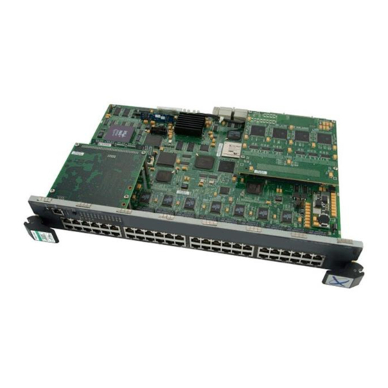
Figure 1-1 6H302-48 and 6H303-48 Modules RESET RESET Introduction... -
Page 19: Connectivity
CONNECTIVITY The module connects to Ethernet networks or workstations through the front panel connectors. The ports support Unshielded Twisted Pair (UTP) cables with an impedance between 85 and 111 ohms at lengths up to 100 meters. The ports are IEEE 802.3 10BASE-T and 100BASE-TX compliant. RUNTIME IP ADDRESS DISCOVERY This feature enables the module to automatically accept an IP address from a Boot Strap Protocol (BootP) server on the network without requiring a user to enter an IP address through Local... -
Page 20: Remote Monitoring (Rmon)
The module supports all nine Ethernet RMON groups. The Statistics, Alarms, Events and History groups are enabled on all ports by default. Enterasys Networks RMON Actions is a vendor-specific extension of RMON and provides the ability to set an “Action” on any SNMP MIB variable. The Action can be triggered by any RMON Event and/or Alarm. -
Page 21: Traffic Rate Limiting
VLAN classification of the frames received. Multiple VLANs can be directed to the same destination port. The VLAN redirect function is only supported when the module is operating as an 802.1Q switch. TRAFFIC RATE LIMITING The Traffic Rate Limiting feature enables the module to control traffic rates on a per-port, per-priority basis. -
Page 22: Garp Switch Operation
GARP attributes such as VLAN and multicast group membership. For more details on how GVRP and GMRP handle frames under GARP, and how to configure the switch ports to take advantage of this operation, refer to the Matrix E7 Series and SmartSwitch 6000 Series Local Management User’s Guide. -
Page 23: Management
The SmartSwitch 6000 chassis can be viewed as a single entity with a single IP address. Its systems management functions are distributed to all modules, including the 6H302-48 or 6H303-48. The chassis can be managed using a single IP address, or the modules can be managed separately by individual IP addresses. -
Page 24: Standards Compatibility
Standards Compatibility 1.15 STANDARDS COMPATIBILITY The 6H302-48 and 6H303-48 modules are fully compliant with the IEEE 802.3, 802.3u, 802.3x, 802.1D, and 802.1Q standards. The modules provide IEEE 802.1D Spanning Tree Algorithm (STA) support to enhance the overall reliability of the network and protect against “loop”... -
Page 25: Smarttrunk Feature
Failure to do so will produce poor network performance. NOTE: The appropriate Local Management User’s Guide and Cabling Guide referred to in the following sections can be found on the Enterasys Networks World Wide Web site: http://www.enterasys.com/ SMARTTRUNK FEATURE... -
Page 26: 100Base-Tx Network
100BASE-TX Network 100BASE-TX NETWORK The fixed front panel ports of the module provide a connection that supports Category 5 UTP cabling. The device at the other end of the twisted pair segment must meet IEEE 802.3u 100BASE-TX Fast Ethernet network requirements for the devices to operate at 100 Mbps. Refer to the Cabling Guide for details. - Page 27 NOTE: Read the Release Notes shipped with the module to check for any exceptions to the supported features and operation documented in this guide. This chapter provides the instructions to install the 6H302-48 or 6H303-48 module. A Phillips screwdriver is required to install options into the module. Follow the order of the sections listed below to correctly install the module.
-
Page 28: Unpacking The Module
2. Verify the contents of the carton as listed in Table 3-1 Contents of Module Carton Item One module, either the 6H302-48 or the 6H303-48 Antistatic Wrist Strap Manual Accessory Kit 3. Remove the tape seal on the non-conductive bag to remove the module. - Page 29 NOTE: The Matrix E7 (third generation modules) can provide backplane connectivity for the 6x1xx and 6x2xx series (first and second generation modules) in the Matrix E7 chassis. First and second generation boards installed in slots one through five in the Matrix E7 chassis cannot communicate with slots six and seven unless a third generation board (6x3xx) is installed in one of the first five slots.
-
Page 30: Installing A Module Into The Matrix E7 Chassis
Installing the Module into the Matrix E7 Chassis Figure 3-1 Installing a Module into the Matrix E7 Chassis SERIES RESET Installation... -
Page 31: Installing The Module Into The 6C105 Chassis
Certain restrictions may apply when installing the module into the 6C105 chassis. Refer to the Release Notes for any updated information concerning installing the 6H302-48 or 6H303-48 modules into the 6C105 chassis. Otherwise, the installation procedure from followed, with the exception of the fact that the 6C105 chassis has only 5 slots as opposed to the 7 slots in the Matrix E7. -
Page 32: Installing A Module Into The 6C105 Chassis
Installing the Module into the 6C105 Chassis Figure 3-2 Installing a Module into the 6C105 Chassis RESET Installation... -
Page 33: Connecting To The Network
3.5.1 Connecting UTP Cables to the 6H302-48 The fixed front panel ports of the 6H302-48 are 10/100 RJ45 ports with internal crossovers. When connecting a workstation to these ports, use a straight-through cable. When connecting networking devices to these ports, such as a bridge, repeater, or router, use a crossover cable. -
Page 34: Connecting A Twisted Pair Segment To The 6H302-48
Connecting to the Network Figure 3-3 Connecting a Twisted Pair Segment to the 6H302-48 3. Verify that a link exists by checking that the port RX (Receive) LED is ON (flashing amber, blinking green, or solid green). If the RX LED is OFF and the TX (Transmit) LED is not blinking amber, perform the following steps until it is on: a. -
Page 35: Connecting Utp Cables To The 6H303-48
Ensure that the twisted pair connection meets the dB loss and cable specifications outlined in the Cabling Guide. Refer to document. If a link is not established, contact Enterasys Networks. Refer to Guide for details. 4. Repeat steps 1 through 3 above, until all connections have been made. -
Page 36: Connecting A Twisted Pair Segment To The 6H303-48
Connecting to the Network To connect a UTP segment to the 6H303-48, proceed as follows: 1. Ensure that the device connected to the other end of the segment is powered ON. 2. If using an RJ21 straight connector, plug it into the appropriate RJ21 port as shown in Figure 3-6. -
Page 37: Completing The Installation
Verify that the RJ21 connectors on the twisted pair segment have the proper pinouts and check the cable for continuity. c. Check that the twisted pair connection meets the specifications in the Cabling Guide. If a link is not established, contact Enterasys Networks. Refer to Guide for details. -
Page 39: Lanview Leds
This chapter provides information concerning the following: • Using LANVIEW (Section • Troubleshooting Checklist • Using the RESET Button USING LANVIEW The modules use a built-in visual diagnostic and status monitoring system called LANVIEW. The LANVIEW LEDs (Figure 4-1) allow quick observation of the network status to aid in diagnosing network problems. -
Page 40: Lanview Leds (Both Modules)
Using LANVIEW Figure 4-1 LANVIEW LEDs (both modules) Table 4-1 describes the LED indications and provides recommended actions as appropriate. NOTE: The terms flashing, blinking, and solid used in Flashing indicates an LED is flashing randomly. Blinking indicates an LED is flashing at a steady rate (approximately 50% on, 50% off). Solid indicates a steady LED light. - Page 41 Flashing. Link, port enabled, activity. Solid. Diagnostic failure. Recommended Action Ensure chassis has adequate power. Contact Enterasys Networks for technical support. If the LED remains red for several minutes, contact Enterasys Networks for technical support. Contact Enterasys Networks for technical support.
- Page 42 Solid. Diagnostic failure. Troubleshooting Recommended Action 1. Ensure that the STA is enabled and that there is a valid link. 2. Contact Enterasys Networks for technical support. None. 1. Ensure that the port is not disabled. 2. Contact Enterasys Networks for technical support.
-
Page 43: Troubleshooting Checklist
Community Names Table setup. 2. If the Community Names have been forgotten, refer to Section B.2 instructions on how to set the mode switch to reset the Community Names to their default values. 3, and that the host Section B.2... - Page 44 2. If the problem continues, contact Enterasys Networks for technical support. 1. Verify that Spanning Tree is enabled. Refer to the appropriate Local Management User’s Guide for the instructions to set the type of STA.
-
Page 45: Using The Reset Button
USING THE RESET BUTTON The RESET button shown in CAUTION: Pressing the RESET button resets the device, and all current switching being performed by the module is halted. A network downtime of up to two minutes will result from this action for any devices connected to the module. Figure 4-2 RESET Button (both modules) To reset the module processor, press and release the RESET button. -
Page 47: A-1 6H302-48 / 6H303-48 Specifications
This appendix provides operating specifications for the 6H302-48 and 6H303-48 modules. Enterasys Networks reserves the right to change the specifications at any time without notice. If not specified by module name, the statistics are the same for both modules. 6H302-48 / 6H303-48 SPECIFICATIONS... -
Page 48: 6H302-48 / 6H303-48 Specifications
6H302-48 / 6H303-48 Specifications Table A-1 6H302-48 / 6H303-48 Specifications (Continued) Item Environmental Requirements Operating Temperature: Storage Temperature: Operating Relative Humidity: Input/Output Ports 6H302-48: Ports 1 through 48: 6H303-48: Ports 1 through 48: Specifications Specification 5°C to 40°C (41°F to 104°F) -30°C to 73°C (-22°F to 164°F) -
Page 49: Com Port Pinout Assignments
Signal Ground (GND) Data Terminal Ready (DTR) Request to Send (RTS) Clear to Send (CTS) REGULATORY COMPLIANCE The 6H302-48 and 6H303-48 modules meet the following safety and electromagnetic compatibility (EMC) requirements: Table A-3 Compliance Standards Regulatory Compliance Safety Electromagnetic Compatibility (EMC) -
Page 51: Required Tools
Mode Switch Bank Settings and Options This appendix covers the following items: • Required tools (Section • Locations, functions, and settings for the mode switches • Upgrading the FLASH (Section REQUIRED TOOLS Use the following tools to perform the procedures provided in this appendix: •... -
Page 52: Setting The Mode Switches
These switches are set at the factory and rarely need to be changed. Switch definitions and positions are as follows: • Switches 1 through 4 – For Enterasys Networks use only. • Switch 5 – COM Port Autobaud. The default (OFF) position enables Autobaud sensing on the COM port for Local Management sessions. - Page 53 (TFTP) server containing the module image file. When the position of Switch 6 is changed and the power is cycled to the module, the device requests the image file location from the BootP server and uses TFTP to download the image from the TFTP server.
-
Page 54: Flash Upgrade
FLASH Upgrade FLASH UPGRADE FLASH upgrade is available for the switch to expand from 8 to 16 MB. This section explains how to locate and add/replace the FLASH module. For details on getting help, refer to About This Guide. B.3.1... -
Page 55: Installing The Flash Module
2. Pivot the FLASH module downward so the connector clips align with the two side notches of the FLASH module and the connector clips lock the FLASH module into place. Figure B-3 Installing the FLASH Figure B-3 and proceed as follows: Figure B-3, insert the FLASH module down Mode Switch Bank Settings and Options FLASH Upgrade... -
Page 57: Index
100BASE-TX requirements 10BASE-T connection 3-7, requirements 802.1p Port Priority introduction to Auto-Negotiation Broadcast Suppression introduction to Cable connections 6H302-48 6H303-48 Cable specifications 100BASE-TX network 10BASE-T network COM port pin assignments Connecting to the network Connectivity introduction to Distributed Chassis Management... - Page 58 Management use of Mode Switch setting Module features Module Installation Pinouts crossover straight-through Port redirect function introduction to Receive LEDs viewing of Redirect functions port and VLAN introduction to Regulatory Compliance Related manuals Remote Monitoring (RMON) introduction to RESET button...