Advertisement
Advertisement
Table of Contents

Summary of Contents for Hussmann Ingersoll Rand
- Page 1 INGERSOLL RAND Impact™ SEMI HERMETIC RECIPROCATING COMPRESSOR CATALOG HSM 52975-17-BD March 2007...
-
Page 3: Table Of Contents
Impact SEMI HERMETIC RECIPROCATING COMPRESSOR CATALOG INTRODUCTION This catalog is published by Hussmann Corporation to provide information required to select and service Ingersoll Rand Impact semi hermetic compressors. There are several major category tabs to enable quick access to required information. - Page 4 5. Electrical Data a. Electrical Description i. Rated Load Current ii. Component Sizing iii. Marking on Compressor Nameplate b. Tables – By Voltage, Application Range, and Refrigerant i. LRA ii. MCC iii. RLA iv. Circuit Breaker Size v. Contactor Size vi.
- Page 5 8. Lubrication a. Polyolester Lubricants i. IR POE32 b. Mineral Oils i. IR MO32 9. Aftermarket a. Model Number Nomenclature b. Compressor Part Numbers c. Distribution Network Map d. Contact Information List e. Cross Reference for Replacement Compressors i. Copeland ii.
- Page 7 Ingersoll Rand Impact Semi-hermetic Reciprocating Compressors Leading the way in Technology and Performance Low Pressure Drop Large Electrical Unloaders Service Valves Terminal Box Cast in Muffler Heads Electronic Motor Protection Chrome Plated Rings Dual Voltage, High Efficiency Motors Teflon Impregnated...
-
Page 8: Features And Benefits
Ingersoll Rand Impact Semi-hermetic Reciprocating Compressors Features and Benefits Small physical size and weight for comparable displacement and capacity Universal o One compressor version for all temperature ranges using R404A, R507, and R22 Smooth and Quiet Operation can be Attributed to:... - Page 9 Teflon Impregnated Bearings o Bearing composition is metal and PTFE (Teflon) o Allows for safe operation during marginal lubrication periods Eccentric Rods o Aluminum alloy o High quality and low tolerances can be maintained due to one-piece construction o Low bearing loading & high velocities, increase the running capability of bearings under boundary lubrication conditions Crankshaft o High quality cast iron...
- Page 10 Piston Rings o 4 & 6 cylinder models have two rings, a chrome plated compression ring and an oil ring o Chrome plated rings provide excellent running durability under boundary lubrication conditions o Piston rings are sealed by gas pressure balancing the ring tension to the proper value o Provides excellent sealing under various pressure and speed conditions Cylinder Design...
- Page 11 INGERSOLL RAND Impact SEMI HERMETIC RECIPROCATING COMPRESSOR Model Number Nomenclature IR 4 C 0000 S B Voltage B – 208-230/460/3/60 K – 208/230/3/60 M – 460/3/60 P – 575/3/60 R – 208/230/1 /60 Oil System S – Enhanced Centrifugal P – Pump T –...
-
Page 12: Model Number Description
INGERSOLL RAND Impact SEMI HERMETIC RECIPROCATING COMPRESSOR Nominal Horsepower Rating Table Compressor Nominal Model Number Horsepower IR2C0173 IR2C0222 0.75 IR2C0278 IR2C0323 1.25 IR2C0407 IR2C0484 IR2C0572 IR2C0692 IR4C0770 IR4C0969 IR4C1145 IR4C1385 IR4C1480 IR4C1761 IR4C2067 IR4C2397 IR4B2707 IR4B3139 IR4B3604 IR6B4060 IR6B4709 IR6B5406... - Page 13 IR2C0173S Conditions R-404A & R-507A 65 °F Return Gas No Liquid Sub Cooling Ingersoll-Rand "Impact" Compressor 460/3/60Hz Capacity [Btu/hr] Evaporating Temperature °F 2178 2705 3285 3924 4649 5458 6349 7331 8409 9591 10887 12303 13852 17386 1798 2284 2818 3405 4070 4811 5627...
- Page 14 IR2C0173S Conditions R-404A & R-507A Ingersoll-Rand "Impact" Compressor 65 °F Return Gas 460/3/60 Hz No Liquid Sub Cooling Capacity 20000 18000 16000 70 °F 14000 80 °F 12000 90 °F 10000 100 °F 8000 105 °F 6000 110 °F 4000 120 °F 2000 Evaporating Temperature °F...
- Page 15 IR2C0222S Conditions R-404A & R-507A 65 °F Return Gas No Liquid Sub Cooling Ingersoll-Rand "Impact" Compressor 460/3/60Hz Capacity [Btu/hr] Evaporating Temperature °F 3235 3907 4649 5465 6394 7430 8574 9833 11216 12734 14396 16215 18202 22739 2776 3400 4086 4842 5699 6656 7711...
- Page 16 IR2C0222S Conditions R-404A & R-507A Ingersoll-Rand "Impact" Compressor 65 °F Return Gas 460/3/60 Hz No Liquid Sub Cooling Capacity 30000 25000 70 °F 80 °F 20000 90 °F 15000 100 °F 105 °F 10000 110 °F 120 °F 5000 Evaporating Temperature °F Current @ 460 V 3 ph 60 Hz 70 °F 80 °F...
- Page 17 IR2C0278S Conditions R-404A & R-507A 65 °F Return Gas No Liquid Sub Cooling Ingersoll-Rand "Impact" Compressor 460/3/60Hz Capacity [Btu/hr] Evaporating Temperature °F 4385 5216 6134 7146 8302 9592 11018 12587 14313 16207 18282 20553 23035 28705 3784 4563 5423 6368 7444 8644 9968...
- Page 18 IR2C0278S Conditions R-404A & R-507A Ingersoll-Rand "Impact" Compressor 65 °F Return Gas 460/3/60 Hz No Liquid Sub Cooling Capacity 35000 30000 70 °F 25000 80 °F 90 °F 20000 100 °F 15000 105 °F 10000 110 °F 120 °F 5000 Evaporating Temperature °F Current @ 460 V 3 ph 60 Hz 70 °F...
- Page 19 IR2C0323S Conditions R-404A & R-507A 65 °F Return Gas No Liquid Sub Cooling Ingersoll-Rand "Impact" Compressor 460/3/60Hz Capacity [Btu/hr] Evaporating Temperature °F 5094 6056 7117 8283 9614 11098 12735 14536 16514 18684 21059 23658 26496 32975 4480 5371 6352 7431 8659 10029 11539...
- Page 20 IR2C0323S Conditions R-404A & R-507A Ingersoll-Rand "Impact" Compressor 65 °F Return Gas 460/3/60 Hz No Liquid Sub Cooling Capacity 50000 45000 40000 70 °F 35000 80 °F 30000 90 °F 25000 100 °F 20000 105 °F 15000 110 °F 10000 120 °F 5000 Evaporating Temperature °F...
- Page 21 IR2C0407S Conditions R-404A & R-507A 65 °F Return Gas No Liquid Sub Cooling Ingersoll-Rand "Impact" Compressor 460/3/60Hz Capacity [Btu/hr] Evaporating Temperature °F 6626 7787 9071 10486 12107 13919 15921 18126 20552 23215 26134 29329 32822 40803 5820 6906 8106 9427 10936 12622 14482...
- Page 22 IR2C0407S Conditions R-404A & R-507A Ingersoll-Rand "Impact" Compressor 65 °F Return Gas 460/3/60 Hz No Liquid Sub Cooling Capacity 50000 45000 40000 70 °F 35000 80 °F 30000 90 °F 25000 100 °F 20000 105 °F 15000 110 °F 10000 120 °F 5000 Evaporating Temperature °F...
- Page 23 IR2C0484S Conditions R-404A & R-507A 65 °F Return Gas No Liquid Sub Cooling Ingersoll-Rand "Impact" Compressor 460/3/60Hz Capacity [Btu/hr] Evaporating Temperature °F 7995 9426 11006 12745 14733 16954 19404 22102 25066 28319 31881 35779 40038 49764 7093 8432 9908 11532 13384 15450 17729...
- Page 24 IR2C0484S Conditions R-404A & R-507A Ingersoll-Rand "Impact" Compressor 65 °F Return Gas 460/3/60Hz No Liquid Sub Cooling Capacity 60000 50000 70 °F 80 °F 40000 90 °F 30000 100 °F 105 °F 20000 110 °F 120 °F 10000 Evaporating Temperature °F Current @ 460 V 3 ph 60 Hz 70 °F 80 °F...
- Page 25 IR2C0572S Conditions R-404A & R-507A 65 °F Return Gas No Liquid Sub Cooling Ingersoll-Rand "Impact" Compressor 460/3/60Hz Capacity [Btu/hr] Evaporating Temperature °F 9298 10971 12817 14850 17174 19769 22632 25785 29250 33051 37215 41771 46794 58118 8221 9784 11508 13404 15566 17978 20638...
- Page 26 IR2C0572S Conditions R-404A & R-507A Ingersoll-Rand "Impact" Compressor 65 °F Return Gas 460/3/60Hz No liquid Sub Cooling Capacity 70000 60000 70 °F 50000 80 °F 90 °F 40000 100 °F 30000 105 °F 20000 110 °F 120 °F 10000 Evaporating Temperature °F Current @ 460 V 3 ph 60 Hz 70 °F 80 °F...
- Page 27 IR2C0692S Conditions R-404A & R-507A 65 °F Return Gas No Liquid Sub Cooling Ingersoll-Rand "Impact" Compressor 460/3/60Hz Capacity [Btu/hr] Evaporating Temperature °F 11301 13350 15610 18099 20939 24111 27610 31461 35692 40333 45416 50976 57051 70920 10037 11950 14058 16375 19016 21962 25208...
- Page 28 IR2C0692S Conditions R-404A & R-507A Ingersoll-Rand "Impact" Compressor 65 °F Return Gas 460/3/60Hz No Liquid Sub Cooling Capacity 90000 80000 70000 70 °F 80 °F 60000 90 °F 50000 100 °F 40000 105 °F 30000 110 °F 20000 120 °F 10000 Evaporating Temperature °F Current @ 460 V 3 ph 60 Hz...
- Page 29 IR4C0770S Conditions R-404A & R-507A 65 °F Return Gas No Liquid Sub Cooling Ingersoll-Rand "Impact" Compressor 460/3/60Hz Capacity [Btu/hr] Evaporating Temperature °F 12773 15052 17568 20336 23339 26854 30733 35003 39696 44843 50481 56648 63388 78776 11303 13430 15774 18351 21154 24418 28017...
- Page 30 IR4C0770S Conditions R-404A & R-507A Ingersoll-Rand "Impact" Compressor 65 °F Return Gas 460/3/60Hz No Liquid Sub Cooling Capacity 90000 80000 70000 70 °F 80 °F 60000 90 °F 50000 100 °F 40000 105 °F 30000 110 °F 20000 120 °F 10000 Evaporating Temperature °F Current @ 460 V 3 ph 60 Hz...
- Page 31 IR4C0770S Conditions R-404A & R-507A 65 °F Return Gas Unloaded No Liquid Sub Cooling Ingersoll-Rand "Impact" Compressor 460/3/60Hz Unloaded Capacity [Btu/hr] Evaporating Temperature °F 6387 7526 8784 10168 11670 13427 15367 17502 19848 22422 25241 28324 31694 39388 5651 6715 7887 9175 10577...
- Page 32 IR4C0770S Conditions R-404A & R-507A Unloaded 65 °F Return Gas Ingersoll-Rand "Impact" Compressor No Liquid Sub Cooling 460/3/60Hz Unloaded Capacity 50000 45000 40000 70 °F 35000 80 °F 30000 90 °F 25000 100 °F 20000 105 °F 15000 110 °F 10000 120 °F 5000...
- Page 33 IR4C0969S Conditions R-404A & R-507A 65 °F Return Gas No Liquid Sub Cooling Ingersoll-Rand "Impact" Compressor 460/3/60Hz Capacity [Btu/hr] Evaporating Temperature °F 16023 18955 22189 25747 29604 34116 39092 44569 50585 57184 64411 72315 80951 100667 14110 16839 19846 23151 26744 30924 35532...
- Page 34 IR4C0969S Conditions R-404A & R-507A Ingersoll-Rand "Impact" Compressor 65 °F Return Gas 460/3/60Hz No Liquid Sub Cooling Capacity 120000 100000 70 °F 80 °F 80000 90 °F 60000 100 °F 105 °F 40000 110 °F 120 °F 20000 Evaporating Temperature °F Current @ 460 V 3 ph 60 Hz 70 °F 80 °F...
- Page 35 IR4C0969S Conditions R-404A & R-507A 65 °F Return Gas Unloaded No Liquid Sub Cooling Ingersoll-Rand "Impact" Compressor 460/3/60Hz Unloaded Capacity [Btu/hr] Evaporating Temperature °F 8011 9478 11095 12874 14802 17058 19546 22285 25293 28592 32206 36158 40476 50334 7055 8420 9923 11575 13372...
- Page 36 IR4C0969S Conditions R-404A & R-507A Unloaded 65 °F Return Gas Ingersoll-Rand "Impact" Compressor No Liquid Sub Cooling 460/3/60Hz Unloaded Capacity 60000 50000 70 °F 40000 80 °F 90 °F 30000 100 °F 105 °F 20000 110 °F 120 °F 10000 Evaporating Temperature °F Unloaded Current @ 460 V 3 ph 60 Hz 70 °F...
- Page 37 IR4C1145S Conditions R-404A & R-507A 65 °F Return Gas No Liquid Sub Cooling Ingersoll-Rand "Impact" Compressor 460/3/60Hz Capacity [btu/hr] Evaporating Temperature °F 18776 22220 26024 30215 34765 40090 45968 52443 59562 67374 75935 85303 95543 118933 16410 19632 23185 27094 31347 36297 41756...
- Page 38 IR4C1145S Conditions R-404A & R-507A Ingersoll-Rand " I mpact" Compressor 65 ° F Return Gas 460/3/60Hz No Liquid Sub Cooling Capacity 140000 120000 70 °F 100000 80 °F 80000 90 °F 100 °F 60000 105 °F 40000 110 °F 120 °F 20000 Evaporating Temperature °F Current @ 460 V 3 ph 60 Hz...
- Page 39 IR4C1145S Conditions R-404A & R-507A 65 ° F Return Gas Unloaded No Liquid Sub Cooling Ingersoll-Rand " I mpact" Compressor 460/3/60Hz Unloaded Capacity [btu/hr] Evaporating Temperature ° F 9310 11023 12915 15000 17383 20045 22984 26222 29781 33687 37968 42652 47772 59467 8138...
- Page 40 IR4C1145S Conditions R-404A & R-507A Unloaded 65 °F Return Gas Ingersoll-Rand "Impact" Compressor No Liquid Sub Cooling 460/3/60Hz Unloaded Capacity 70000 60000 70 °F 50000 80 °F 40000 90 °F 100 °F 30000 105 °F 20000 110 °F 120 °F 10000 Evaporating Temperature °F Unloaded Current @ 460 V 3 ph 60 Hz...
- Page 41 IR4C1385S Conditions R-404A/507 65 °F Return Gas No Liquid Sub Cooling Ingersoll-Rand "Impact" Compressor 460/3/60Hz Capacity [Btu/hr] Evaporating Temperature °F 23864 27488 31725 36605 42161 48422 55420 63187 71754 81151 91410 102563 114639 141691 21196 24652 28651 33226 38406 44224 50710 57896 65812...
- Page 42 IR4C1385S Conditions R-404A/507 Ingersoll-Rand "Impact" Compressor 65 °F Return Gas 460/3/60 Hz No Liquid Sub Cooling Capacity 180000 160000 140000 70 °F 120000 80 °F 90 °F 100000 100 °F 80000 105 °F 60000 110 °F 40000 120 °F 20000 Evaporating Temperature °F Current @ 460 V 3 ph 60 Hz 17.0...
- Page 43 IR4C1385S Conditions R-404A/507 65 °F Return Gas Unloaded No Liquid Sub Cooling Ingersoll-Rand "Impact" Compressor 460/3/60Hz Unloaded Capacity [Btu/hr] Evaporating Temperature °F 11932 13744 15862 18303 21080 24211 27710 31594 35877 40575 45705 51281 57320 70846 10598 12326 14326 16613 19203 22112 25355...
- Page 44 IR4C1385S Conditions R-404A/507 Ingersoll-Rand "Impact" Compressor 65 °F Return Gas 460/3/60 Hz No Liquid Sub Cooling Unloaded Capacity 100000 90000 80000 70000 60000 50000 40000 30000 20000 10000 Evaporating Temperature °F Unloaded Current @ 460 V 3 ph 60 Hz 11.0 10.5 10.0...
- Page 45 IR4C1480S Conditions R-404A & R-507A 65 °F Return Gas No Liquid Sub Cooling Ingersoll-Rand "Impact" Compressor 460/3/60Hz Capacity [Btu/hr] Evaporating Temperature °F 23197 27852 32991 38649 44986 51999 59707 68162 77417 87534 98577 110615 123726 153510 20460 24809 29602 34873 40767 47284 54440...
- Page 46 IR4C1480S Conditions R-404A & R-507A Ingersoll-Rand "Impact" Compressor 65 °F Return Gas 460/3/60Hz No Liquid Sub Cooling Capacity 180000 160000 140000 70 °F 80 °F 120000 90 °F 100000 100 °F 80000 105 °F 60000 110 °F 40000 120 °F 20000 Evaporating Temperature °F Current @ 460 V 3 ph 60 Hz...
- Page 47 IR4C1480S Conditions R-404A & R-507A 65 °F Return Gas Unloaded No Liquid Sub Cooling Ingersoll-Rand "Impact" Compressor 460/3/60Hz Unloaded Capacity [Btu/hr] Evaporating Temperature °F 11599 13926 16496 19325 22493 26000 29854 34081 38709 43767 49289 55308 61863 76755 10230 12405 14801 17437 20384...
- Page 48 IR4C1480S Conditions R-404A & R-507A Unloaded 65 °F Return Gas Ingersoll-Rand "Impact" Compressor No Liquid Sub Cooling 460/3/60Hz Unloaded Capacity 100000 90000 80000 70 °F 70000 80 °F 60000 90 °F 50000 100 °F 40000 105 °F 30000 110 °F 20000 120 °F 10000...
- Page 49 IR4C1761S Conditions R-404A & R-507A 65 °F Return Gas No Liquid Sub Cooling Ingersoll-Rand "Impact" Compressor 460/3/60Hz Capacity [Btu/hr] Evaporating Temperature °F 28589 34138 40259 46996 54542 62891 72064 82123 93133 105165 118296 132608 148193 183592 25286 30462 36172 42456 49491 57272 65822...
- Page 50 IR4C1761S Conditions R-404A & R-507A Ingersoll-Rand "Impact" Compressor 65 °F Return Gas 460/3/60 Hz No Liquid Sub Cooling Capacity 220000 200000 180000 70 °F 160000 80 °F 140000 90 °F 120000 100 °F 100000 105 °F 80000 110 °F 60000 120 °F 40000 20000...
- Page 51 IR4C1761S Conditions R-404A & R-507A 65 °F Return Gas Unloaded No Liquid Sub Cooling Ingersoll-Rand "Impact" Compressor 460/3/60Hz Unloaded Capacity [Btu/hr] Evaporating Temperature °F 14295 17069 20130 23498 27271 31446 36032 41062 46567 52583 59148 66304 74097 91796 12643 15231 18086 21228 24746...
- Page 52 IR4C1761S Conditions R-404A & R-507A Unloaded 65 °F Return Gas Ingersoll-Rand "Impact" Compressor No Liquid Sub Cooling 460/3/60 Hz Unloaded Capacity 120000 100000 70 °F 80 °F 80000 90 °F 60000 100 °F 105 °F 40000 110 °F 120 °F 20000 Evaporating Temperature °F Unloaded Current @ 460 V 3 ph 60 Hz...
- Page 53 IR4C2067S Conditions R-404A & R-507A 65 °F Return Gas No Liquid Sub Cooling Ingersoll-Rand "Impact" Compressor 460/3/60Hz Capacity [Btu/hr] Evaporating Temperature °F 33538 40090 47345 55355 64350 74325 85309 97376 110605 125084 140905 158169 176987 219788 29304 35471 42288 49801 58219 67540 77792...
- Page 54 IR4C2067S Conditions R-404A & R-507A Ingersoll-Rand "Impact" Compressor 65 °F Return Gas 460/3/60 Hz No Liquid Sub Cooling Capacity 260000 240000 220000 200000 70 °F 180000 80 °F 160000 90 °F 140000 100 °F 120000 100000 105 °F 80000 110 °F 60000 120 °F 40000...
- Page 55 IR4C2067S Conditions R-404A & R-507A 65 °F Return Gas Unloaded No Liquid Sub Cooling Ingersoll-Rand "Impact" Compressor 460/3/60Hz Unloaded Capacity [Btu/hr] Evaporating Temperature °F 16769 20045 23673 27678 32175 37163 42655 48688 55303 62542 70453 79085 88494 109894 14652 17736 21144 24901 29110...
- Page 56 IR4C2067S Conditions R-404A & R-507A Unloaded 65 °F Return Gas Ingersoll-Rand "Impact" Compressor No Liquid Sub Cooling 460/3/60 Hz Unloaded Capacity 140000 120000 70 °F 100000 80 °F 90 °F 80000 100 °F 60000 105 °F 40000 110 °F 120 °F 20000 Evaporating Temperature °F Unloaded Current @ 460 V 3 ph 60 Hz...
- Page 57 IR4C2397S Conditions R-404A & R-507A 65 °F Return Gas No Liquid Sub Cooling Ingersoll-Rand "Impact" Compressor 460/3/60Hz Capacity [Btu/hr] Evaporating Temperature °F 38490 46312 54914 64353 74897 86539 99309 113291 128576 145261 163452 183263 204820 253739 33646 40925 48942 57753 67599 78478 90422...
- Page 58 IR4C2397S Conditions R-404A & R-507A Ingersoll-Rand "Impact" Compressor 65 °F Return Gas 460/3/60 Hz No Liquid Sub Cooling Capacity 300000 280000 260000 240000 70 °F 220000 80 °F 200000 180000 90 °F 160000 100 °F 140000 120000 105 °F 100000 110 °F 80000 60000...
- Page 59 IR4C2397S Conditions R-404A & R-507A 65 °F Return Gas Unloaded No Liquid Sub Cooling Ingersoll-Rand "Impact" Compressor 460/3/60Hz Unloaded Capacity [Btu/hr] Evaporating Temperature °F 19245 23156 27457 32177 37449 43270 49655 56646 64288 72631 81726 91632 102410 126870 16823 20463 24471 28877 33799...
- Page 60 IR4C2397S Conditions R-404A & R-507A Unloaded 65 °F Return Gas Ingersoll-Rand "Impact" Compressor No Liquid Sub Cooling 460/3/60Hz Unloaded Capacity 160000 140000 70 °F 120000 80 °F 100000 90 °F 80000 100 °F 105 °F 60000 110 °F 40000 120 °F 20000 Evaporating Temperature °F Unloaded Current @ 460 V 3 ph 60 Hz...
- Page 61 IR4B2707P Conditions R-404A & R-507A 65 °F Return Gas No Liquid Sub Cooling Ingersoll-Rand "Impact" Compressor 460/3/60Hz Capacity [Btu/hr] Evaporating Temperature °F 43788 52260 61592 71849 83298 95936 109805 124992 141596 159722 179483 201002 224414 277529 39195 47110 55826 65402 76083 87870 100800...
- Page 62 IR4B2707P Conditions R-404A & R-507A Ingersoll-Rand "Impact" Compressor 65 °F Return Gas 460/3/60Hz No Liquid Sub Cooling Capacity 350000 300000 70 °F 250000 80 °F 200000 90 °F 100 °F 150000 105 °F 100000 110 °F 120 °F 50000 Evaporating Temperature °F Current @ 460 V 3 ph 60 Hz 70 °F 80 °F...
- Page 63 IR4B2707P Conditions R-404A & R-507A 65 °F Return Gas Unloaded No Liquid Sub Cooling Ingersoll-Rand "Impact" Compressor 460/3/60Hz Unloaded Capacity [Btu/hr] Evaporating Temperature °F 21894 26130 30796 35925 41649 47968 54903 62496 70798 79861 89742 100501 112207 138765 19598 23555 27913 32701 38042...
- Page 64 IR4B2707P Conditions R-404A & R-507A Unloaded 65 °F Return Gas Ingersoll-Rand "Impact" Compressor No Liquid Sub Cooling 460/3/60Hz Unloaded Capacity 200000 180000 160000 70 °F 140000 80 °F 120000 90 °F 100000 100 °F 80000 105 °F 60000 110 °F 40000 4.108 4.435...
- Page 65 IR4B3139P Conditions R-404A & R-507A 65 °F Return Gas No Liquid Sub Cooling Ingersoll-Rand "Impact" Compressor 460/3/60Hz Capacity [Btu/hr] Evaporating Temperature °F 51536 61321 72113 83989 97260 111923 128024 145667 164966 186044 209034 234077 261333 323191 45938 55081 65153 76223 88575 102210 117170...
- Page 66 IR4B3139P Conditions R-404A & R-507A Ingersoll-Rand "Impact" Compressor 65 °F Return Gas 460/3/60 Hz No Liquid Sub Cooling Capacity 350000 300000 70 °F 250000 80 °F 90 °F 200000 100 °F 150000 105 °F 110 °F 100000 120 °F 50000 Evaporating Temperature °F Current @ 460 V 3 ph 60 Hz 70 °F...
- Page 67 IR4B3139P Conditions R-404A & R-507A 65 °F Return Gas Unloaded No lLquid Sub Cooling Ingersoll-Rand "Impact" Compressor 460/3/60Hz Unloaded Capacity [Btu/hr] Evaporating Temperature °F 25768 30661 36057 41995 48630 55962 64012 72834 82483 93022 104517 117039 130667 161596 22969 27541 32577 38112 44288...
- Page 68 IR4B3139P Conditions R-404A & R-507A Unloaded 65 °F Return Gas Ingersoll-Rand "Impact" Compressor No Liquid Sub Cooling 460/3/60 Hz Unloaded Capacity 200000 180000 160000 70 °F 140000 80 °F 120000 90 °F 100000 100 °F 80000 105 °F 60000 110 °F 40000 120 °F 20000...
- Page 69 IR4B3604P Conditions R-404A & R-507A 65 °F Return Gas No Liquid Sub Cooling Ingersoll-Rand "Impact" Compressor 460/3/60Hz Capacity [Btu/hr] Evaporating Temperature °F 61823 72802 84926 98280 113222 129745 147898 167799 189577 213371 239329 267616 298408 368316 54991 65350 76766 89320 103339 118819 135809...
- Page 70 IR4B3604P Conditions R-404A & R-507A Ingersoll-Rand "Impact" Compressor 65 °F Return Gas 460/3/60Hz No Liquid Sub Cooling Capacity 450000 400000 350000 70 °F 80 °F 300000 90 °F 250000 100 °F 200000 105 °F 150000 110 °F 100000 120 °F 50000 Evaporating Temperature °F Current @ 460 V 3 ph 60 Hz...
- Page 71 IR4B3604P Conditions R-404A & R-507A 65 °F Return Gas Unloaded No Liquid Sub Cooling Ingersoll-Rand "Impact" Compressor 460/3/60Hz Unloaded Capacity [Btu/hr] Evaporating Temperature °F 30912 36401 42463 49140 56611 64873 73949 83900 94789 106686 119665 133808 149204 184158 27496 32675 38383 44660 51670...
- Page 72 IR4B3604P Conditions R-404A & R-507A Unloaded 65 °F Return Gas Ingersoll-Rand "Impact" Compressor No Liquid Sub Cooling 460/3/60Hz Capacity 250000 200000 70 °F 80 °F 150000 90 °F 100 °F 100000 105 °F 110 °F 50000 120 °F Current @ 460 V 3 ph 60 Hz 70 °F 80 °F 90 °F...
- Page 73 IR6B4060P Conditions R-404A & R-507A 65 °F Return Gas No Liquid Sub Cooling Ingersoll-Rand "Impact" Compressor 460/3/60Hz Capacity [Btu/hr] Evaporating Temperature °F 65679 78617 92858 108500 121964 141201 162298 185389 210624 238160 268172 300844 336382 416979 57805 69856 83129 97713 112634 130503 150096...
- Page 74 IR6B4060P Conditions R-404A & R-507A Ingersoll-Rand "Impact" Compressor 65 °F Return Gas 460/3/60Hz No Liquid Sub Cooling Capacity 500000 450000 400000 70 °F 350000 80 °F 300000 90 °F 250000 100 °F 200000 105 °F 150000 110 °F 100000 120 °F 50000 Evaporating Temperature °F Current @ 460 V 3 ph 60 Hz...
- Page 75 IR6B4060P Conditions R-404A & R-507A 65 °F Return Gas Single Unloaded No Liquid Sub Cooling Ingersoll-Rand "Impact" Compressor 460/3/60Hz Single Unloaded Capacity [Btu/hr] Evaporating Temperature °F 43348 51887 61286 71610 80496 93193 107117 122357 139012 157186 176993 198557 222012 275206 38151 46105 54865...
- Page 76 IR6B4060P Conditions R-404A & R-507A Single Unloaded 65 °F Return Gas Ingersoll-Rand "Impact" Compressor No Liquid Sub Cooling 460/3/60Hz Single Unloaded Capacity 350000 300000 70 °F 250000 80 °F 90 °F 200000 100 °F 150000 105 °F 100000 110 °F 120 °F 50000 Evaporating Temperature °F...
- Page 77 IR6B4060P Conditions R-404A & R-507A 65 °F Return Gas Double Unloaded No Liquid Sub Cooling Ingersoll-Rand "Impact" Compressor 460/3/60Hz Double Unloaded Capacity [Btu/hr] Evaporating Temperature °F 21674 25944 30643 35805 40248 46596 53558 61178 69506 78593 88497 99279 111006 137603 19076 23053 27432...
- Page 78 IR6B4060P Conditions R-404A & R-507A Double Unloaded 65 °F Return Gas Ingersoll-Rand "Impact" Compressor No Liquid Sub Cooling 460/3/60Hz Double Unloaded Capacity 160000 140000 70 °F 120000 80 °F 100000 90 °F 80000 100 °F 105 °F 60000 110 °F 40000 120 °F 20000...
- Page 79 IR6B4709P Conditions R-404A & R-507A 65 °F Return Gas No liquid Sub Cooling Ingersoll-Rand "Impact" Compressor 460/3/60Hz Capacity [btu/hr] Evaporating Temperature °F 77251 91952 108147 125949 145821 167762 191839 218205 247031 278500 312809 350170 390818 483038 69131 82850 97959 114562 133085 153529 175957...
- Page 80 IR6B4709P Conditions R-404A & R-507A Ingersoll-Rand "Impact" Compressor 65 °F Return Gas 460/3/60Hz No Liquid Sub Cooling Capacity 550000 500000 450000 70 °F 400000 80 °F 350000 90 °F 300000 100 °F 250000 105 °F 200000 110 °F 150000 120 °F 100000 50000 Evaporating Temperature °F...
- Page 81 IR6B4709P Conditions R-404A & R-507A 65 °F Return Gas Single Unloaded No Liquid Sub Cooling Ingersoll-Rand "Impact" Compressor 460/3/60Hz Single Unloaded Capacity [Btu/hr] Evaporating Temperature °F 50985 60688 71377 83126 96242 110723 126614 144015 163041 183810 206454 231112 257940 318805 45626 54681 64653...
- Page 82 IR6B4709P Conditions R-404A & R-507A Single Unloaded 65 °F Return Gas Ingersoll-Rand "Impact" Compressor No Liquid Sub Cooling 460/3/60Hz Single Unloaded Capacity 400000 350000 70 °F 300000 80 °F 250000 90 °F 200000 100 °F 105 °F 150000 110 °F 100000 120 °F 50000...
- Page 83 IR6B4709P Conditions R-404A & R-507A 65 °F Return Gas Double Unloaded No Liquid Sub Cooling Ingersoll-Rand "Impact" Compressor 460/3/60Hz Double Unloaded Capacity [Btu/hr] Evaporating Temperature °F 25493 30344 35689 41563 48121 55362 63307 72008 81520 91905 103227 115556 128970 159403 22813 27340 32326...
- Page 84 IR6B4709P Conditions R-404A & R-507A Double Unloaded 65 °F Return Gas Ingersoll-Rand "Impact" Compressor No Liquid Sub Cooling 460/3/60Hz Double Unloaded Capacity 200000 180000 160000 70 °F 140000 80 °F 120000 90 °F 100000 100 °F 80000 105 °F 60000 110 °F 40000 120 °F...
- Page 85 IR6B5406P Conditions R-404A & R-507A 65 °F Return Gas No Liquid Sub Cooling Ingersoll-Rand "Impact" Compressor 460/3/60Hz Capacity [Btu/hr] Evaporating Temperature °F 91491 108072 126377 146534 169081 194009 221394 251412 284259 320143 359290 401945 448375 553781 82159 97684 114811 133656 154713 177979 203524...
- Page 86 IR6B5406P Conditions R-404A & R-507A Ingersoll-Rand "Impact" Compressor 65 °F Return Gas 460/3/60Hz No Liquid Sub Cooling Capacity 650000 600000 550000 70 °F 500000 450000 80 °F 400000 90 °F 350000 100 °F 300000 250000 105 °F 200000 110 °F 150000 120 °F 100000...
- Page 87 IR6B5406P Conditions R-404A & R-507A 65 °F Return Gas Single Unloaded No Liquid Sub Cooling Ingersoll-Rand "Impact" Compressor 460/3/60Hz Single Unloaded Capacity [Btu/hr] Evaporating Temperature °F 60384 71328 83409 96713 111594 128046 146120 165932 187611 211294 237131 265283 295928 365495 54225 64472 75775...
- Page 88 IR6B5406P Conditions R-404A & R-507A Single Unloaded 65 °F Return Gas Ingersoll-Rand "Impact" Compressor No Liquid Sub Cooling 460/3/60Hz Single Unloaded Capacity 450000 400000 350000 70 °F 80 °F 300000 90 °F 250000 100 °F 200000 105 °F 150000 110 °F 100000 120 °F 50000...
- Page 89 IR6B5406P Conditions R-404A & R-507A 65 °F Return Gas Double Unloaded No Liquid Sub Cooling Ingersoll-Rand "Impact" Compressor 460/3/60Hz Double Unloaded Capacity [btu/hr] Evaporating Temperature °F 30192 35664 41704 48356 55797 64023 73060 82966 93805 105647 118566 132642 147964 182748 27112 32236 37887...
- Page 90 IR6B5406P Conditions R-404A & R-507A Double Unloaded 65 °F Return Gas Ingersoll-Rand "Impact" Compressor No Liquid Sub Cooling 460/3/60Hz Double Unloaded Capacity 220000 200000 180000 70 °F 160000 80 °F 140000 90 °F 120000 100 °F 100000 105 °F 80000 110 °F 60000 120 °F...
- Page 91 IR6B6462P Conditions R-404A & R-507A 65 °F Return Gas No Liquid Sub Cooling Ingersoll-Rand "Impact" Compressor 460/3/60Hz Capacity [Btu/hr] Evaporating Temperature °F 114057 133422 154800 178339 204684 233814 265812 300883 339256 381175 426903 476726 530956 654063 102750 120919 140962 163019 187681 214934 244856...
- Page 92 IR6B6462P Conditions R-404A & R-507A Ingersoll-Rand "Impact" Compressor 65 °F Return Gas 460/3/60Hz No Liquid Sub Cooling Capacity 750000 650000 70 °F 550000 80 °F 90 °F 450000 100 °F 350000 105 °F 250000 110 °F 120 °F 150000 50000 Evaporating Temperature °F Current @ 460 V 3 ph 60 Hz 70 °F...
- Page 93 IR6B6462P Conditions R-404A & R-507A 65 °F Return Gas Single Unloaded No Liquid Sub Cooling Ingersoll-Rand "Impact" Compressor 460/3/60Hz Single Unloaded Capacity [Btu/hr] Evaporating Temperature °F 75278 88059 102168 117703 135091 154317 175436 198583 223909 251576 281756 314639 350431 431682 67815 79806 93035...
- Page 94 IR6B6462P Conditions R-404A & R-507A Single Unloaded 65 °F Return Gas Ingersoll-Rand "Impact" Compressor No Liquid Sub Cooling 460/3/60Hz Single Unloaded Capacity 500000 450000 400000 70 °F 350000 80 °F 300000 90 °F 250000 100 °F 200000 105 °F 150000 110 °F 120 °F 100000...
- Page 95 IR6B6462P Conditions R-404A & R-507A 65 °F Return Gas Double Unloaded No Liquid Sub Cooling Ingersoll-Rand "Impact" Compressor 460/3/60Hz Double Unloaded Capacity [Btu/hr] Evaporating Temperature °F 37639 44029 51084 58852 67546 77159 87718 99291 111955 125788 140878 157319 175216 215841 33907 39903 46517...
- Page 96 IR6B6462P Conditions R-404A & R-507A Double Unloaded 65 °F Return Gas Ingersoll-Rand "Impact" Compressor No Liquid Sub Cooling 460/3/60Hz Double Unloaded Capacity 250000 200000 70 °F 80 °F 150000 90 °F 100 °F 100000 105 °F 110 °F 50000 120 °F Evaporating Temperature °F Double Unloaded Current @ 460 V 3 ph 60 Hz 70 °F...
- Page 97 IR2C0173S Conditions R-22 65 °F Return Gas No Liquid Sub Cooling Ingersoll-Rand "Impact" Compressor 460/3/60Hz Capacity [Btu/hr] Evaporating Temperature °F 2114 3075 4274 4974 5745 6591 6932 8041 9251 10571 12005 15244 19020 1838 2751 3895 4563 5301 6111 6258 7304 8445 9689...
- Page 98 IR2C0173S Conditions R-22 Ingersoll-Rand "Impact" Compressor 65 °F Return Gas 460/3/60 Hz No Liquid Sub Cooling Capacity 20000 18000 16000 70 °F 14000 80 °F 12000 90 °F 10000 100 °F 8000 105 °F 6000 110 °F 4000 120 °F 2000 Evaporating Temperature °F Current @ 460 V 3 ph 60 Hz...
- Page 99 IR2C0222S Conditions R-22 65 °F Return Gas No Liquid Sub Cooling Ingersoll-Rand "Impact" Compressor 460/3/60Hz Capacity [Btu/hr] Evaporating Temperature °F 2802 4046 5599 6505 7505 8604 9178 10478 11898 13445 15127 18923 23348 2453 3630 5106 5968 6922 7971 8422 9649 10989 12447...
- Page 100 IR2C0222S Conditions R-22 Ingersoll-Rand "Impact" Compressor 65 °F Return Gas 460/3/60 Hz No Liquid Sub Cooling Capacity 25000 20000 70 °F 80 °F 15000 90 °F 100 °F 10000 105 °F 110 °F 5000 120 °F Evaporating Temperature °F Current @ 460 V 3 ph 60 Hz 70 °F 80 °F 90 °F...
- Page 101 IR2C0278S Conditions R-22 65 °F Return Gas No Liquid Sub Cooling Ingersoll-Rand "Impact" Compressor 460/3/60Hz Capacity [Btu/hr] Evaporating Temperature °F 3850 5488 7500 8661 9935 11328 11874 13509 15296 17245 19365 24158 29748 3370 4925 6840 7948 9165 10498 10930 12464 14139 15965...
- Page 102 IR2C0278S Conditions R-22 Ingersoll-Rand "Impact" Compressor 65 °F Return Gas 460/3/60 Hz No Liquid Sub Cooling Capacity 30000 25000 70 °F 80 °F 20000 90 °F 15000 100 °F 105 °F 10000 110 °F 120 °F 5000 Evaporating Temperature °F Current @ 460 V 3 ph 60 Hz 70 °F 80 °F...
- Page 103 IR2C0323S Conditions R-22 65 °F Return Gas No Liquid Sub Cooling Ingersoll-Rand "Impact" Compressor 460/3/60Hz Capacity [Btu/hr] Evaporating Temperature °F 4810 6673 8958 10277 11723 13302 14028 15923 17995 20255 22714 28272 34755 4267 6041 8222 9484 10868 12382 12964 14743 16687 18805...
- Page 104 IR2C0323S Conditions R-22 Ingersoll-Rand "Impact" Compressor 65 °F Return Gas 460/3/60 Hz No Liquid Sub Cooling Capacity 35000 30000 70 °F 25000 80 °F 90 °F 20000 100 °F 15000 105 °F 110 °F 10000 120 °F 5000 Evaporating Temperature °F Current @ 460 V 3 ph 60 Hz 70 °F 80 °F...
- Page 105 IR2C0407S Conditions R-22 65 °F Return Gas No Liquid Sub Cooling Ingersoll-Rand "Impact" Compressor 460/3/60Hz Capacity [Btu/hr] Evaporating Temperature °F 6093 8353 11097 12674 14398 16279 17155 19376 21801 24442 27313 33793 41345 5486 7631 10249 11758 13413 15221 15955 18057 20351 22848...
- Page 106 IR2C0407S Conditions R-22 Ingersoll-Rand "Impact" Compressor 65 °F Return Gas 460/3/60 Hz No Liquid Sub Cooling Capacity 50000 45000 40000 70 °F 35000 80 °F 30000 90 °F 25000 100 °F 20000 105 °F 15000 110 °F 10000 120 °F 5000 Evaporating Temperature °F Current @ 460 V 3 ph 60 Hz...
- Page 107 IR2C0484S Conditions R-22 65 °F Return Gas No Liquid Sub Cooling Ingersoll-Rand "Impact" Compressor 460/3/60Hz Capacity [Btu/hr] Evaporating Temperature °F 7013 9711 12987 14863 16908 19131 20334 22972 25853 28993 32407 40120 49113 6363 8951 12103 13911 15884 18033 18949 21471 24221 27217...
- Page 108 IR2C0484S Conditions R-22 Ingersoll-Rand "Impact" Compressor 65 °F Return Gas 460/3/60 Hz No Liquid Sub Cooling Capacity 50000 45000 40000 70 °F 35000 80 °F 30000 90 °F 25000 100 °F 20000 105 °F 15000 110 °F 10000 120 °F 5000 Evaporating Temperature °F Current @ 460 V 3 ph 60 Hz...
- Page 109 IR2C0572S Conditions R-22 65 °F Return Gas No Liquid Sub Cooling Ingersoll-Rand "Impact" Compressor 460/3/60Hz Capacity [Btu/hr] Evaporating Temperature °F 8584 11766 15733 18045 20592 23389 24442 27618 31088 34870 38983 48275 59112 7559 10570 14334 16531 18956 21621 22740 25773 29082 32687...
- Page 110 IR2C0572S Conditions R-22 Ingersoll-Rand "Impact" Compressor 65 °F Return Gas 460/3/60 Hz No Liquid Sub Cooling Capacity 60000 50000 70 °F 80 °F 40000 90 °F 30000 100 °F 105 °F 20000 110 °F 120 °F 10000 Evaporating Temperature °F Current @ 460 V 3 ph 60 Hz 70 °F 80 °F...
- Page 111 IR2C0692S Conditions R-22 65 °F Return Gas No Liquid Sub Cooling Ingersoll-Rand "Impact" Compressor 460/3/60Hz Capacity [Btu/hr] Evaporating Temperature °F 10801 14809 19725 22566 25684 29097 30794 34727 39023 43704 48794 60287 73685 9610 13376 18024 20720 23687 26942 28617 32357 36438 40883...
- Page 112 IR2C0692S Conditions R-22 Ingersoll-Rand "Impact" Compressor 65 °F Return Gas 460/3/60 Hz No Liquid Sub Cooling Capacity 80000 70000 70 °F 60000 80 °F 50000 90 °F 40000 100 °F 105 °F 30000 110 °F 20000 120 °F 10000 Evaporating Temperature °F Current @ 460 V 3 ph 60 Hz 70 °F 80 °F...
- Page 113 IR4C0770S Conditions R-22 65 °F Return Gas No Liquid Sub Cooling Ingersoll-Rand "Impact" Compressor 460/3/60Hz Capacity [Btu/hr] Evaporating Temperature °F 11557 16082 21633 24828 28321 32127 33829 38336 43261 48629 54467 67660 83053 10346 14572 19788 22801 26103 29708 31442 35751 40452 45573...
- Page 114 IR4C0770S Conditions R-22 Ingersoll-Rand "Impact" Compressor 65 °F Return Gas 460/3/60 Hz No Liquid Sub Cooling Capacity 90000 80000 70000 70 °F 80 °F 60000 90 °F 50000 100 °F 40000 105 °F 30000 110 °F 20000 120 °F 10000 Evaporating Temperature °F Current @ 460 V 3 ph 60 Hz 10.0...
- Page 115 IR4C0770S Conditions R-22 65 °F Return Gas Unloaded No Liquid Sub Cooling Ingersoll-Rand "Impact" Compressor 460/3/60Hz Unloaded Capacity [Btu/hr] Evaporating Temperature °F 9681 11257 12987 14882 16952 19211 21672 24347 27251 33815 41508 8780 10290 11946 13758 15737 17895 20244 22796 25566 31821...
- Page 116 IR4C0770S Conditions R-22 Unloaded 65 °F Return Gas Ingersoll-Rand "Impact" Compressor No Liquid Sub Cooling 460/3/60Hz Unloaded Capacity 50000 45000 40000 70 °F 35000 80 °F 30000 90 °F 25000 100 °F 20000 105 °F 15000 110 °F 10000 120 °F 5000 Evaporating Temperature °F Unloaded Current @ 460 V 3 ph 60 Hz...
- Page 117 IR4C0969S Conditions R-22 65 °F Return Gas No Liquid Sub Cooling Ingersoll-Rand "Impact" Compressor 460/3/60Hz Capacity [Btu/hr] Evaporating Temperature °F 14077 19660 26517 30467 34789 39500 42184 47676 53678 60221 67338 83425 102199 12885 18137 24610 28349 32447 36921 39246 44496 50226 56468...
- Page 118 IR4C0969S Conditions R-22 Ingersoll-Rand "Impact" Compressor 65 °F Return Gas 460/3/60 Hz No Liquid Sub Cooling Capacity 120000 100000 70 °F 80 °F 80000 90 °F 60000 100 °F 105 °F 40000 110 °F 120 °F 20000 Evaporating Temperature °F Current @ 460 V 3 ph 60 Hz 11.0 10.5...
- Page 119 IR4C0969S Conditions R-22 65 °F Return Gas Unloaded No Liquid Sub Cooling Ingersoll-Rand "Impact" Compressor 460/3/60Hz Unloaded Capacity [Btu/hr] Evaporating Temperature °F 12280 14201 16310 18619 21143 23896 26894 30153 33693 41690 51063 11168 13008 15026 17234 19647 22277 25140 28251 31628 39252...
- Page 120 IR4C0969S Conditions R-22 Unloaded 65 °F Return Gas Ingersoll-Rand "Impact" Compressor No Liquid Sub Cooling 460/3/60Hz Unloaded Capacity 60000 50000 70 °F 80 °F 40000 90 °F 30000 100 °F 105 °F 20000 110 °F 120 °F 10000 Evaporating Temperature °F Unloaded Current @ 460 V 3 ph 60 Hz 70 °F 80 °F...
- Page 121 IR4C1145S Conditions R-22 65 °F Return Gas No Liquid Sub Cooling Ingersoll-Rand "Impact" Compressor 460/3/60Hz Capacity [Btu/hr] Evaporating Temperature °F 15864 22554 30709 35393 40512 46089 52147 57664 64986 72975 81670 101340 124310 14786 21066 28727 33133 37953 43210 48927 53829 60805 68409...
- Page 122 IR4C1145S Conditions R-22 Ingersoll-Rand "Impact" Compressor 65 °F Return Gas 460/3/60 Hz No Liquid Sub Cooling Capacity 120000 100000 70 °F 80 °F 80000 90 °F 100 °F 60000 105 °F 40000 110 °F 120 °F 20000 Evaporating Temperature °F Current @ 460 V 3 ph 60 Hz 14.0 13.5...
- Page 123 IR4C1145S Conditions R-22 65 °F Return Gas Unloaded No Liquid Sub Cooling Ingersoll-Rand "Impact" Compressor 460/3/60Hz Unloaded Capacity [Btu/hr] Evaporating Temperature °F 14773 17109 19675 22487 25561 28916 32571 36547 40865 50626 62072 13455 15688 18140 20825 23759 26961 30447 34238 38354 47652...
- Page 124 IR4C1145S Conditions R-22 Unloaded 65 °F Return Gas Ingersoll-Rand "Impact" Compressor No Liquid Sub Cooling 460/3/60Hz Unloaded Capacity 70000 60000 70 °F 50000 80 °F 90 °F 40000 100 °F 30000 105 °F 20000 110 °F 120 °F 10000 Evaporating Temperature °F Unloaded Current @ 460 V 3 ph 60 Hz Current @ 460 V 3 ph 60 Hz 70 °F...
- Page 125 IR4C1385S Conditions R-22 65 °F Return Gas No Liquid Sub Cooling Ingersoll-Rand "Impact" Compressor 460/3/60Hz Capacity [Btu/hr] Evaporating Temperature °F 36017 41441 47408 53965 61158 69035 77641 87023 97228 108302 120291 133242 147201 32997 38261 44026 50340 57249 64798 73035 82007 91758 102337...
- Page 126 IR4C1385S Conditions R-22 Ingersoll-Rand "Impact" Compressor 65 °F Return Gas 460/3/60 Hz No Liquid Sub Cooling Capacity 160000 140000 70 °F 120000 80 °F 100000 90 °F 80000 100 °F 105 °F 60000 110 °F 40000 120 °F 20000 Evaporating Temperature °F Current @ 460 V 3 ph 60 Hz 16.0 15.5...
- Page 127 IR4C1385S Conditions R-22 65 °F Return Gas Unloaded No Liquid Sub Cooling Ingersoll-Rand "Impact" Compressor 460/3/60Hz Unloaded Capacity [Btu/hr] Evaporating Temperature °F 17988 20749 23762 27054 30651 34579 38864 43532 48610 60095 73530 16391 19087 22014 25198 28665 32441 36552 41025 45885 56871...
- Page 128 IR4C1385S Conditions R-22 Unloaded 65 °F Return Gas Ingersoll-Rand "Impact" Compressor No Liquid Sub Cooling 460/3/60 Hz Unloaded Capacity 90000 80000 70000 70 °F 80 °F 60000 90 °F 50000 100 °F 40000 105 °F 30000 110 °F 20000 120 °F 10000 Evaporating Temperature °F Unloaded Current @ 460 V 3 ph 60 Hz...
- Page 129 IR4C1480S Conditions R-22 65 °F Return Gas No Liquid Sub Cooling Ingersoll-Rand "Impact" Compressor 460/3/60Hz Capacity [Btu/hr] Evaporating Temperature °F 18417 26931 38630 44845 51673 59161 67361 76324 86099 96737 108288 134330 164629 17624 25808 35754 41661 48126 55200 62934 71377 80581 90595...
- Page 130 IR4C1480S Conditions R-22 Ingersoll-Rand "Impact" Compressor 65 °F Return Gas 460/3/60 Hz No Liquid Sub Cooling Capacity 180000 160000 140000 70 °F 80 °F 120000 90 °F 100000 100 °F 80000 105 °F 60000 110 °F 40000 120 °F 20000 Evaporating Temperature °F Current @ 460 V 3 ph 60 Hz 15.0...
- Page 131 IR4C1480S Conditions R-22 65 °F Return Gas Unloaded No Liquid Sub Cooling Ingersoll-Rand "Impact" Compressor 460/3/60Hz Unloaded Capacity [Btu/hr] Evaporating Temperature °F 19323 22459 25898 29660 33769 38247 43122 48418 54167 67147 82350 17750 20724 23979 27537 31417 35643 40238 45227 50637 62840...
- Page 132 IR4C1480S Conditions R-22 Unloaded 65 °F Return Gas Ingersoll-Rand "Impact" Compressor No Liquid Sub Cooling 460/3/60Hz Unloaded Capacity 90000 80000 70 °F 70000 80 °F 60000 90 °F 50000 100 °F 105 °F 40000 110 °F 30000 120 °F 20000 10000 Evaporating Temperature °F Unloaded Current @ 460 V 3 ph 60 Hz...
- Page 133 IR4C1761S Conditions R-22 65 °F Return Gas No Liquid Sub Cooling Ingersoll-Rand "Impact" Compressor 460/3/60Hz Capacity [Btu/hr] Evaporating Temperature °F 25247 35651 46746 54061 62099 70920 80583 91150 102680 115233 128870 159633 195450 22475 32417 43484 50499 58177 66578 75763 85792 96724 108620...
- Page 134 IR4C1761S Conditions R-22 Ingersoll-Rand "Impact" Compressor 65 °F Return Gas 460/3/60 Hz No Liquid Sub Cooling Capacity 200000 180000 160000 70 °F 140000 80 °F 120000 90 °F 100000 100 °F 80000 105 °F 60000 110 °F 40000 120 °F 20000 Evaporating Temperature °F Current @ 460 V 3 ph 60 Hz...
- Page 135 IR4C1761S Conditions R-22 65 °F Return Gas Unloaded No Liquid Sub Cooling Ingersoll-Rand "Impact" Compressor 460/3/60Hz Unloaded Capacity [Btu/hr] Evaporating Temperature °F 23331 27042 31108 35555 40408 45697 51451 57702 64484 79794 97719 21610 25144 29012 33239 37849 42868 48326 54251 60676 75167...
- Page 136 IR4C1761S Conditions R-22 Unloaded 65 °F Return Gas Ingersoll-Rand "Impact" Compressor No Liquid Sub Cooling 460/3/60 Hz Unloaded Capacity 100000 80000 70 °F 80 °F 60000 90 °F 100 °F 40000 105 °F 110 °F 20000 120 °F Evaporating Temperature °F Unloaded Current @ 460 V 3 ph 60 Hz 12.0 11.5...
- Page 137 IR4C2067S Conditions R-22 65 °F Return Gas No Liquid Sub Cooling Ingersoll-Rand "Impact" Compressor 460/3/60Hz Capacity [Btu/hr] Evaporating Temperature °F 27485 39922 55272 64015 73635 84207 95801 108493 122354 137457 153875 190949 234158 25115 36862 51050 59438 68632 78703 89725 101771 114914 129226...
- Page 138 IR4C2067S Conditions R-22 Ingersoll-Rand "Impact" Compressor 65 °F Return Gas 460/3/60 Hz No Liquid Sub Cooling Capacity 250000 200000 70 °F 80 °F 150000 90 °F 100 °F 100000 105 °F 110 °F 50000 120 °F Evaporating Temperature °F Current @ 460 V 3 ph 60 Hz 21.0 20.0 19.0...
- Page 139 IR4C2067S Conditions R-22 65 °F Return Gas Unloaded No Liquid Sub Cooling Ingersoll-Rand "Impact" Compressor 460/3/60Hz Unloaded Capacity [Btu/hr] Evaporating Temperature °F 27595 32027 36891 42217 48039 54389 61304 68823 76986 95433 117052 25382 29607 34239 39306 44839 50870 57433 64564 72301 89766...
- Page 140 IR4C2067S Conditions R-22 Unloaded 65 °F Return Gas Ingersoll-Rand "Impact" Compressor No Liquid Sub Cooling 460/3/60 Hz Unloaded Capacity 120000 70 °F 90000 80 °F 90 °F 60000 100 °F 105 °F 110 °F 30000 120 °F Evaporating Temperature °F Unloaded Current @ 460 V 3 ph 60 Hz 70 °F 80 °F...
- Page 141 IR4C2397S Conditions R-22 65 °F Return Gas No Liquid Sub Cooling Ingersoll-Rand "Impact" Compressor 460/3/60Hz Capacity [Btu/hr] Evaporating Temperature °F 29950 44357 64926 74940 85956 98059 111331 125857 141721 159007 177799 220237 269707 28201 41778 59703 69391 79998 91610 104309 118181 133308 149775...
- Page 142 IR4C2397S Conditions R-22 Ingersoll-Rand "Impact" Compressor 65 °F Return Gas 460/3/60 Hz No Liquid Sub Cooling Capacity 300000 250000 70 °F 80 °F 200000 90 °F 150000 100 °F 105 °F 100000 110 °F 120 °F 50000 Evaporating Temperature °F Current @ 460 V 3 ph 60 Hz 25.0 24.0...
- Page 143 IR4C2397S Conditions R-22 65 °F Return Gas Unloaded No Liquid Sub Cooling Ingersoll-Rand "Impact" Compressor 460/3/60Hz Unloaded Capacity [Btu/hr] Evaporating Temperature °F 32335 37485 43114 49256 55948 63229 71139 79722 89025 109999 134522 29646 34555 39925 45790 52184 59144 66709 74920 83822 103893...
- Page 144 IR4C2397S Conditions R-22 Unloaded 65 °F Return Gas Ingersoll-Rand "Impact" Compressor No Liquid Sub Cooling 460/3/60 Hz Unloaded Capacity 150000 120000 70 °F 80 °F 90000 90 °F 100 °F 60000 105 °F 110 °F 30000 120 °F Evaporating Temperature °F Unloaded Current @ 460 V 3 ph 60 Hz 70 °F 80 °F...
- Page 145 IR4B2707P Conditions R-22 65 °F Return Gas No Liquid Sub Cooling Ingersoll-Rand "Impact" Compressor 460/3/60Hz Capacity [Btu/hr] Evaporating Temperature °F 34539 50161 70244 81050 92956 106054 120440 136205 153446 172254 192725 239028 293105 30686 45755 65277 75736 87208 99789 113571 128649 145117 163068...
- Page 146 IR4B2707P Conditions R-22 Ingersoll-Rand "Impact" Compressor 65 °F Return Gas 460/3/60 Hz No Liquid Sub Cooling Capacity 350000 300000 70 °F 250000 80 °F 90 °F 200000 100 °F 150000 105 °F 110 °F 100000 120 °F 50000 Evaporating Temperature °F Current @ 460 V 3 ph 60 Hz 27.0 26.0...
- Page 147 IR4B2707P Conditions R-22 65 °F Return Gas Unloaded No Liquid Sub Cooling Ingersoll-Rand "Impact" Compressor 460/3/60Hz Unloaded Capacity [Btu/hr] Evaporating Temperature °F 34961 40485 46546 53182 60432 68338 76946 86304 96464 119414 146306 32521 37798 43589 49932 56863 64423 72656 81606 91323 113272...
- Page 148 IR4B2707P Conditions R-22 Unloaded 65 °F Return Gas Ingersoll-Rand "Impact" Compressor No Liquid Sub Cooling 460/3/60Hz Unloaded Capacity 150000 120000 70 °F 80 °F 90000 90 °F 100 °F 60000 105 °F 110 °F 30000 120 °F Unloaded Current @ 460 V 3 ph 60 Hz 70 °F 80 °F 90 °F...
- Page 149 IR4B3139P Conditions R-22 65 °F Return Gas No Liquid Sub Cooling Ingersoll-Rand "Impact" Compressor 460/3/60Hz Capacity [Btu/hr] Evaporating Temperature °F 39924 57920 81111 93721 107576 122785 139456 157699 177620 199328 222931 276258 338467 35584 52990 74854 86945 100188 114690 130559 147904 166834 187456...
- Page 150 IR4B3139P Conditions R-22 Ingersoll-Rand "Impact" Compressor 65 °F Return Gas 460/3/60 Hz No Liquid Sub Cooling Capacity 350000 300000 70 °F 250000 80 °F 90 °F 200000 100 °F 150000 105 °F 110 °F 100000 120 °F 50000 Evaporating Temperature °F Current @ 460 V 3 ph 60 Hz 32.0 31.0...
- Page 151 IR4B3139P Conditions R-22 65 °F Return Gas Unloaded No Liquid Sub Cooling Ingersoll-Rand "Impact" Compressor 460/3/60Hz Unloaded Capacity [Btu/hr] Evaporating Temperature °F 40450 46818 53810 61468 69840 78975 88924 99744 111494 138049 169178 37367 43438 50100 57392 65361 74050 83511 93794 104957 130167...
- Page 152 IR4B3139P Conditions R-22 Unloaded 65 °F Return Gas Ingersoll-Rand "Impact" Compressor No Liquid Sub Cooling 460/3/60Hz Unloaded Capacity 180000 150000 70 °F 80 °F 120000 90 °F 90000 100 °F 105 °F 60000 110 °F 120 °F 30000 Unloaded Current @ 460 V 3 ph 60 Hz 70 °F 80 °F 90 °F...
- Page 153 IR4B3604P Conditions R-22 65 °F Return Gas No Liquid Sub Cooling Ingersoll-Rand "Impact" Compressor 460/3/60Hz Capacity [Btu/hr] Evaporating Temperature °F 45930 66436 93406 107756 123546 140902 159950 180816 203625 228503 255576 316809 388331 41275 61200 86476 100214 115287 131820 149938 169768 191436 215066...
- Page 154 IR4B3604P Conditions R-22 Ingersoll-Rand "Impact" Compressor 65 °F Return Gas 460/3/60 Hz No Liquid Sub Cooling Capacity 400000 350000 70 °F 300000 80 °F 250000 90 °F 200000 100 °F 105 °F 150000 110 °F 100000 120 °F 50000 Evaporating Temperature °F Current @ 460 V 3 ph 60 Hz 38.0 37.0...
- Page 155 IR4B3604P Conditions R-22 65 °F Return Gas Unloaded No Liquid Sub Cooling Ingersoll-Rand "Impact" Compressor 460/3/60Hz Unloaded Capacity [Btu/hr] Evaporating Temperature °F 46536 53822 61823 70588 80172 90629 102020 114409 127864 158276 193932 43143 50055 57650 65976 75084 85027 95862 107649 120453 149400...
- Page 156 IR4B3604P Conditions R-22 Unloaded 65 °F Return Gas Ingersoll-Rand "Impact" Compressor No Liquid Sub Cooling 460/3/60Hz Unloaded Capacity 210000 180000 70 °F 150000 80 °F 90 °F 120000 100 °F 90000 105 °F 60000 110 °F 120 °F 30000 Evaporating Temperature °F Unloaded Current @ 460 V 3 ph 60 Hz 70 °F 80 °F...
- Page 157 IR6B4060P Conditions R-22 65 °F Return Gas No Liquid Sub Cooling Ingersoll-Rand "Impact" Compressor 460/3/60Hz Capacity [Btu/hr] Evaporating Temperature °F 51567 74922 105422 121639 139507 159165 180754 204415 230289 258517 289239 358730 439888 46025 68591 97967 113663 130881 149762 170446 193076 217790 244731...
- Page 158 IR6B4060P Conditions R-22 Ingersoll-Rand "Impact" Compressor 65 °F Return Gas 460/3/60 Hz No Liquid Sub Cooling Capacity 450000 400000 350000 70 °F 300000 80 °F 90 °F 250000 100 °F 200000 105 °F 150000 110 °F 100000 120 °F 50000 Evaporating Temperature °F Current @ 460 V 3 ph 60 Hz 40.0...
- Page 159 IR6B4060P Conditions R-22 65 °F Return Gas Single Unloaded No Liquid Sub Cooling Ingersoll-Rand "Impact" Compressor 460/3/60Hz Single Unloaded Capacity [Btu/hr] Evaporating Temperature °F 69258 80202 92209 105355 119717 135380 152433 170972 191098 236563 289837 64425 74878 86351 98916 112647 127625 143934 161664...
- Page 160 IR6B4060P Conditions R-22 Single Unloaded 65 °F Return Gas Ingersoll-Rand "Impact" Compressor No Liquid Sub Cooling 460/3/60Hz Single Unloaded Capacity 300000 250000 70 °F 80 °F 200000 90 °F 100 °F 150000 105 °F 110 °F 100000 120 °F 50000 Single Unloaded Current @ 460 V 3 ph 60 Hz 70 °F 80 °F...
- Page 161 IR6B4060P Conditions R-22 65 °F Return Gas Double Unloaded No Liquid Sub Cooling Ingersoll-Rand "Impact" Compressor 460/3/60Hz Double Unloaded Capacity [Btu/hr] Evaporating Temperature °F 34629 40101 46105 52677 59858 67690 76217 85486 95549 118282 144919 32213 37439 43176 49458 56324 63812 71967 80832...
- Page 162 IR6B4060P Conditions R-22 Double Unloaded 65 °F Return Gas Ingersoll-Rand "Impact" Compressor No Liquid Sub Cooling 460/3/60Hz Double Unloaded Capacity 150000 140000 130000 70 °F 120000 80 °F 110000 100000 90 °F 90000 100 °F 80000 105 °F 70000 110 °F 60000 120 °F 50000...
- Page 163 IR6B4709P Conditions R-22 65 °F Return Gas No Liquid Sub Cooling Ingersoll-Rand "Impact" Compressor 460/3/60Hz Capacity [Btu/hr] Evaporating Temperature °F 59597 86740 121777 140708 161510 184344 209374 236762 266671 299262 334700 414763 508161 53330 79527 112383 130536 150418 172190 196016 222057 250477 281438...
- Page 164 IR6B4709P Conditions R-22 Ingersoll-Rand "Impact" Compressor 65 °F Return Gas 460/3/60 Hz No Liquid Sub Cooling Capacity 600000 500000 70 °F 400000 80 °F 90 °F 300000 100 °F 105 °F 200000 110 °F 120 °F 100000 Evaporating Temperature °F Current @ 460 V 3 ph 60 Hz 50.0 48.0...
- Page 165 IR6B4709P Conditions R-22 65 °F Return Gas Single Unloaded No Liquid Sub Cooling Ingersoll-Rand "Impact" Compressor 460/3/60Hz Single Unloaded Capacity [Btu/hr] Evaporating Temperature °F 80163 92784 106639 121817 138408 156511 176229 197671 220957 273583 335276 74054 86085 99286 113739 129531 146752 165500 185880...
- Page 166 IR6B4709P Conditions R-22 Single Unloaded 65 °F Return Gas Ingersoll-Rand "Impact" Compressor No Liquid Sub Cooling 460/3/60Hz Single Unloaded Capacity 350000 300000 70 °F 80 °F 250000 90 °F 200000 100 °F 105 °F 150000 110 °F 120 °F 100000 50000 Single Unloaded Current @ 460 V 3 ph 60 Hz 70 °F...
- Page 167 IR6B4709P Conditions R-22 65 °F Return Gas Double Unloaded No Liquid Sub Cooling Ingersoll-Rand "Impact" Compressor 460/3/60Hz Double Unloaded Capacity [Btu/hr] Evaporating Temperature °F 40082 46392 53320 60908 69204 78256 88114 98836 110479 136792 167638 37027 43043 49643 56870 64765 73376 82750 92940...
- Page 168 IR6B4709P Conditions R-22 Double Unloaded 65 °F Return Gas Ingersoll-Rand "Impact" Compressor No Liquid Sub Cooling 460/3/60Hz Double Unloaded Capacity 170000 160000 150000 140000 70 °F 130000 80 °F 120000 90 °F 110000 100000 100 °F 90000 105 °F 80000 70000 110 °F 60000...
- Page 169 IR6B5406P Conditions R-22 65 °F Return Gas No Liquid Sub Cooling Ingersoll-Rand "Impact" Compressor 460/3/60Hz Capacity [Btu/hr] Evaporating Temperature °F 68616 99482 140164 161697 185392 211436 240020 271331 305558 342890 383515 475401 582726 61813 91765 129765 150381 172999 197807 224996 254753 287267 322726...
- Page 170 IR6B5406P Conditions R-22 Ingersoll-Rand "Impact" Compressor 65 °F Return Gas 460/3/60 Hz No Liquid Sub Cooling Capacity 600000 500000 70 °F 400000 80 °F 90 °F 300000 100 °F 105 °F 200000 110 °F 120 °F 100000 Evaporating Temperature °F Current @ 460 V 3 ph 60 Hz 60.0 58.0...
- Page 171 IR6B5406P Conditions R-22 65 °F Return Gas Single Unloaded No Liquid Sub Cooling Ingersoll-Rand "Impact" Compressor 460/3/60Hz Single Unloaded Capacity [Btu/hr] Evaporating Temperature °F 92178 106610 122457 139820 158802 179515 202079 226619 253271 313510 384136 85457 99147 114191 130683 148724 168419 189880 213228...
- Page 172 IR6B5406P Conditions R-22 Single Unloaded 65 °F Return Gas Ingersoll-Rand "Impact" Compressor No Liquid Sub Cooling 460/3/60Hz Single Unloaded Capacity 400000 350000 70 °F 300000 80 °F 90 °F 250000 100 °F 105 °F 200000 110 °F 115 °F 150000 120 °F 125 °F 100000...
- Page 173 IR6B5406P Conditions R-22 65 °F Return Gas Double Unloaded No Liquid Sub Cooling Ingersoll-Rand "Impact" Compressor 460/3/60Hz Double Unloaded Capacity [Btu/hr] Evaporating Temperature °F 46089 53305 61229 69910 79401 89758 101039 113309 126635 156755 192068 42729 49574 57095 65342 74362 84209 94940 106614...
- Page 174 IR6B5406P Conditions R-22 Double Unloaded 65 °F Return Gas Ingersoll-Rand "Impact" Compressor No Liquid Sub Cooling 460/3/60Hz Double Unloaded Capacity 200000 190000 180000 170000 70 °F 160000 150000 80 °F 140000 90 °F 130000 120000 100 °F 110000 105 °F 100000 90000 110 °F...
- Page 175 IR6B6462P Conditions R-22 65 °F Return Gas No Liquid Sub Cooling Ingersoll-Rand "Impact" Compressor 460/3/60Hz Capacity [Btu/hr] Evaporating Temperature °F 81305 117687 166893 191978 219635 250085 283549 320249 360407 404244 451981 560045 686371 74495 109834 154947 178935 205296 234251 266021 300828 338894 380440...
- Page 176 IR6B6462P Conditions R-22 Ingersoll-Rand "Impact" Compressor 65 °F Return Gas 460/3/60 Hz No Liquid Sub Cooling Capacity 700000 600000 70 °F 500000 80 °F 400000 90 °F 100 °F 300000 105 °F 200000 110 °F 120 °F 100000 Evaporating Temperature °F Current @ 460 V 3 ph 60 Hz 76.0 74.0...
- Page 177 IR6B6462P Conditions R-22 65 °F Return Gas Single Unloaded No Liquid Sub Cooling Ingersoll-Rand "Impact" Compressor 460/3/60Hz Single Unloaded Capacity [Btu/hr] Evaporating Temperature °F 109880 126618 145049 165291 187472 211724 238190 267022 298381 369401 452851 102073 117982 135492 154718 175776 198793 223902 251245...
- Page 178 IR6B6462P Conditions R-22 Single Unloaded 65 °F Return Gas Ingersoll-Rand "Impact" Compressor No Liquid Sub Cooling 460/3/60Hz Single Unloaded Capacity 500000 450000 400000 70 °F 350000 80 °F 300000 90 °F 250000 100 °F 200000 105 °F 150000 110 °F 100000 120 °F 50000...
- Page 179 IR6B6462P Conditions R-22 65 °F Return Gas Double Unloaded No Liquid Sub Cooling Ingersoll-Rand "Impact" Compressor 460/3/60Hz Double Unloaded Capacity [Btu/hr] Evaporating Temperature °F 54940 63309 72524 82646 93736 105862 119095 133511 149191 184700 226426 51037 58991 67746 77359 87888 99396 111951 125622...
- Page 180 IR6B6462P Conditions R-22 Double Unloaded 65 °F Return Gas Ingersoll-Rand "Impact" Compressor No Liquid Sub Cooling 460/3/60Hz Double Unloaded Capacity 240000 220000 200000 70 °F 180000 80 °F 160000 140000 90 °F 120000 100 °F 100000 105 °F 80000 110 °F 60000 120 °F 40000...
-
Page 181: R-22
The application envelopes are marked to show when the I-COOL system applies. For further details refer to Mechanical Design - Section 6 of this manual. Liquid Injection For larger Ingersoll Rand Impact compressor models liquid injection is required for R22 low temperature applications. - Page 182 Unloaders All 4, 6, and 8 cylinder IR Impact compressors are available with capacity control. The method used is suction shut-off, whereby the suction-side gas flow is shut off from a bank of cylinders by means of a control piston (unloader). The following combinations are possible: 4-cylinder 50 %...
- Page 183 R-404A/507 Compressors: IR2C0173S – IR4C1385S Additional cooling required Additional Cooling or Maximum 40°F RGT All Application Limit curves are based on 65°F return gas temperature, except where noted. Saturated Suction Temperature Saturated Condensing Temperature RGT Return Gas Temperature Suction Superheat Application Guidelines...
- Page 184 R-404A/507 Compressors: IR4C1480S – IR6B6462P Additional cooling and SH < 35°F Additional cooling or maximum 40°F RGT All Application Limit curves are based on 65°F return gas temperature, except where noted. Saturated Suction Temperature Saturated Condensing Temperature RGT Return Gas Temperature Suction Superheat Application Guidelines...
- Page 185 R-22 Compressors: IR2C0173S – IR4C1385S I-Cool Direct Suction and Head Fan Additional cooling Lower limit for IR4C1385S only, see Note All Application Limit curves are based on 65°F return gas temperature, except where noted. Saturated Suction Temperature Saturated Condensing Temperature RGT Return Gas Temperature Suction Superheat Note: I-Cool Direct Suction is not available for the IR4C1385S model.
- Page 186 R-22 Compressors: IR4C1480S -- IR6B6462P IR8C7863P – IR8C9400P for High Temp Applications Only and Minimum of 32°F Saturated Suction Temp Added cooling and SH<35°F Additional cooling required Liquid Injection and head cooling fan All Application Limit curves are based on 65°F return gas temperature, except where noted.
- Page 187 R-404A/507 Application limits for unloaded models 50 % IR4C0770S – IR4C1385S Additional cooling Additional cooling OR RGT < 40°F 50 % IR4C1480S – IR4B3604P Additional cooling and SH < 35°F Additional cooling OR RGT < 40°F All Application Limit curves are based on 65°F return gas temperature, except where noted.
- Page 188 R-404A/507 Application limits for unloaded models 66 % IR6B4060P – IR6B6462P Additional cooling and SH < 35°F Additional cooling OR RGT < 40°F 33 % IR6B4060P – IR6B6462P Additional cooling and SH < 35°F Additional cooling OR RGT< 40°F All Application Limit curves are based on 65°F return gas temperature, except where noted.
- Page 189 R-22 Application limits for unloaded models. 50 % IR4C0770S – IR4C1385S Additional cooling and SH < 18°F Additional cooling The application limits of the IR4C0770 – IR4C1145 are valid only for I-Cool suction gas cooling SL(A). 50 % IR4C1480S – IR4B3604P Additional cooling and SH <...
- Page 190 R-22 Application limits for unloaded models. 66 % IR6B4060P – IR6B6462P Additional cooling and SH < 35°F Additional cooling 33 % IR6B4060P – IR6B6462P Additional cooling and SH < 35°F Additional cooling All Application Limit curves are based on 65°F return gas temperature, except where noted.
- Page 191 Dimensions...
- Page 192 Dimensions...
- Page 193 Dimensions...
- Page 194 Dimensions...
- Page 195 Connection Positions Connection Number Description High pressure cut out (HP) Discharge gas temperature protection (HP) Low pressure cutout (LP) Inject Cool System: spray nozzle (LP) Oil fill plug Oil drain plug Oil filter (magnetic plug) Oil return (oil separator) Gas equalization (parallel operation) Oil equalization (parallel operation) Crankcase heater Oil pressure +...
- Page 196 Compressor Displacement, Service Valve Sizes, Oil Charge, and Weight Compressor Discharge Suction Shipping Displacement Model Service Service Charge Weight Number Valve Valve fl. oz. lbs. IR2C0173 IR2C0222 IR2C0278 IR2C0323 IR2C0407 IR2C0484 IR2C0572 IR2C0692 IR4C0770 IR4C0969 1 1/8 IR4C1145 1145 1 1/8 IR4C1385 1385 1 1/8...
- Page 197 Bolt Torque Chart Electrical Terminal Electrical Terminal Suction Valve Compressor Hex Screws Plate Bolts Flange Bolts Model Number Torque Value Torque Value Torque Value Bolt Bolt Bolt Size Size Size in-lb ft-lb in-lb ft-lb in-lb ft-lb IR2C0173 29.4 IR2C0222 29.4 IR2C0278 29.4 IR2C0323...
- Page 198 Bolt Torque Chart Discharge Valve Flange Bolts Head Bolts Sight Glass Bolts Compressor Model Torque Value Torque Value Torque Value Bolt Bolt Bolt Number Size Size Size in-lb ft-lb in-lb ft-lb in-lb ft-lb IR2C0173 29.4 1/8 UNEF 36.8 IR2C0222 29.4 1/8 UNEF 36.8 IR2C0278...
- Page 199 Bolt Torque Chart Bottom Plate Bolts Motor End Bell Bolts Oil Pump Bolts Compressor Model Number Torque Value Torque Value Torque Value Bolt Bolt Bolt Size Size Size in-lb ft-lb in-lb ft-lb in-lb ft-lb IR2C0173 29.4 IR2C0222 29.4 IR2C0278 29.4 IR2C0323 29.4 IR2C0407...
- Page 200 Front Bearing Cover Bolts Oil Drain Plug Compressor Torque Value Torque Value Model Number Bolt Bolt Size in-lb ft-lb Size in-lb ft-lb IR2C0173 29.4 29.4 IR2C0222 29.4 29.4 IR2C0278 29.4 29.4 IR2C0323 29.4 29.4 IR2C0407 29.4 29.4 IR2C0484 IR2C0572 IR2C0692 IR4C0770 IR4C0969 IR4C1145...
-
Page 201: Electrical Information
Electrical Information ™ Ingersoll-Rand Impact Compressors comply with all applicable Underwriters Laboratories standards and the National Electrical Code, specifically, Article 440, Air-Conditioning and Refrigerating Equipment. The Scope of Article 440 includes: “electric motor driven air-conditioning and refrigeration equipment and to the branch circuits and controllers for that equipment. It provides for the special considerations necessary for circuits supplying hermetic refrigerant motor compressors and for any air-conditioning and refrigeration equipment that is supplied from a branch circuit that supplies a hermetic refrigerant motor compressor.”... - Page 202 Method Used to Determine Rated-Load Current Model Type Application LT only LT only Temperature R-22 R-22 R-22 R-22 Refrigerant R-404A R-404A R-404A R-404A R-22 R-22 R-507a R-507a R-507a R-507a NEC Method 440.52 440.52 440.52 440.52 440.52 440.52 Used (A)(2) (A)(3) (A)(2) (A)(3) (A)(2)
- Page 203 Wire Size is based on specifications by Underwriters Laboratories and the National Electrical Code, and is set on the breaker size chosen. The minimum wire size is 12 AWG. See table below. Breaker Amperes Wire Size Breaker Amperes Wire Size 0 to 20 116 to 130 21 to 30...
- Page 204 - Medium & High Temperature Application -10 to +53.5 °F-R-22, R-404A, R-507 208 VOLT Compressor Circuit NEMA Wire Model Number Breaker Size Contactor Contactor Size IR2C0173SK IR2C0222SK IR2C0278SK 14.8 IR2C0323SK 13.0 IR2C0407SK 16.5 10.6 IR2C0484SK 20.7 13.3 IR2C0572SK 23.8 15.3 IR2C0692SK 28.4 18.2...
- Page 205 – Medium & High Temperature Application -10 to +53.5 °F – R-22, R-404A, R-507 575 VOLT Compressor Circuit NEMA Wire Model Number Breaker Size Contactor Contactor Size IR2C0173SP IR2C0222SP IR2C0278SP IR2C0323SP IR2C0407SP IR2C0484SP IR2C0572SP IR2C0692SP 10.2 IR4C0770SP 13.6 IR4C0969SP 12.9 IR4C1145SP 16.0 10.3...
- Page 206 - Low Temperature Application -40 to +10 °F- R22, R-404A, R-507 208 VOLT Compressor Circuit NEMA Wire Model Number Breaker Size Contactor Contactor Size IR2C0173SK IR2C0222SK IR2C0278SK 14.8 IR2C0323SK 13.0 IR2C0407SK 16.5 IR2C0484SK 20.7 12.2 IR2C0572SK 23.8 16.0 IR2C0692SK 28.4 16.6 IR4C0770SK 34.3...
- Page 207 - Low Temperature Application -40 to +10 °F- R22, R-404A, R-507 575 VOLT Compressor Circuit NEMA Wire Model Number Breaker Size Contactor Contactor Size IR2C0173SP IR2C0222SP IR2C0278SP IR2C0323SP IR2C0407SP IR2C0484SP IR2C0572SP IR2C0692SP 10.2 IR4C0770SP 13.6 IR4C0969SP 12.9 IR4C1145SP 16.0 10.0 IR4C1385SP 21.3 11.8...
- Page 208 - Low Temperature Application -40 to +10 °F- R-22 (pre-existing models) 208 VOLT Compressor Circuit NEMA Wire Model Number Breaker Size Contactor Contactor Size IR2C0278TK 10.2 IR2C0323TK 13.0 IR2C0407TK 14.0 IR2C0484TK 16.8 10.8 IR2C0572TK 17.5 11.2 IR2C0692TK 20.5 13.1 IR4C0770TK 25.9 16.6 IR4C0969TK...
- Page 209 - Low Temperature Application -40 to +10 °F- R-22 (pre-existing models) 575 VOLT Compressor Circuit NEMA Wire Model Number Breaker Size Contactor Contactor Size IR2C0278TP IR2C0323TP IR2C0407TP IR2C0484TP IR2C0572TP IR2C0692TP IR4C0770TP IR4C0969TP 10.6 IR4C1145TP 12.3 IR4C1480TP 14.6 IR4C1761TP 17.4 11.1 IR4C2067TP 21.6 13.8...
- Page 210 Motor Protection Devices Protection Device Models SE-B1 is the typical motor protection module for IR compressor models up through IR4C2397. Compressors larger than the IR4C2397 use a module SE-B2. For compressor models IR4C0770 through IR4C2397 utilizing the PTC temperature sensor for oil control, the protection module used is the model INT69/70.
-
Page 211: Technical Data
The integrity of the heater element can be verified by checking its resistance. Disconnect control circuit power. B) Remove the black & brown wires from INT 69/70 terminals #1 & #2. C) Use an ohmmeter to check the resistance across the black & brown wires. D) Heater resistance should be 320 Ω... - Page 212 Control Circuit Wiring Schematics Figure 1. Motor protector SE-B1 shown Electrical Data...
- Page 213 Figure 2. Motor protector SE-B2 shown Electrical Data...
- Page 214 Figure 3. Motor protector and oil failure control module INT69/70 shown. Electrical Data...
- Page 215 Ingersoll-Rand Impact Semi-Hermetic Reciprocating Compressors Mechanical Design...
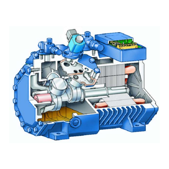
- Page 216 Features Impact Semi-Hermetic Reciprocating Compressors cover the whole application range regardless of whether traditional or chlorine-free HFC refrigerants are used. The latest innovation is the "C Series" which offer very compact size, universal application, minimum energy consumption, and very low vibration levels. All IR Impact compressors have the same robust valve plate construction, high quality wear...
- Page 217 Lubrication Impact compressors are supplied with two types of lubrication systems. C-Series compressors with the letters S or T in the model number have an Enhanced Centrifugal Lubrication system with no oil pump, while C-Series models with the letters P or Q in the model number, and all B-Series compressors have oil pumps.
- Page 218 Oil Pump Figure 1: IR Impact compressor IR4C2397P with Positive Displacement Lubrication To avoid frequent tripping, the oil pressure switch includes a time delay (usually 90 to 120 seconds) since the compressor starts with refrigerant dissolved in the oil, for example, the pump’s operation may be temporarily interrupted by vapor bubbles in the suction port.
- Page 219 Figure 2: IR Impact compressor IR4C2397S with Enhanced Centrifugal Lubrication Compared to commonly used splash lubrication, the new system has advantages with respect to its highly dynamic response characteristics: After starting, the oil flow is immediately present and maintained over the entire operating range. Oil carry over (% of mass flow) (Compressor IR4C0969, R404A, 40/120°F) Pump...
- Page 220 Oil Monitoring with Enhanced Centrifugal Lubrication The more difficult task was to develop a suitable monitoring system for the oil circuit. An oil control sensor (4) has been developed, which is mounted directly into the pocket (2). It utilizes a heated PTC element, which is cooled by the circulating oil.
- Page 221 If the differential oil pressure drops below the cutout pressure for more than 90 seconds, the output contact opens and stops the compressor. The control may be manually reset after approximately 3 minutes by pushing the reset button. The control’s internal microprocessor also integrates multiple time periods when low oil pressure is present, and may shut off the compressor even if 90 continuous seconds has not elapsed.
- Page 222 Johnson Controls P545NCB-25C Oil Pressure Control Technical Data Supply Voltage 120 or 240 VAC + 10%, - 15%. 50/60 Hz Power Consumption 3 VA Time Delay with Low Oil Pressure 90 +/- 12 seconds Control Relay Pilot duty 375 VA at 120VAC, 750 VA at 240 VAC Switch P400BD-1...
- Page 223 As an alternative to the Delta-P or the Johnson Controls P545, compressors with oil pumps may use an externally mounted oil differential pressure switch with tubing connections to compressor suction and the discharge of the oil pump. Applicable switches would include the Danfoss MP54 and the Johnson P128CA.
- Page 224 I-Cool - Supplemental Cooling Impact C-Series compressors may be equipped with the optional I-COOL system that provides an optimized cooling method for low and medium temperature, but is only applicable for compressor models IR2C0173 - IR4C1145. The position of the suction strainer may be changed as shown in the figures below.
- Page 225 Inject-Cool - Supplemental Cooling In addition to I-Cool, Inject-Cool is a further cooling method for larger single-stage low temperature R-22 compressors. Inject-Cool uses a liquid injection valve to inject liquid refrigerant directly into the compressor body whenever additional cooling is needed, as dictated by the discharge line temperature sensor.
- Page 226 Note: Do not use unloaders with Inject-Cool compressors. The following table lists Inject-Cool liquid injection valve models and part numbers: Compressor Model Inject Cool Valve Part Inject Cool Valve Model Number Number Number IR4C1480 0707532 Y1037-FV-1-240 IR4C1761 0707533 Y1037-FV-1 ½-240 IR4C2067 0707533 Y1037-FV-1 ½-240...
- Page 227 Discharge Mufflers Ingersoll-Rand Impact compressors are supplied with discharge mufflers cast into the cylinder heads (patent applied for), which significantly reduces discharge tubing vibration. Cylinder Head without Muffler Cylinder Head with Muffler Mechanical Design...
- Page 228 Capacity Control Four and six cylinder compressors offer integrated capacity control that makes use of the principle of suction shut-off. The following combinations are possible: Compressor Type Possible Unloaded Capacity Number of Unloaders 4-Cylinder 6-Cylinder 66% and 33% 8-Cylinder 75% and 50% In full-load operation the solenoid coil is de-energized, and suction gas flows to all cylinders.
- Page 229 Application limits with part-load operation With unloaders, compressor temperatures increase due to reduced refrigerant flow, reduced motor cooling, and electrical and mechanical losses. Therefore, the application ranges of compressors with unloaders are somewhat restricted. Please refer to the application envelopes when selecting compressors with unloaders.
- Page 230 Crankcase heaters should be selected based on the following table: Compressor Model Voltage IR Part Wattage Securing Number Number Method 110 V 0704640 IR2C0173 – IR2C0407 60W * Clip 230 V 0704641 110 V 0704642 IR2C0484 – IR4C1385 120W * Clip 230 V 0704643...
-
Page 231: Head Cooling Fans
Head Cooling Fans Head Cooling Fans: Fans are available for all compressor types upon request. The condenser air stream may be used in place of a head cooling fan if the air velocity over the compressor is at least 10 ft/sec at all operating conditions. The following table lists cooling fan parts: Compressor Model Mounting 120 Volt... - Page 232 Fan Mounting Bracket for IR4C0770 .. IR4C1385, Part. No. 0705467 Fan Mounting Bracket for IR4C1480 .. IR4C2397, Part. No. 0705466 Mechanical Design...
- Page 233 Fan Mounting Bracket for IR4B2707 .. IR4B3604, Part. No. 0705465 Fan Mounting Bracket for IR6B4060 .. IR6B6462, Part. No. 0705464 Mechanical Design...
- Page 234 Cylinder Heads Ingersoll-Rand Impact compressors use three types of cylinder heads. 1) Standard Head – no additional functions 2) Capacity Control cylinder heads are marked CR . 3) Start Unloader cylinder heads are marked SU . BE SURE TO APPLY THE CORRECT CYLINDER HEAD FOR THE INTENDED APPLICATION Minimum Space Requirements Ingersoll-Rand...
- Page 235 INGERSOLL-RAND Impact SEMI-HERMETIC RECIPROCATING COMPRESSORS INSTALLATION AND START-UP INSTRUCTIONS Installation and Start-up...
- Page 236 Operating Instructions. The following standards have procedures that should be followed when installing and operating Ingersoll Rand Impact semi-hermetic reciprocating compressors: Specific safety regulations and standards (UL 1995 and ANSI/ASHRAE 15), Generally acknowledged safety standards NFPA –...
- Page 237 The following instructions are prepared to aid the installation and/or service in providing an adequate installation with optimum performance. These instructions are general in nature, and have been written primarily for field installation of Ingersoll Rand Impact compressors.
- Page 238 Figure 1. Lifting the Compressor Installation – Mechanical Mounting The Ingersoll Rand Impact compressors may be rigidly mounted if no danger of breakage due to vibration exists in the associated piping system. For this purpose, place a washer between each compressor foot and frame. (Note: This washer is not required for compressor models IR4C1480 through IR4C2397.) Otherwise the compressor must be...
- Page 239 Figure 2. Anti-vibration mounts Installation – Electrical The supply power, voltage, frequency, and phase must coincide with the compressor nameplate. Ingersoll Rand Impact compressor models IR4C1480 and larger have dual voltage motors, care should be taken to assure proper connection of wiring within the terminal box.
- Page 240 For the electrical part of the installation, verify the following installed components match those listed in the Electrical section of this manual. 1. Wire sizes to handle the connected load 2. Circuit breaker size 3. Contactor size 4. Control circuit wiring, including high pressure safety controls, low pressure controls, and oil failure controls 5.
- Page 241 Leak Testing Evaluate the refrigeration circuit assembly according to ANSI/ ASHRAE 15 or valid equivalent safety standards. The following procedure is recommended for leak checking the refrigeration system prior to starting any compressor. 1. Visually inspect all lines and joints for proper piping practices. 2.
- Page 242 Evacuation Attention! Nitrogen and moisture will remain in the system unless proper evacuation procedures are followed. Nitrogen left in the system may cause excessive discharge pressure problems. Moisture causes TEV ice blockage, wax build up, acid oil, and sludge formation. Do not simply purge the system, this method is expensive, harmful to the environment, may leave moisture and nitrogen in the system, and may result in fines or penalties from the EPA.
- Page 243 Pre-Check, Charging and Start-up After the installation, leak testing, and evacuation procedures are complete the following items should be checked before charging the system with refrigerant: 1. Check all electrical connections to make sure they are tight. 2. Observe compressor oil levels; oil should be visible in the compressor sight glass.
- Page 244 9. Allow the full system to operate until it stabilizes. 10. Adjust all expansion valves, EPR valves, control valves, and other controls to their proper settings. 11. Re-check refrigerant charge and oil levels, adding refrigerant and oil as needed. Items to Watch and Check During Start-up Excessive Vibrations The whole system, especially the piping and capillary tubes must be designed to prevent abnormal vibrations.
-
Page 245: Oil Charge
After this initial change, it is recommended that the oil be replaced approximately every three years or 10,000 to 12,000 operating hours. Also replace the oil filter and clean the magnetic plug. Use only Ingersoll Rand approved lubricants as listed in the Lubricant – Section 8 of this manual. Attention! Ester oils are strongly hygroscopic. - Page 246 Troubleshooting - Procedures Warning! Before attempting any service work on the compressor, the following safety precautions should be strictly adhered to. Failure to follow these instructions could result in serious personal injury. Follow recognized safety practices and wear protective goggles. Do not operate compressor or provide any electric power to this unit unless the compressor terminal box cover is in place and secured.
- Page 247 Troubleshooting - Chart Observation Possible Cause Remedy Power off Check main switch, fuses, and wiring Current overload open Reset manually 1. Compressor will Oil safety switch open Reset manually not start Loose electrical Tighten connections. Check wiring connections or faulty wiring and rewire if necessary.
- Page 248 Observation Possible Cause Remedy Excessive water flow Adjust water regulating valve through condenser Suction service valve Open the valve partially closed 6. Low discharge pressure Leaky compressor suction Pump down, remove the valves cylinder head, examine valves and seats; replace if necessary Worn piston rings Replace compressor Improper system piping...
- Page 249 Observation Possible Cause Remedy Inadequately supported Support pipes or check pipe piping or loose pipe connections 10. Pipe rattle connections Low oil charge Check oil level requirements Faulty oil pump drive Replace segment 11. Oil pressure lower segment than normal or no oil Worn oil pump Replace bearing head assembly pressure...
- Page 250 Observation Possible Cause Remedy Check control box for Replace defective components. welded starter contacts, 14. Motor burnout welded overload contacts, or burned out heater elements. 15. On parallel Oil equalization line not Level oil equalization line compressor preventing gas equalization installations, oil level does not Excessive blow by into...
- Page 251 Troubleshooting - Motor Burnout (Clean-up Procedure) When a hermetic motor burns out, the stator winding decomposes forming carbon, water, and acid, which contaminate refrigerant systems. These contaminants must be removed from the system to prevent repeat motor failures. Warning! Before attempting any service work on the compressor, see safety precautions listed on page 12 of this section.
- Page 252 De-commissioning Standstill Keep the crankcase heater switched on until dismantling the compressor. This prevents increased refrigerant concentration in the compressor oil. Dismantling the compressor For repair work that makes compressor removal necessary, or when decommissioning: 1. Close the shut-off valves at the compressor. 2.
- Page 253 Polyolester Lubricant (IRPOE32) for Reciprocating Compressors with an HFC Refrigerant General Ingersoll-Rand reciprocating compressors that are intended for use with chlorine free HFC refrigerants (R404A, R507, etc.) shall be charged with a high quality polyolester lubricant. IR POE 32 lubricant was formulated specifically for this purpose. IRPOE32 polyolester lubricant provides good miscibility with HFC refrigerants, contrary to conventional mineral oils, and is therefore the choice of polyolester lubricants when using an HFC refrigerant.
- Page 254 Solubility Limits - IR POE 32 with R404A Immiscible Miscible % Oil by Weight Refrigerant Concentration in Lubricant IR POE32 and R-404A Oil Temperature F Lubricants...
- Page 255 For air conditioning (H-range) and liquid injection cooling with single stage compressors, the use of a POE lubricant with a higher basic viscosity is needed. Contact Hussmann Global Engineering for proper application. Crankcase heaters with a high capacity and in certain cases pump down control are required.
- Page 256 If the lubricant in the system is not listed, it is recommended that the lubricant be replaced with one on the list or contact Hussmann Global Engineering for further guidance. Consult the retrofit section of this catalog for proper retrofit procedures.
- Page 257 Mineral Oil (IRMO32) for Compressors with an Reciprocating HCFC Refrigerant General Ingersoll Rand reciprocating piston compressors for HCFC refrigerants are fitted as standard with special refrigeration lubricant type Ingersoll Rand MO32. Its features include: Thermal stability Low tendency to foam...
- Page 258 These lubricants are for use with HCFC refrigerants. Viscosity Supplier Oil Type Application Range Original Charge Ingersoll Rand RMO32 H M L Alternative Oils Energol LPTF 32 H M (L) Energol LPTF 46 Icematic 266...
- Page 259 Lubrication Table, lost lubricant may be replaced with that lubricant. If the lubricant in the system is not listed, it is recommended that the lubricant be replaced with one on the list or contact Hussmann Global Engineering for further guidance. Consult the retrofit section of this manual for proper retrofit procedures.
- Page 261 ™ INGERSOLL RAND Impact SEMI HERMETIC RECIPROCATING COMPRESSOR Model Number Nomenclature IR 4 C 0000 S B Voltage B – 208-230/460/3/60 K – 208/230/3/60 M – 460/3/60 P – 575/3/60 R – 208/230/1 /60 Oil System S – Enhanced Centrifugal P –...
- Page 262 Aftermarket Compressor Part Numbers IR Impact Hussmann Service Part Service Core Part Compressor Aftermarket Part Voltage Number Number Model Number Number IR2C0173SK CU.8420421 8420421 208-230/3 CU.C420421 IR2C0173SM CU.8420422 8420422 460/3 CU.C420422 IR2C0173SP CU.8420423 8420423 575/3 CU.C420423 IR2C0173SR CU.8420367 8420367 208-230/1 CU.C420367...
- Page 263 IR Impact Hussmann Service Part Service Core Part Voltage Compressor Aftermarket Part Number Number Model Number Number IR4C0969SM CU.8420386 8420386 460/3 CU.C420386 IR4C0969SP CU.8420387 8420387 575/3 CU.C420387 IR4C0969TK CU.8420473 8420473 208-230/3 CU.C420473 IR4C0969TM CU.8420474 8420474 460/3 CU.C420474 IR4C0969TP CU.8420475 8420475 575/3 CU.C420475...
- Page 264 IR Impact Hussmann Service Part Service Core Part Voltage Compressor Aftermarket Part Number Number Model Number Number IR4B3604QP CU.8420500 8420500 575/3 CU.C420500 IR6B4060PB CU.8420413 8420413 208-230/460-3 CU.C420413 IR6B4060PP CU.8420414 8420414 575/3 CU.C420414 IR6B4060QB CU.8420501 8420501 208-230/460-3 CU.C420501 IR6B4060QP CU.8420502 8420502 575/3 CU.C420502...
- Page 265 ™ Impact Compressor – 4 hour Distribution Map Aftermarket...
- Page 266 Responsible for the Quality of Manufactured (770) 291-2390 Service Manager Products (IR IMPACT compressor and the Refrigeration System Solution Package RSS) produced at The Hussmann Suwanee Facility Ken Hughes Customer Service / Provides Factory support for (IR IMPACT (770) 291-2984...
- Page 267 Alfred Gutierrez Field Service Engineer, Provides field support for the IR IMPACT (817) 819-1498 compressor installed in Hussmann OEM equipment Dave Hampton Field Service Engineer, Provides field support for the IR IMPACT (636) 236-2538 compressor installed in Hussmann OEM equipment...
- Page 268 Compressor Model Cross Reference Table ™ Copeland Model Carlyle Model Impact Compressor CFH Unld Model Number Number Number IR2C0173SK KAGA-010A-TAC-800 IR2C0173SK KAGA-010E-TAC-800 IR2C0173SK KAGA-015A-TAC-800 IR2C0173SK KAMA-007A-TAC-800 IR2C0173SK KAMA-007E-TAC-800 IR2C0173SK KAMA-010A-TAC-800 IR2C0173SK KARA-010E-TAC-800 IR2C0173SM KAGA-015A-TAD-800 IR2C0173SM KAM1-010A-TAD-800 IR2C0173SM KARA-011E-TAD-800 IR2C0222SK KAJA-010A-TAC-800 IR2C0222SK KAJA-011A-TAC-800 IR2C0222SK...
- Page 269 ™ Impact Compressor Copeland Model Carlyle Model CFH Unld Number Number Model Number IR2C0692SM NRB2-040E-TFD-800 IR2C0692SP LAHA-032A-TAE-800 IR2C0692SP LAHA-032E-TAE-800 IR4C0770SK 2DC3-0500-TFC-800 06DM3130CA3200 IR4C0770SK 2DC3-050E-TFC-800 06DM3130CA3200 IR4C0770SK LACA-032E-TAC-800 06DR0130CA3200 IR4C0770SK LALA-032E-TAC-800 06DR0130CA3200 IR4C0770SK NRA2-050A-TFC-800 06DM3130CA3200 IR4C0770SK NRD1-032E-TFC-800 06DR0130CA3200 IR4C0770SM 2DC3-0500-TFD-800 06DM3130CA3600 IR4C0770SM 2DC3-050E-TFD-800 06DM3130CA3600...
- Page 270 ™ Impact Compressor Copeland Model Carlyle Model CFH Unld Number Number Model Number IR4C1480SB 1480 3DE3A0750-TFC-800 1371 06DA824DA3270 1435 IR4C1480SB 1480 3DE3A0750-TFD-800 1371 06DA824DA3670 1435 IR4C1480SB 1480 3DE3A0750-TFD-800 1371 06DA824DA3670 1435 IR4C1480SB 1480 3DE3A075E-TFC-800 1371 06DA824DA3200 1435 IR4C1480SB 1480 3DE3A075E-TFC-800 1371 06DA824DA3200 1435...
- Page 271 ™ Impact Compressor Copeland Model Carlyle Model CFH Unld Number Number Model Number IR4C1761SB 1761 3DPHA100E-TFD-800 1615 06DA328DA3670 1680 IR4C1761SB 1761 9RC1-101A-TFC-800 1615 06DA328DA3200 1680 IR4C1761SB 1761 9RC1-101A-TFC-800 1615 06DA328DA3200 1680 IR4C1761SB 1761 9RC1-101A-TFD-800 1615 06DA328DA3600 1680 IR4C1761SB 1761 9RC1-101A-TFD-800 1615 06DA328DA3600 1680...
- Page 272 ™ Impact Compressor Copeland Model Carlyle Model CFH Unld Number Number Model Number IR4C2397SB 2397 3DS3A150E-TFC-800 2127 06DM337DA3200 2225 IR4C2397SB 2397 3DS3A150E-TFD-800 2127 06DM337DA3600 2225 IR4C2397SB 2397 3DS3A150E-TFD-800 2127 06DM337DA3600 2225 IR4C2397SB 2397 3DT3A1500-TFC-800 2127 06DM337DA3270 2225 IR4C2397SB 2397 3DT3A1500-TFC-800 2127 06DM337DA3270 2225...
- Page 273 ™ Impact Compressor Copeland Model Carlyle Model CFH Unld Number Number Model Number IR4B3604PB 3604 4DT3-220E-FSD-800 3603 IR4B3604PB 3604 4DT3-220E-TSK-800 3603 IR4B3604PB 3604 4RJ1-300A-FSD-800 3603 IR4B3604PB 3604 6RN2-300A-TSK-800 3580 IR4B3604PP 3604 4DR3-3000-TSE-800 3603 IR6B4060PB 4060 06EM265300 4096 IR6B4060PB 4060 06EM765300 4096 IR6B4060PB 4060...
- Page 274 ™ Impact Compressor Copeland Model Carlyle Model CFH Unld Number Number Model Number IR6B5406PB 5406 6DS3-4000-FSD-800 5407 IR6B5406PB 5406 6DS3-4000-FSU-800 5407 IR6B5406PB 5406 6DS3-4000-TSN-800 5407 IR6B5406PB 5406 6DS3-400E-TSN-800 5407 IR6B5406PB 5406 6DT3-300E-FSD-800 5407 IR6B5406PB 5406 6DT3-300E-TSK-800 5407 IR6B5406PB 5406 6RS2-400A-FSD-800 5404 IR6B5406PB 5406...
- Page 275 ™ Impact Compressor Parts List Sight Glass Head Gasket Valve Plate Gasket Valve Plate Complete Gasket Compressor Part # Part # Item # Part # Item # Part # Item # Item # IR2C0173S GA.4330120 GA.4330148 CU.4220142 GA.4330126 IR2C0222S GA.4330120 GA.4330149 CU.4220143 GA.4330126...
- Page 276 Sight Glass Compressor Gasket Kit Suction Service Valve Discharge Service Valve IR Compressor Part # Item # Part # Item # Part # Item # Part # Item # IR2C0173S SG.4220131 GA.4330162 CU.4220166 CU.4220160 IR2C0222S SG.4220131 GA.4330163 CU.4220166 CU.4220160 IR2C0278T SG.4220131 GA.4330112 CU.4220166...
- Page 277 Suction Valve Discharge Valve Suction Valve Discharge Valve Gasket to Body Gasket to Body Gasket to Collar Gasket to Collar Compressor Part # Item # Part # Item # Part # Item # Part # Item # IR2C0173S GA.4330131 GA.4330114 #N/A #N/A IR2C0222S...
- Page 278 Electrical Terminal Electrical Thermistor Plate Plate Gasket Seals / Connection Plate Gasket Compressor Part # Item # Part # Item # Part # Item # Part # Item # IR2C0173S CU.4440337 GA.4330118 CU.4440340 GA.4330137 IR2C0222S CU.4440337 GA.4330118 CU.4440340 GA.4330137 IR2C0278T CU.4440337 GA.4330118 CU.4440340...
- Page 279 Oil Pump Gasket Oil Pump Plug/ Sensor Motor Protector Oil Pump to Body Gasket Module SE-B 230V Compressor Item # Item # Part # Item # Part # Item # Part # Part # IR2C0173S #N/A #N/A #N/A #N/A #N/A #N/A CU.4220114 IR2C0222S...
- Page 280 Motor Protector Module SE-B 115V Compressor Part # Item # IR2C0173S CU.4220117 IR2C0222S CU.4220117 IR2C0278T CU.4220117 IR2C0278S CU.4220117 IR2C0323S CU.4220117 IR2C0407T CU.4220117 IR2C0407S CU.4220117 IR2C0484T CU.4220117 IR2C0484S CU.4220117 IR2C0572T CU.4220117 IR2C0572S CU.4220117 IR2C0692T CU.4220117 IR2C0692S CU.4220117 IR4C0770T CU.4220117 IR4C0770S CU.4220117 IR4C0969T CU.4220117 IR4C0969S...
- Page 281 ™ Impact Compressor Accessory Parts List Crankcase Heater Crankcase Heater Capacity Control Capacity Control 230V 115V Head Stem Compressor Part # Item # Part # Item # Part # Item # Part # Item # IR2C0173S HE.4850332 HE.4950325 #N/A #N/A #N/A #N/A IR2C0222S...
- Page 282 Capacity Control Coil Capacity Control Coil Oil Protection Oil Protection Sensor 115-1-60 208-220-1-60 Module Compressor Item # Item # Part # Item # Part # Item # Part # Part # IR2C0173S #N/A #N/A #N/A #N/A #N/A #N/A #N/A #N/A IR2C0222S #N/A #N/A...
- Page 283 Refrigeration Lubricant Kits Service Part Hussmann Aftermarket Description Number Part Number CL.4610786 4610786 OIL MINERAL 3GS 1 GALLON 4610787 CL.4610787 OIL MINERAL 3GS 5 GALLON 4610788 CL.4610788 OIL MINERAL 4GS 1 GALLON 4610789 CL.4610789 OIL MINERAL 4GS 5 GALLON 4610790 CL.4610790...
- Page 284 HUSSMANN AFTERMARKET ™ IR IMPACT COMPRESSOR RETROFIT PARTS LIST IR4C to 3D ADAPTER KITS (Required when using existing piping, based on model type) Service Part # Description CU.4220171 Kit Adapter 3D 2 bolt to 2 bolt CU.4220172 Kit Adapter 3D 2 bolt to 4 bolt CU.4220173...
- Page 285 Compressor Exploded View IR2C0173 to IR4C1385 Aftermarket...
- Page 286 Compressor Optional Heads -- Exploded View IR2C0173 to IR4C1385 Aftermarket...
- Page 287 Compressor Exploded View IR4C1480 to IR4C2397 Aftermarket...
- Page 288 Compressor Optional Heads -- Exploded View IR4C1480 to IR4C2397 Aftermarket...
- Page 289 Compressor Exploded View IR4B2707 to IR6B6462 Aftermarket...
- Page 290 Compressor Optional Heads -- Exploded View IR4B2707 to IR6B6462 Aftermarket...
- Page 291 Compressor Exploded View IR8C7863 to IR8C9400 Aftermarket...
- Page 292 Compressor CR Head Exploded View IR8C7863 to IR8C9400 Aftermarket...
- Page 293 Retrofit Check Lists On the following pages are two forms that were developed to help ensure a successful retrofit with an IR Impact compressor. IR Impact Retrofit Survey Check List This form is intended for use in the planning stages of the retrofit process. It is to be used to gather information about the existing compressor and rack installation to ensure that the proper parts will be ordered and important piping and clearance issues are addressed prior to ordering a replacement compressor.
- Page 294 RETROFIT TO IMPACT IMPACT COMPRESSOR EXISTING SYSTEM CHECK SHEET Location Name: _____________________________ City : _______________________ State:_____ System Manufacture: _________________________ Rack / Unit ID _____ MFG. DATE: ___/___/__ UNIT MODEL NUMBER:________________________ UNIT SERIAL NUMBER: __________________ REFRIGERANT TYPE: _____ RACK VOLTAGE: ______________ CONTROL VOLTAGE: _________ TYPE RETROFIT: Copeland 3D To IR4C _______...
- Page 295 EXISTING SYSTEM CHECK SHEET p.2 Suction Valve Type 2 Bolt 4 Bolt Discharge Service Valve Valve On Compressor Flange & Roto-Lock Top Mounted Front Mounted Head Cooling Fan Clearance: ___________ inch. How Much Clearance Is There ? Top Of Head Cooling Fans To Bottom Of Control Panel REASON FOR EXISTING COMPRESSOR FAILURE Mechanical: ________ Electrical:...
- Page 296 RETROFIT TO IMPACT IMPACT COMPRESSOR REPLACEMENT COMPRESSOR CHECK SHEET Location Name: _____________________________ City : _______________________ State:_____ System Manufacture: _________________________ Rack / Unit ID _____ MFG. DATE: ___/___/__ UNIT MODEL NUMBER:________________________ UNIT SERIAL NUMBER: __________________ REFRIGERANT TYPE: _____ OIL TYPE: ______________ CONTROL VOLTAGE: _________ NEW COMPRESSOR INFORMATION MODEL NUMBER:...
- Page 297 Aftermarket...
- Page 298 CORE ACCOUNT # 3RCORECPN FORM # 4150191 NO POSTAGE NECESSARY IF MAILED IN THE UNITED STATES BUSINESS REPLY MAIL FIRST-CLASS PERMIT NO.4203 MINNEAPOLIS, MN 55420 POATAGE WILL BE PAID BY ADDRESSEE HUSSMANN AFTERMARKET CUSTOMER SERVICE 314 WEST 90 STREET MINNEAPOLIS, MN 55420-9859 Aftermarket...
- Page 300 Reliability and Performance IR Impact Compressors are designed for years of trouble free service. An advanced slinger oil system reduces oil carry over and increases efficiency. The compressor uses a single casting with no bottom cover, eliminating bottom bolts that may leak.
- Page 301 With two standard base rails and a simple adapter kit, your new IR Impact Compressors can be easily and quickly installed to get your systems back up and running smoothly with the latest compressor technology. Contact your local Hussmann Service Branch for purchase information.
- Page 302 IR Ingersoll-Rand 12999 St. Charles Rock Rd. Bridgeton, MO 63044-2483 (314) 291-2000 Printed in U.S.A. Cat. IR Impact Compressor 0604...
- Page 303 COPELAND to IR IMPACT™ COMPRESSOR 3D Adapter Kits Service Hussmann Copeland Model # CFH IR Model # Part # AM # Description 3DA3A0500-TFC-800 1371 IR4C1480PB 1480 CU.4220171 4220171 Kit Adapter 3D 2 bolt to 2 bolt 3DA3A0500-TFC-800 1371 IR4C1480SB 1480 CU.4220171...
- Page 304 Service Hussmann Copeland Model # CFH Model # CFH Part # AM # Description 3DE3A0750-TFC-800 1371 IR4C1480SB 1480 CU.4220171 4220171 Kit Adapter 3D 2 bolt to 2 bolt 3DE3A0750-TFD-800 1371 IR4C1480PB 1480 CU.4220171 4220171 Kit Adapter 3D 2 bolt to 2 bolt 3DE3A0750-TFD-800 1371 IR4C1480SB 1480 CU.4220171...
- Page 305 Service Hussmann Copeland Model # CFH Model # Part # AM # Description 3DH3A060E-TFC-800 1371 IR4C1480SB 1480 CU.4220171 4220171 Kit Adapter 3D 2 bolt to 2 bolt 3DH3A060E-TFD-800 1371 IR4C1480PB 1480 CU.4220171 4220171 Kit Adapter 3D 2 bolt to 2 bolt...
- Page 306 Service Hussmann Copeland Model # CFH Model # Part # AM # Description 3DP3A1000-TFD-800 1615 IR4C1761SB 1761 CU.4220171 4220171 Kit Adapter 3D 2 bolt to 2 bolt 3DP3A100E-TFC-800 1615 IR4C1761PB 1761 CU.4220171 4220171 Kit Adapter 3D 2 bolt to 2 bolt...
- Page 307 Service Hussmann Copeland Model # CFH Model # Part # AM # Description 3DT3A0750-TFD-800 2127 IR4C2397SB 2397 CU.4220172 4220172 Kit Adapter 3D 2 bolt to 4 bolt 3DT3A1000-TFC-800 2127 IR4C2397PB 2397 CU.4220172 4220172 Kit Adapter 3D 2 bolt to 4 bolt...
- Page 309 Sight Glass O-ring 1/2”-13X1 1/2” Bolts Wire Lug # 4-# 6 1” -90° EMT Fitting Discharge Flange Gasket 1 ¼” X 1” Reducer Washer 1 3/4”-12 Teflon Gasket Discharge Goose Neck 12”-3/8 Flare Hose Hussmann Aftermarket 1/13/06 Page 1 of 19...
- Page 310 3/4 “ Wrench Service Wrench Razor Knife Philips Head Screw Driver 10. Straight Slot Screw Driver 11. Large Channel Lock Pliers (QTY 2) 12. Hammer 13. 10” Adjustable Wrench 14. Wire Cutters & Strippers Hussmann Aftermarket 1/13/06 Page 2 of 19...
- Page 311 Remove oil float by tilting the compressor away from the oil sight glass. Unbolt IR4C the oil float assembly, leaving the compressor tilted until the sight glass from the be installed on the 3D compressor. Figure 2 Hussmann Aftermarket 1/13/06 Page 3 of 19...
- Page 312 3. Compressor may be dry of oil, if not, tilt compressor away from sight glass. Remove sight glass and Install oil float using the sight glass bolts and new o-ring (H). Figure 5 Figure 6 Hussmann Aftermarket 1/13/06 Page 4 of 19...
- Page 313 4. Install all the required fittings removed from the old compressor. See Figure 7 compressor fitting locations Figure 7 Hussmann Aftermarket 1/13/06 Page 5 of 19...
- Page 314 (S ) Install suction adapter to the C4 compressor with the 4 cap screws (V) provided in the kit. Figure 8c Position the adapter with the throat angle down. Tighten the 4 cap screws evenly. Hussmann Aftermarket 1/13/06 Page 6 of 19...
- Page 315 Rail (B)- marked (Right Front) mounts to right side with the relief facing down 8. Place compressor on rails and secure with the 1/2”-13 x 1 1/2” bolt (C) and1/2” washers (G). Figure 11 Hussmann Aftermarket 1/13/06 Page 7 of 19...
- Page 316 Rota-lock nut with the other channel lock pliers. Figure 13 11. Connect oil line to oil float using hose provided in kit. 12. Connect all remaining lines and controls to the compressor. Figure 14 Hussmann Aftermarket 1/13/06 Page 8 of 19...
- Page 317 If the hole is oversized for the connector, use the reduction washers (E) with the 1” connector. Figure 17 Hussmann Aftermarket 1/13/06 Page 9 of 19...
- Page 318 Jumpers for 208/230 V (3 needed for 460 V) Flat Washers Hex nuts Lugs NOTE: For Direct-Start all parts received may not be needed. Please disregard any extra parts. To start remove nuts and washers holding the cap. Figure 20. Hussmann Aftermarket 1/13/06 Page 10 of 19...
- Page 319 . Add lugs to 1, 2, and 3. Mount one . Add cover and center Figure 23 Figure 24 washer on each lug. Place nuts on all terminals washers and nuts. tighten to 4.4 ft-lb. Hussmann Aftermarket 1/13/06 Page 11 of 19...
- Page 320 6-9. Mount lugs on terminals 1, 2, and 3. Add one flat washer on each lug and install nuts on all terminals. Torque to 4.4 ft-lb. . Add cover, center washers and nuts. Figure 27 Hussmann Aftermarket 1/13/06 Page 12 of 19...
- Page 321 F ie ld In s ta lle d W ire T h e rm isto r J u m p er T e rm in a ls Figure 29 Wiring SE-B1 Motor Overload Module Hussmann Aftermarket 1/13/06 Page 13 of 19...
- Page 322 SE-B1 Motor Protector Module SE-B2 Motor Protector Module Also shown are the included connectors for the M1 and M2 posts in the terminal box Figure 30 INT69/70 Motor protector and Oil Monitoring Module Figure 31 Hussmann Aftermarket 1/13/06 Page 14 of 19...
- Page 323 4. Mount the INT 69/70 sensor in the compressor housing as shown in Figure 37. Wire the INT 69/70 and sensor into the compressor control circuit according to the wiring diagram in Figure 36. Figure 34 Hussmann Aftermarket 1/13/06 Page 15 of 19...
- Page 324 2 4 V o lt T ra n sfo rm er 5 0 V A Tem p S ensor Field Installed W ire Figure 36. Retrofit With INT 69/70 Overload Module With Oil Control Hussmann Aftermarket 1/13/06 Page 16 of 19...
- Page 325 17. To reset the INT 69/70 after an oil failure trip, the 24V power to the control must be interrupted. A pushbutton momentary switch is shown on the line side of the transformer as an option for this purpose. Figure 37 Hussmann Aftermarket 1/13/06 Page 17 of 19...
- Page 326 40. Requires Bracket # BR.4220261. 4. The complete head cooling fan kits which include the fan, motor and brackets are: CU. 4220215 for 120 volt CU.4220220 for 208/230 volt CU.4220225 for 460 volt Hussmann Aftermarket 1/13/06 Page 18 of 19...
- Page 327 KIT INJECT COOL 208V IR4C1761-IR4C2067 CU.4220202 KIT INJECT COOL 208V IR4C2397-IR4B3139 CU.4220203 KIT INJECT COOL 208V Inject Cool Valves Only IR4C1480 CU.4220208 INJECT COOL Valve IR4C1761-IR4C2067 CU.4220209 INJECT COOL Valve IR4C2397-IR4B3139 CU.4220210 INJECT COOL Valve Hussmann Aftermarket 1/13/06 Page 19 of 19...
- Page 329 19 mm socket Philips Head Screwdriver 24mm socket Large Channel Lock Pliers 10 mm Wrench Straight Slot Screwdriver 7/16” Wrench 10” Adjustable Wrench 9/16” Wrench Wire Cutters & Strippers 3/4“ socket Hammer 10. 15/16” socket Hussmann Aftermarket page 1 of 18 4/7/2006...
- Page 330 Unbolt the oil float assembly, leaving the compressor tilted until the sight glass from the IR ™ Impact can be installed on the 4D compressor. (3D compressor shown for demonstration purposes only.) Figure 1 Hussmann Aftermarket page 2 of 18 4/7/2006...
- Page 331 Leave terminal box cover in place. Refer to electrical connection section of manual Install all the required fittings removed from the old compressor to ™ IR Impact fitting locations (See Figure 4). Figure 4 Hussmann Aftermarket page 3 of 18 4/7/2006...
- Page 332 IMPORTANT DO NOT TIGHTEN THE MOUNTING BOLTS UNTIL BOTH SUCTION AND DISCHARGE VALVES ARE ALIGNED AND TIGHT Spacer Washers Figure 6 Figure 7 Figure 8 Oil Float Adapter Oil Float Hussmann Aftermarket page 4 of 18 4/7/2006...
- Page 333 Bolts (E) provided in the kit. Remove the service valve and place the blank off plate in the position of the service valve using the existing bolts. Figure 10 Hussmann Aftermarket page 5 of 18 4/7/2006...
- Page 334 Screw them into the flange about 1 -2 turns. Center the gasket between the suction spacer and the suction valve with a screwdriver while lifting up on the valve. Tighten the suction valve bolts evenly. Figure 12 Hussmann Aftermarket page 6 of 18 4/7/2006...
- Page 335 Attach the two thermistor wires to the sensor connectors using a 7mm nut driver or socket. Refer to the wiring diagram in Figure 27 for connections for the motor protector. Figure 14. Hussmann Aftermarket page 7 of 18 4/7/2006...
- Page 336 Figure 15 PLEASE NOTE: The compressor may have additional parts that are used for part winding start. Disregard the extra parts if you receive them. Figure 16 IR4B Compressor Terminals Prior to Starting Hussmann Aftermarket page 8 of 18 4/7/2006...
- Page 337 Fig.20 Nuts on 4, 5, and 6. Lugs on 1,2, and 3. Fig.21 Nuts on 7, 8, and 9 and on top of lugs on 1, 2, and 3. Torque all nuts to 7.4 ft-lb. Hussmann Aftermarket page 9 of 18 4/7/2006...
- Page 338 460-Volt Connection Instructions Fig.22 Three smaller jumpers on 4-7, 5-8, and 6-9. Fig.23 Insulator on 1-2-3. Fig.24 Lugs on 1, 2, and 3. Fig.25 Nuts on all terminals and torque to 7.4 ft-lb. Hussmann Aftermarket page 10 of 18 4/7/2006...
- Page 339 CU.4220233 INT69/70 SE-B1 Motor Protector Module SE-B2 Motor Protector Module Also shown are the included connectors For the M1 and M2 posts in the terminal box INT69/70 Motor protector and Oil Monitoring Module Hussmann Aftermarket page 11 of 18 4/7/2006...
- Page 340 Low Pressure Control Control 240V P545 Switch SE-B Protection Device Alarm Out Reference to line number in text Field Installed Wire Thermistor jumper Terminals Figure 27. SE-B Overload Module and Johnson P545 Oil Control Hussmann Aftermarket page 12 of 18 4/7/2006...
- Page 341 It is possible to use the switch from the P545 (the P400BD-1C) with the Sentronic module, although the timeout will approach 120 seconds instead of the 90 seconds in the P545 specifications. Figure 28. P545 Oil Control Figure 29. P545 Switch Installed Hussmann Aftermarket page 13 of 18 4/7/2006...
- Page 342 P ro te ctio n D e vice A larm O u t F ie ld In sta lle d W ire T h erm istor J um p er T erm in a ls Figure 30 Hussmann Aftermarket page 14 of 18 4/7/2006...
- Page 343 Retain the metal gasket to be Figure 31. used with the sensor. If the gasket is not metal it will leak. Figure 19 Figure 20 Oil Sensor Plug Figure 32 Figure 33 Hussmann Aftermarket page 15 of 18 4/7/2006...
- Page 344 Connect the black wire from the Delta-P oil failure control to line (L2). Connect the thermistor wires (1,2) to the compressor thermistor terminals. Once all the connections have been transferred to the new control device, the old controls can be removed. Hussmann Aftermarket page 16 of 18 4/7/2006...
- Page 345 3 screws provided with the existing fan. Wiring the fan will be the same as the previous compressor. Complete Fan Assembly Kits CU.4220216 120 volt Figure 35 CU.4220221 208-230- volt CU.4220226 460 volt Hussmann Aftermarket page 17 of 18 4/7/2006...
- Page 346 KIT INJECT COOL 208V IR4B3604-IR6B4060 CU.4220204 KIT INJECT COOL 208V Inject Cool Valves Only IR4C1480 CU.4220208 INJECT COOL Valve IR4C1761-IR4C2067 CU.4220209 INJECT COOL Valve IR4C2397-IR4B3139 CU.4220210 INJECT COOL Valve IR4B3604-IR6B4060 CU.4220211 INJECT COOL Valve Hussmann Aftermarket page 18 of 18 4/7/2006...