Table of Contents
Advertisement
Quick Links
Advertisement
Chapters
Table of Contents
Troubleshooting

Related Manuals for ADTRAN MX2820


Summary of Contents for ADTRAN MX2820
- Page 1 ® MX2820 System Manual Document Number: 61186003L1-1D October 2007...
- Page 2 In no event will ADTRAN be liable for any special, incidental, or consequential damages or for commercial losses even if ADTRAN has been advised thereof as a result of issue of this publication.
- Page 3 3. The name of the author may not be used to endorse or promote products derived from this software without specific prior written permission. THIS SOFTWARE IS PROVIDED “AS IS” AND ANY EXPRESS OR IMPLIED WARRANTIES, INCLUDING, BUT NOT LIMITED TO, THE IMPLIED WARRANTIES OF MERCHANTABILITY AND FITNESS FOR A PARTICULAR PURPOSE ARE DISCLAIMED.
- Page 4 3. Neither the name of the project nor the names of its contributors may be used to endorse or promote products derived from this software without specific prior written permission.
-
Page 5: Revision History
This font indicates references to other documentation and is also used for emphasis. indicates on-screen messages and prompts. This font indicates text to be typed exactly as shown. - Page 6 For detailed compliance information, refer to the compliance notice packaged with the specific product. RoHS Complaint This issue of this document includes RoHS compliant products. The products listed in the following table meet the EU's RoHS Directive 2002/95/EC and/or applicable exemptions. See www.adtran.com for further information on RoHS/WEEE.
-
Page 7: About This Manual
MX2820 system. This manual is arranged so that needed information can be quickly and easily found. The following is an overview of the contents. - Page 8 MX2820 System Manual Section 8 Trouble Analysis Procedures This section provides information to assist in locating and identifying alarm conditions. Appendix A Abbreviations and Acronyms Appendix B Warranty viii 61186003L1-1D...
- Page 9 IXL-001 Task Index List Find the Required Task in the List Below: For details, refer to: Installation Shelf and SCU Installation NTP-001 Unpack and Inspect Shelf DLP-500 Mount Shelf, Heat Baffle, and Fan DLP-501 Remove and Re-install Metal Cover DLP-502...
- Page 10 MX2820 System Manual Find the Required Task in the List Below: For details, refer to: Acceptance Test MX2820 Acceptance Test Procedure DLP-601 MUX Module Acceptance Test Procedure DLP-602 STS-1 MUX Acceptance Test Procedure DLP-603 Provisioning Logging on to the System...
- Page 11 Common Accessories for either shelf ........
-
Page 12: Table Of Contents
Telnet, SNMP, TFTP, and SSH over 10/100Base-T........ - Page 13 Vertical and Horizontal Space Requirements ........
- Page 14 DS3 Far-End Daily Thresholds and Alarms ........5-48 DS3 Far-End Quarter Hourly Thresholds and Alarms ....... 5-49 Viewing T1/E1 PM Statistics.
- Page 15 VT/Port Near-End Daily Thresholds and Alarms ........
-
Page 16: Autosave Filename Prefix, Autosave Filename Suffix, And Max Autosave
Provisioning System Configuration Archive (SCA) ........ - Page 17 Provisioning Simple Network Management Protocol ........5-132...
- Page 18 Accessing the IP Service Ports Access Control Menu ....... . .
- Page 19 Fan Assembly (One-to-One Cooling, Pusher Fan) ....... . . 7-14...
- Page 20 Wire Wrap ACO Posts ............7-39 Wire Wrap AUX3, AUX2, and AUX1 Alarm Input Posts......7-39 Wire Wrap MAJ and CRIT Alarm Relay Posts .
- Page 21 DS1 Daisy-chain to DS3 (Hard) Loopback........
- Page 22 Make RS-485 Bus Connections Between Shelves ........
- Page 23 Verifying Fan Module Alarm Connection to the SCU ....... .
- Page 24 Provision MUX Module Loopback Timeout ........
- Page 25 Observe the Alarm LED Status on the MUX Module ....... .
- Page 26 STS-1 VT/Port Alarm Condition Descriptions ........
- Page 27 7-foot Bay MX2820 Shelf Installation - Passively Cooled ....... 2-14...
- Page 28 Figure 5-57. BERT Pattern Selection Screen - For P/N 1186002L3 Only ......
- Page 29 Figure 5-87. Provisioning Menu, IP Forwarding, Remote System........
- Page 30 Figure 7-44. Account Properties/Access Privileges Screen ........
- Page 31 Figure 7-71. RADIUS Server Provisioning Menu........
- Page 32 Heat Dissipation for Fully Loaded M13 System at –48 VDC......2-7...
- Page 33 IP Service Ports Access Control Menu Descriptions........
- Page 34 MX2820 System Manual This page is intentionally blank. xxxiv 61186003L1-1D...
-
Page 35: System Description
Common Accessories for either shelf ........ - Page 36 MX2820 Multiplexer System Configuration ........
-
Page 37: Introduction
The ADTRAN MX2820 high-density M13/STS-1 multiplexer system offers bandwidth consoli- dation at a low cost in a dense rackmount chassis. The MX2820 gives customers the ability to easily install M13 or STS-1 modules on an “as needed” basis by simply inserting additional modules. -
Page 38: Warranty
MX2820 System Manual • Local and network timing • Provides powering options for –48 VDC or ±24 VDC systems • 19-inch or 23-inch versions available • Industry-leading 10-year warranty • NEBS Level 3, UL 60950, GR-1089-CORE compliant SYSTEM COMPONENTS The MX2820 system provides the following shelf units: •... -
Page 39: Mx2820 Shelf (19-Inch Or 23-Inch)
Section 1, System Description - System Components MX2820 Shelf (19-inch or 23-inch) This system consists of either a 19-inch wide or 23-inch wide by 3.5-inch high (2U) shelf. The 19-inch shelf can house seven redundant pairs of M13 or STS-1 MUX modules. The 23-inch shelf can house nine redundant pairs of M13 or STS-1 MUX modules. -
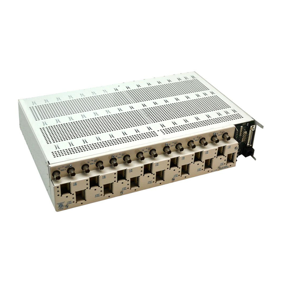
Page 40: Figure 1-1. Mx2820 19-Inch Shelf (Front And Rear View)
MX2820 System Manual Figure 1-1 shows the front and rear views for a MX2820 19-inch shelf. 1186011 1186003 1186002 1186002 1186002 1186002 1186002 1186002 1186002 1186002 1186002 1186002 1186002 1186002 1186002 1186002 STAT STAT STAT STAT STAT STAT STAT STAT... -
Page 41: Figure 1-3. Mx2820 Scu Front Panel
The System Controller Unit (SCU) provides the user interface and the network management interface for the MX2820 system. The user can provision and monitor the MUX modules either locally or remotely via the SCU. -
Page 42: Table 1-1. Mx2820 Scu Led Descriptions
Minor alarms • NEBS Level 3, UL 60950, GR-1089-CORE compliant • Operates over temperature range of –40°C to +50°C (no fans), –40°C to +65°C (with fans) • Derives power from redundant VDC supplied to the shelf SCU Front Panel LEDs Table 1-1 provides a description of each LED state for the SCU. -
Page 43: Figure 1-4. Mx2820 M13 Mux Module Front Panel
• Built-in 1:1 equipment redundancy • Multiplexes 28 DSX-1 (or 21 E1 channels) into a DS3 signal • De-multiplexes a DS3 signal into 28 DSX-1 or 21 E1 channels as allowed by DS2 framing • Supports the M13 or C-Bit parity DS3 formats •... -
Page 44: Table 1-2. Mx2820 M13 Mux Led Descriptions
• Detects and indicates DS3 alarm and loopback conditions • Local or loop timing modes • Operates over temperature range of –40°C to +50°C (no fans), –40°C to +65°C (with fans) • Manual and remote-initiated line and terminal loopback modes •... - Page 45 Solid Green Enabled DS1s normal (all okay) Solid Red Non-critical DS1 alarm in progress Flashing Red DS1 LOS on some enabled line (critical DS1 alarm; non- critical One-second Red system alarm) Single code violation or burst of code violations just...
-
Page 46: Figure 1-5. Mx2820 Clock Card, -48 Vdc
The MX2820 Clock Card is a plug-in card which generates a timing signal synchronized to either of two external BITS clock references. If both BITS clock references fail, the Clock Card will meet SONET Minimum Clock (SMC) holdover requirements to produce the clock reference. -
Page 47: Table 1-3. Mx2820 Clock Card Front Panel Leds
Section 1, System Description - System Components NOTE The MX2820 has two power options: –48VDC or ±24 VDC. The Clock Card operates at –48VDC only. Do not deploy a ±24 VDC system if Clock Cards are deployed for STS-1 MUX timing. Clock Card Front Panel LEDs Table 1-3 provides a description of the front panel LED. -
Page 48: Figure 1-6. Mx2820 Sts-1 Mux, -48 Vdc
MX2820 STS-1 MUX interfaces to a standard STS-1 signal from the network to provide 28 DSX-1 or 21 E1 outputs on the terminal side through the demapping of 28 VT1.5s or 21 VT2s. Two MX2820 MUX cards are used together to provide a redundant STS-1 multiplexer circuit. -
Page 49: Table 1-4. Mx2820 Sts-1 Mux Front Panel Leds
All DS1s are disabled DS1 STAT Green Enabled DS1s normal (all OK) Noncritical DS1 alarm (CAIS, LAIS) Flashing Red LOS on an enabled line (critical DS1 alarm; noncritical system alarm) Red (Flashing 1 sec per Single/Burst RX DS1 code violation event) Alternating Red/Green... -
Page 50: Table 1-5. Mx2820 Common Accessories
2”. The heat baffles are available to direct heat away from the equipment shelves. Fan modules and filters may be fitted to the heat baffles for improved cooling and density. The heat baffles and fan modules are available for both the 19-inch and 23-inch MX2820 shelves. -
Page 51: Table 1-6. 19-Inch Shelf Accessories
Section 1, System Description - System Components 19-inch Shelf The MX2820 system 19-inch shelf allows the use of the accessories shown in Table 1-6. Table 1-6. 19-inch Shelf Accessories Assembly Description Part Number Fan and Baffle Assembly Fan Module 1182006L1... -
Page 52: Table 1-8. Mx2820 Cabling Accessories
DS1 Connector to Stub – 1186021L3 DS1 Connector to Stub 1186025L1 1186025L2 DS1 Connector to Stub 1186050L1 1186050L2 DS1 Connector to Stub 1186100L1 1186100L2 DS1 Connector to Stub 1186150L1 1186150L2 Note: Custom-length cable assemblies can also be used. 1-18 61186003L1-1D... -
Page 53: Figure 1-7. Mx2820 Multiplexer System Configuration
The MX2820 system operates in local, loop (network), or external (BITS) timing mode. In the local timing mode, an onboard timing reference is provided. In the loop timing mode, the MUX modules synchronize with the received DS3 or STS-1 signal. Because the multiplexing/de- multiplexing process is asynchronous, each DS1 channel maintains its own Transmit and Receive timing. -
Page 54: Network Interfaces
The MX2820 system multiplexes DSX-1 or E1 input signals into DS3 or STS-1 output signals. Each MUX module accepts a single DS3 or STS-1 input signal from the network side and provides 28 DSX-1 or 21 E1 outputs. For 1:1 redundant system, the MX2820 system provides two MUX modules for each DS3 or STS-1 signal. -
Page 55: Environmental Alarm Inputs
For ACO, AUX1, AUX2, and AUX3A, alarms are activated when the circuit between the connecting posts is closed (a short appears across the line). For AUX3B, an alarm is activated by a cadenced input across the input posts; this input can be used to indicate a fan failure. - Page 56 MX2820 System Manual This page is intentionally blank. 1-22 61186003L1-1D...
-
Page 57: Engineering Guidelines
7-foot Bay MX2820 Shelf Installation - Passively Cooled ....... 2-14... - Page 58 Heat Dissipation for Fully Loaded M13 System at –48 VDC......2-7...
-
Page 59: Table 2-1. Mx2820 Equipment Dimensions And Weights
Section 2, Engineering Guidelines - Dimensions of Equipment DIMENSIONS OF EQUIPMENT Table 2-1 provides the dimensions of the MX2820 chassis, heat baffles, fan, and system modules. Table 2-1. MX2820 Equipment Dimensions and Weights Part Number Equipment (H x W x D) -
Page 60: Table 2-2. Current Draw Of Each Module At -48 Vdc
List series. Table 2-2 provides the current draw of each module at –48 VDC. For the M13 and STS-1 modules, this measurement was made with all T1s enabled and configured for maximum line length. A QRSS data pattern was utilized. -
Page 61: Table 2-4. Current Draw At -48 Vdc For Fully Loaded M13 System
M13 and STS-1 System Configurations Table 2-4 provides the current draw for a fully loaded M13 system at –48 VDC for a single 19- inch shelf and a single 23-inch shelf deployment. Table 2-4. Current Draw at –48 VDC for fully loaded M13 System... -
Page 62: Table 2-6. Current Draw At -48 Vdc For Fully Loaded Sts-1 System
Table 2-7 provides data for determining the wire gauge and fuse size for a fuse panel and MX2820 shelf in the same bay. The recommendations apply to wiring from the shelf to a fuse panel in the same bay. Table 2-7. Wire Gauge and Fuse Size Recommendations... -
Page 63: Table 2-8. Module Heat Dissipation At -48 Vdc
Note: x indicates the list version. Table 2-9 provides the heat dissipation for a fully loaded M13 system at –48 VDC for a single 19-inch shelf and a single 23-inch shelf deployment. Table 2-9. Heat Dissipation for Fully Loaded M13 System at –48 VDC... -
Page 64: Table 2-10. Heat Dissipation For Fully Loaded M13 System At ±24 Vdc
MX2820 System Manual Table 2-10 provides the heat dissipation for a fully loaded M13 system at ±24 VDC for a single 19-inch shelf and a single 23-inch shelf deployment. Table 2-10. Heat Dissipation for Fully Loaded M13 System at ±24 VDC... -
Page 65: Configuration Guidelines For The Mx2820 System
• Passively cooled: – Working from the bottom of the bay, leave a 1U space between the bottom of the rack and the first shelf. Install a MX2820 Chassis (P/N 1186001L1). – Leave a 1U space. Install a 1U passive heat baffle (Newton P/N 0040780114). - Page 66 MX2820 System Manual • Passively cooled: – Working from the bottom of the bay, leave a 1U space between the bottom of the rack and the first shelf, install a MX2820 shelf (P/N 1186001L2). – Leave a 1U space, install a 1U passive heat baffle (P/N 1180002L1).
-
Page 67: Table 2-12. Heat Dissipation For Shelf
Shelf Level NEBS further provides specific objectives for heat dissipation within a shelf in paragraph O4-12 of GR-63-CORE. For an equipment shelf such as the , the relevant values are as follows Table 2-12 (from GR-63-CORE Table 4-6). Table 2-12. Heat Dissipation for Shelf... -
Page 68: Actively Cooled
Pusher Fan Cooled The Pusher fan assembly can be used when there is limited rack space (for example, adding a MX2820 system to a rack that is already installed with other equipment). Cooling is provided directly to the MX2820 chassis by the adjacent fan assembly. -
Page 69: Figure 2-1. 7-Foot Bay Mx2820 Shelf Installation - Actively Cooled
4-inch Fan, Baffle & Filter 2U MX2820 Shelf 2U MX2820 Shelf 2U MX2820 Shelf 4-inch Fan, Baffle & Filter 2U MX2820 Shelf 2U MX2820 Shelf 2U MX2820 Shelf 4-inch Baffle & Filter Figure 2-1. 7-foot Bay MX2820 Shelf Installation - Actively Cooled 61186003L1-1D 2-13... -
Page 70: Figure 2-2. 7-Foot Bay Mx2820 Shelf Installation - Passively Cooled
1U Heat Baffle 1U Space 2U MX2820 Shelf 2U Space 1U Heat Baffle 1U Space 2U MX2820 Shelf 2U Space 1U Heat Baffle 1U Space 2U MX2820 Shelf Figure 2-2. 7-foot Bay MX2820 Shelf Installation - Passively Cooled 2-14 61186003L1-1D... -
Page 71: Figure 2-3. Mx2820 Installation - Pusher Fan Cooled
Section 2, Engineering Guidelines - Power Dissipation Considerations Other Equipment 2U MX2820 Shelf MX2820 Shelf Pusher Fan Assembly 1U Pusher Fan Assembly Other Equipment Figure 2-3. MX2820 Installation - Pusher Fan Cooled 61186003L1-1D 2-15... -
Page 72: Management Interfaces
MX2820 are not to be connected directly to outside plant facilities. Cable Specifications All coaxial cable for the MX2820 DS3 and STS-1 signals should meet the following minimum specification: • The coaxial cable should have characteristic impedance of 75 ohms. -
Page 73: Table 2-14. Conductor Color Code For All Futurebus-To-Stub Cable Assemblies
Section 2, Engineering Guidelines - DSX-1 Connections DSX-1 CONNECTIONS The DSX-1 (T1/E1) circuits provide connections to DSX-1 cross connects and to other equipment based on how the circuits are to be used for an application. Table 2-14 provides information that can be used as a guideline when wiring the FutureBus- to-Stub cable. -
Page 74: Table 2-15. Amphenol Pinout For All Futurebus-To-Amphenol Cable Assemblies
MX2820 System Manual Table 2-15 provides information for the amphenol connector pinout for the FutureBus-to- amphenol cable assemblies. Table 2-15. Amphenol Pinout for All FutureBus-to-Amphenol Cable Assemblies Function Ring 1 Tip 1 Ring 2 Tip 2 Ring 3 Tip 3... -
Page 75: Figure 2-4. Futurebus-To-Stub Cable Connector
Section 2, Engineering Guidelines - DSX-1 Connections The information in Figure 2-4 Table 2-16 may be used to cross-reference the wire color information in Table 2-14 with the pins of the FutureBus connector. E D C B A Figure 2-4. FutureBus-to-Stub Cable Connector Table 2-16. - Page 76 MX2820 System Manual This page is intentionally blank. 2-20 61186003L1-1D...
-
Page 77: Application Guidelines
Standard DS3-Fed System Application ........ - Page 78 MX2820 System Manual 61186003L1-1D...
-
Page 79: Standard Ds3-Fed System Application
The standard DS3-Fed application for the MX2820 system allows the M13 Multiplexer (MUX) module to accept a single DS3 input signal from the network and provide twenty-eight T1 or twenty-one E1 output signals (or a combination thereof as allowed by DS2 framing) on the terminal (customer) side. - Page 80 MX2820 System Manual This page is intentionally blank. 61186003L1-1D...
-
Page 81: Standard Ds3-Fed System Application
MX2820 SCU (1186003L1) with regards to alarm reporting and performance monitoring. One STS-1 MUX module, slot A in the MX2820 shelf, is considered the primary (working) unit, and the other STS-1 MUX module, slot B in the MX2820 shelf, is considered the protect (standby) unit. - Page 82 MX2820 System Manual This page is intentionally blank. 61186003L1-1D...
-
Page 83: Site Preparation
Vertical and Horizontal Space Requirements ........ -
Page 84: Introduction
MX2820 System Manual INTRODUCTION This section of the system manual provides details on how to prepare a Central Office (CO), Multi-Tenant Unit (MTU), or Remote Terminal (RT) to accept the installation of one or more MX2820 shelves. Shelves that are installed in the same bay or in adjacent bays should be engineered together so that they share common feeds for power, timing, and management interfaces as appropriate for the application. -
Page 85: Electrical Considerations
–48 VDC or ±24 VDC supply. A separate wire should be run from the fuse panel for each –48 VDC or ±24 VDC input and for each VDC return. Power wire with red insulation is recommended for the voltage feeds, and power wire with black insulation is recommended for the return feeds. - Page 86 MX2820 System Manual This page is intentionally blank. 61186003L1-1D...
-
Page 87: User Interface Guide
Acknowledge Alarms (ACO) ........ - Page 88 DS3 Far-End Daily Thresholds and Alarms ........5-52 DS3 Far-End Quarter Hourly Thresholds and Alarms ....... 5-53 Viewing T1/E1 PM Statistics.
- Page 89 VT/Port Near-End Daily Thresholds and Alarms ........
- Page 90 Provisioning System Configuration Archive (SCA) ........
- Page 91 Provisioning Simple Network Management Protocol ........5-140...
- Page 92 Figure 5-26. T1 #1 Near-End Quarter Hourly Statistics (Example) ....... .
- Page 93 Figure 5-28. T1/E1 Near-End Daily Thresholds..........5-60 Figure 5-29. T1/E1 Near-End Daily Thresholds - For P/N 1186002L3 Only ......5-61 Figure 5-30.
- Page 94 Figure 5-87. Provisioning Menu, IP Forwarding, Remote System........
- Page 95 Table 5-36. VT/Port PM Near-End/Far-End Parameter Descriptions....... . 5-82 Table 5-37.
- Page 96 MX2820 System Manual This page is intentionally blank. 5-10 61186003L1-1D...
-
Page 97: Mx2820 Menu Tree
This subsection provides the menu trees for the MX2820 system. NOTE Menu trees in this manual are representative of the List 1 and List 2 modules. Other List series are available. Refer to the Job Aid shipped with those modules for their menu trees. -
Page 98: Figure 5-1. Mx2820 System Main Menu
Main Menu screen for the MX2820 system. User-interface tasks are initiated from the Main Menu. “Section Non-Trouble Clearing Procedures” lists the provi- sioning tasks for the Network (DS3/STS-1) interface, DSX-1 (T1/E1) interface, and the SCU. “Section Detailed Level Procedures” provides detailed procedural steps for the tasks listed “Section 6”. -
Page 99: Figure 5-2. Mx2820 Scu Menu Tree
Section 5, User Interface Guide - UIG-500, MX2820 Menu Tree SCU MENU TREE Figure 5-2 shows the menu tree for the MX2820 System Controller Unit (SCU). 1. 9600* Unit Name 2. 19200 CLEI Code 1. Craft Port Baud Rate 3. 38400 Part Number 4. -
Page 100: Figure 5-3. Mx2820 M13 Mux Menu Tree
MX2820 System Manual M13 MUX MENU TREE Figure 5-3 shows the menu tree for the MX2820 M13 Multiplexer (MUX) module. CLEI Code Part Number Serial Number 1. Configuration Code Version 1. C-BIT 1. Loop Code Checksum 1. DS3 Framing 1. Disabled 2. -
Page 101: Figure 5-4. Ms2820 Sts-1 Mux Menu Tree
Section 5, User Interface Guide - UIG-500, MX2820 Menu Tree STS-1 MUX MENU TREE Figure 5-4 shows the menu tree for the MX2820 STS-1 MUX module. 1. Loop 1. Network Timing 2. Free-Run 1. 2 seconds* 3. External 1. Transmitted 2. -
Page 102: Figure 5-5. Mx2820 Clock Module Menu Tree
MX2820 System Manual CLOCK MODULE MENU TREE Figure 5-5 shows the menu tree for the MX2820 Clock Module. CLEI Code Part Number Serial Number 1. Configuration Code Version Code Checksum Boot Version Boot Checksum Self Test 1. External Timing* 1. Timing Mode 2. -
Page 103: Status
UIG-510 Status INTRODUCTION This subsection provides the instructions for viewing the status of the following items: • Shelf alarms • SCU module alarms • M13 MUX module alarms • STS-1 MUX module alarms • Clock Module alarms 61186003L1-1D 5-17... -
Page 104: Figure 5-6. Shelf Alarms Status Screen (19-Inch Shelf)
Master alarm log. • displays the SCU alarm log. • A number from 1 to 7 (19-inch shelf) or from 1 to 9 (23-inch shelf) displays the alarm log for the M13 or STS-1 MUX module that occupies the slot location. •... -
Page 105: Figure 5-7. Scu Status Screen
TATUS NTER • Return to the MX2820 Main Menu, by pressing until the menu appears. Figure 5-7 shows the SCU Status screen. The following subsection describes the fields in the External Inputs section. Shelf: ADTRAN MX2820 System 04/21/04 23:09 Unacknowledged Alarms:... -
Page 106: Figure 5-8. M13 Mux Module Status Screen Example
• Select , from the MX2820 Main Menu, and press CCESS ODULES NTER • Select a number from 1 to 7 (19-inch shelf) or 1 to 9 (23-inch shelf) from the Access Module Menus screen, and press NTER • Select TATUS Figure 5-8 shows an example of the status for an M13 module in slot location 4. -
Page 107: Table 5-2. Ds3 State Conditions
Section 5, User Interface Guide - UIG-510, Status DS3 State State This field displays the current state of the DS3 network for the specified M13 MUX module. Table 5-2 lists the possible conditions. Table 5-2. DS3 State Conditions Condition Description Normal The MX2820 (M13 MUX module) is ready to pass data. -
Page 108: Table 5-4. Remote System (Terminal) Conditions
MX2820 System Manual Rx Framing This field shows the network framing type (C-Bit or M13). Remote This field indicates the current state of the remote MX2820 system or terminal equipment (available with C-Bit framing only). Table 5-4 list the possible conditions. -
Page 109: Table 5-5. Multiplexer Alarm Conditions
One M13 MUX module is installed, or the unit is in Circuit Protection mode, and the secondary module has failed. Card Comm This field indicates the current state of the communication link between the two M13 MUX modules. Table 5-7 provides the possible conditions. -
Page 110: Table 5-8. M13 Mux Slot A/B State
Description Not Installed A MUX module is not installed in this slot. Standby The MUX module is ready to pass data, but is currently acting as a backup module. Active The MUX module is acting as the primary module. DS2 State This field indicates the current state of the seven DS2s. -
Page 111: Table 5-10. T1/E1 State Conditions
Table 5-10 provides the possible state conditions. A DS2 can be divided into three E1s or four T1s. Therefore, some of the fields in the T1/E1 State menus do not apply for an E1 configuration. Table 5-10. T1/E1 State Conditions... -
Page 112: Sts-1 Mux Module
, from the MX2820 Main Menu, and press CCESS ODULES NTER • Select a number from 1 to 7 (19-inch shelf) or 1 to 9 (23-inch shelf), corresponding to the desired STS-1 MUX Module, from the Access Module Menus screen, and press NTER •... -
Page 113: Sts-1 State
Section 5, User Interface Guide - UIG-510, Status STS-1 State State This field displays the current state of the STS-1 network for the specified STS-1 MUX module. Table 5-11 lists the possible conditions. Table 5-11. STS-1 State Conditions Condition Description Normal The MX2820 (STS-1 MUX module) is ready to pass data. -
Page 114: Table 5-13. Sts-1 Mux Alarm Conditions
Table 5-14. STS-1 MUX Protection Modes Mode Description Circuit The unit is in Circuit Protection mode and everything is functioning. None One STS-1 MUX module is installed, or the unit is in Circuit Protec- tion mode, and the secondary module has failed. 5-28 61186003L1-1D... -
Page 115: Table 5-15. Sts-1 Mux Card Communication State
Section 5, User Interface Guide - UIG-510, Status Card Comm This field indicates the current state of the communication link between the two STS-1 MUX modules. Table 5-15 provides the possible conditions. Table 5-15. STS-1 MUX Card Communication State State Description This condition indicates the modules are communicating. - Page 116 Signal nal (VT-Path AIS-P is defined as all ones in bytes V1 and V2, as well as all ones in the entire VT synchro- nous payload envelope). A VAIS failure is declared when the defect persists for 2.5 ±0.5 seconds.
-
Page 117: Figure 5-10. Sts-1 Mux Detailed Vt/Port Status Screen
Section 5, User Interface Guide - UIG-510, Status A Detailed VT/Port Status screen is available from the STS-1 Status screen. Type the numeral in the field labeled and press . The screen is illustrated in Figure 5-10. ELECTION NTER Shelf:... -
Page 118: Table 5-20. Synchronization (Sync) Status
MX2820 System Manual Sync Status Synchronization Status Messages (Table 5-20) provided in the S1 byte can provide the following benefits: • Automatic reconfiguration of line-timed rings • Improved reliability of interoffice timing distribution • Troubleshooting of synchronization-related messages Table 5-20. Synchronization (Sync) Status... -
Page 119: Figure 5-11. Mx2820 Clock Module Status Screen Example
Section 5, User Interface Guide - UIG-510, Status MX2820 CLOCK MODULE View the status of an MX2820 Clock module by selecting the following options and selecting the number for a slot location: • Select , from the MX2820 System menu, and press... -
Page 120: Table 5-22. Clock Reference Indications
MX2820 System Manual Clock Reference This field indicates which clock input is currently being used to derive timing. Table 5-22 lists the possible indications. Table 5-22. Clock Reference Indications Indications Description Primary Clock input A is being used to derive timing. -
Page 121: Table 5-25. Mx2820 Clock State
The clock circuitry is locked and no longer tracking the external clock reference. Exit Hold-over A valid clock source is available and the clock sync circuitry is in the process of synchronizing to it. Exit Hold-over Fast The clock source went out of valid range and the sync circuitry is attempting to re-synchronize. -
Page 122: Table 5-27. Clock Module Protection Modes
One Clock Module is installed, or the unit is in Circuit Protection mode, and the secondary card has failed. Card Comm This field indicates the current state of the communication link between the two Clock modules. Table 5-28 provides the possible conditions. -
Page 123: M13 Mux Pm Statistics
MX2820 Main Menu. CCESS ODULES 2. Select a number from 1 to 7 for a 19-inch shelf or 1 to 9 for a 23-inch shelf from the Access Module Menus. 3. Select from the Access Modules Main Menu. -
Page 124: Figure 5-12. Performance Monitoring Menu
3 - Far End Daily 4 - Far End Quarter Hourly 5 - Near End Daily Thresholds 6 - Near End Quarter Hourly Thresholds 7 - Far End Daily Thresholds 8 - Far End Quarter Hourly Thresholds 9 - Clear DS3 Statistics... -
Page 125: Figure 5-14. Ds3 Near-End Daily Pm Statistics
The timeframe and direction are selected from this screen. Examples of the DS3 PM Statistics screens are shown in the following section. DS3 Near-End Daily Statistics DS3 near-end daily statistics are maintained for the current 24-hour period and the seven previous days. Figure 5-14 shows an example of the DS3 Near-End Daily screen. -
Page 126: Figure 5-15. Ds3 Near-End Quarter Hourly Pm Statistics
DS3 Near-End Quarter Hourly Statistics DS3 near-end quarter-hourly statistics are maintained for the current 15-minute interval and the completed 96 previous 15-minute intervals (providing a 24-hour history). A total is also provided that represents the sum of the previous 96 15-minute intervals. -
Page 127: Figure 5-16. Ds3 Far-End Daily Pm Statistics
Section 5, User Interface Guide - UIG-520, M13 MUX PM Statistics DS3 Far-End Daily Statistics DS3 far-end daily statistics are maintained for the current 24-hour period and the seven previous days. Figure 5-16 shows an example of the DS3 Far-End Daily screen. -
Page 128: Figure 5-17. Ds3 Far-End Quarter Hourly Pm Statistics
DS3 Far-End Quarter Hourly Statistics DS3 far-end quarter-hourly statistics are maintained for the current 15-minute interval and the completed 96 previous 15-minute intervals (providing a 24-hour history). A total is also provided that represents the sum of the previous 96 15-minute intervals. -
Page 129: Table 5-30. Ds3 Pm Near-End Parameter Descriptions
Section 5, User Interface Guide - UIG-520, M13 MUX PM Statistics DS3 PM Near-End Parameter Descriptions Table 5-30 provides DS3 PM near-end parameter descriptions. Table 5-30. DS3 PM Near-End Parameter Descriptions DS3 PM Parameter Definition Description Line CV-L Code Violation -... - Page 130 Severely Errored This parameter indicates the number of seconds with 45 Second, CP-Bit or more CP-Bit parity errors, one or more SEF defects, or Parity - Path one or more AIS defects. This count is not incremented when UAS are counted.
-
Page 131: Table 5-31. Ds3 Pm Far-End Parameter Descriptions (C-Bit Framing Only)
Section 5, User Interface Guide - UIG-520, M13 MUX PM Statistics DS3 PM Far-End Parameter Descriptions Table 5-31 provides DS3 PM far-end parameter descriptions that apply to C-Bit Framing only. Table 5-31. DS3 PM Far-End Parameter Descriptions (C-Bit Framing Only) DS3 PM Parameter... -
Page 132: Figure 5-18. Ds3 Near-End Daily Thresholds
'?' - System Help Screen Figure 5-18. DS3 Near-End Daily Thresholds The menu screen for the selected PM parameter appears. The user is then able to set the threshold to the desired level and enable/disable an alarm to be issued once that threshold is exceeded. -
Page 133: Figure 5-19. Ds3 Near-End Quarter Hourly Thresholds
Figure 5-19. DS3 Near-End Quarter Hourly Thresholds The menu screen for the selected PM parameter appears. The user is then able to set the threshold to the desired level and enable/disable an alarm to be issued once that threshold is exceeded. -
Page 134: Figure 5-20. Ds3 Far-End Daily Thresholds
'?' - System Help Screen Figure 5-20. DS3 Far-End Daily Thresholds The menu screen for the selected PM parameter appears. The user is then able to set the threshold to the desired level and enable/disable an alarm to be issued once that threshold is exceeded. -
Page 135: Figure 5-21. Ds3 Far-End Quarter Hourly Thresholds
Figure 5-21. DS3 Far-End Quarter Hourly Thresholds The menu screen for the selected PM parameter appears. The user is then able to set the threshold to the desired level and enable/disable an alarm to be issued once that threshold is exceeded. -
Page 136: Figure 5-22. T1/E1 Statistics Menu
1. Select from the MX2820 Main Menu. CCESS ODULES 2. Select a number from 1 to 7 for a 19-inch shelf or 1 to 9 for a 23-inch shelf, from the Access Module Menus, and press NTER 3. Select from the Access Module Main Menu. -
Page 137: Figure 5-23. T1/E1 Circuits Menu
Section 5, User Interface Guide - UIG-520, M13 MUX PM Statistics T1/E1 Near-End Daily Statistics NOTE T1/E1 near-end daily statistics are maintained for the current 24- hour period and the seven previous days. Select from the T1/E1 Statistics screen. AILY... -
Page 138: Figure 5-24. T1 #1 Near-End Daily Statistics (Example)
T1 #1 - AUTO (Unframed) Current 09/16 09/15 09/14 09/13 09/12 09/11 09/10 CV-L ES-L SES-L LOSS-L CV-P ES-P SES-P UAS-P AISS-P '?' - System Help Screen Figure 5-25. T1 #1 Near-End Daily Statistics (Example) - For P/N 1186002L3 Only 5-52 61186003L1-1D... -
Page 139: Figure 5-26. T1 #1 Near-End Quarter Hourly Statistics (Example)
T1/E1 near-end quarter-hourly statistics are maintained for the current 15-minute interval and the completed 96 previous 15-minute inter- vals (providing a 24-hour history). A total is also provided that rep- resents the sum of the previous 96 15-minute intervals. Select... -
Page 140: Figure 5-27. T1 #1 Near-End Quarter Hourly Statistics (Example)
SES-P UAS-P AISS-P Select Interval: (B) to go Back. '?' - System Help Screen Figure 5-27. T1 #1 Near-End Quarter Hourly Statistics (Example) - For P/N 1186002L3 Only T1/E1 PM Parameter Descriptions Table 5-32 provides T1/E1 PM parameter descriptions. Table 5-32. T1/E1 PM Parameter Descriptions... - Page 141 Severely Errored SF Mode: This parameter indicates the number of sec- Seconds - Path onds with 8 or more FE events or one or more SEF or AIS defects. ESF Mode: This parameter indicates the number of sec- onds with 320 or more CRC-6 errors or one or more SEF or AIS defects.
-
Page 142: Figure 5-28. T1/E1 Near-End Daily Thresholds
MX2820 System Manual SETTING T1/E1 THRESHOLDS AND ENABLING ALARMS Set the thresholds and enable or disable associated alarms from the T1/E1 Statistics screen. T1/E1 Near-End Daily Thresholds and Alarms Select from the T1/E1 Statistics screen. AILY HRESHOLDS Figure 5-28 (see... -
Page 143: Figure 5-29. T1/E1 Near-End Daily Thresholds - For P/N 1186002L3 Only
Input the desired PM parameter, and press NTER The menu for the selected PM parameter displays. The user is then able to set the threshold to the desired level and enable/disable an alarm to be issued once that threshold is exceeded. -
Page 144: Figure 5-30. T1/E1 Quarter Hourly Thresholds Screen
Select from the T1/E1 Statistics screen. UARTER OURLY HRESHOLDS Figure 5-30 (see Figure 5-31 for P/N 1186002L3) shows an example of the Near-End Quarter Hourly Thresholds menu screen. Shelf: Slot: ADTRAN MX2820 System 04/15/04 02:44 Unacknowledged Alarms: None TID: HTVLALEXD16... -
Page 145: Figure 5-31. T1/E1 Quarter Hourly Thresholds Screen - For P/N 1186002L3 Only
Select the desired PM parameter, and press . The menu for the selected PM parameter NTER appears. The user is then able to set the threshold to the desired level and enable/disable an alarm to be issued once that threshold is exceeded. NOTE Options at the bottom of the menu are used to restore all DS3 and DS1 defaults. -
Page 146: Clear All Statistics
MX2820 System Manual CLEAR ALL STATISTICS To clear all DS3 and DS1 PM statistics, perform the following steps: 1. Access the desired MUX Module Main Menu. 2. Select the option ERFORMANCE ONITORING 3. Select from the top-level Performance Monitoring menu. -
Page 147: Sts-1 Mux Pm Statistics
MX2820 Main Menu. CCESS ODULES 2. Select a number from 1 to 7 for a 19-inch shelf, or 1 to 9 for a 23-inch shelf, associated with an STS-1 MUX, and press . The Access Modules Main Menu appears. -
Page 148: Figure 5-32. Performance Monitoring Menu
3 - Far End Daily 4 - Far End Quarter Hourly 5 - Near End Daily Thresholds 6 - Near End Quarter Hourly Thresholds 7 - Far End Daily Thresholds 8 - Far End Quarter Hourly Thresholds 9 - Clear STS-1 Statistics... -
Page 149: Viewing The Sts-1 Pm Statistics
The timeframe and direction are selected from this screen. Examples of the STS-1 PM Statistics screens are shown in the following section. STS-1 Near-End Daily Statistics STS-1 near-end daily statistics are maintained for the current 24-hour period and the seven previous days. Select from the STS-1 Statistics menus screen. -
Page 150: Sts-1 Near-End Quarter Hourly Statistics
STS-1 Near-End Quarter Hourly Statistics STS-1 near-end quarter-hourly statistics are maintained for the current 15-minute interval and the completed 96 previous 15-minute intervals (providing a 24-hour history). A total is also provided that represents the sum of the previous 96 15-minute intervals. -
Page 151: Sts-1 Far-End Daily Statistics
Section 5, User Interface Guide - UIG-525, STS-1 MUX PM Statistics STS-1 Far-End Daily Statistics STS-1 far-end daily statistics are maintained for the current 24-hour period and the seven previous days. Select from the STS-1 Statistics menus screen. AILY Figure 5-36 shows an example of the STS-1 Far-End Daily screen. -
Page 152: Sts-1 Far-End Quarter Hourly Statistics
STS-1 Far-End Quarter Hourly Statistics STS-1 far-end quarter-hourly statistics are maintained for the current 15-minute interval and the completed 96 previous 15-minute intervals (providing a 24-hour history). A total is also provided that represents the sum of the previous 96 15-minute intervals. -
Page 153: Table 5-33. Sts-1 Pm Near-End Parameter Descriptions
Section 5, User Interface Guide - UIG-525, STS-1 MUX PM Statistics STS-1 PM Near-End Parameter Descriptions Table 5-33 provides a description of the STS-1 PM near-end parameters that appear on the screens. Table 5-33. STS-1 PM Near-End Parameter Descriptions Parameter... -
Page 154: Table 5-34. Sts-1 Pm Far-End Parameter Descriptions
This parameter indicates the number of seconds with x onds - Path or more coding violations at the Path Layer, or a second during which at least one or more incoming defects at the Path Layer has occurred (Values of x vary dependent upon the line rate and the Bit Error Rate). -
Page 155: Table 5-35. Sts-1 Alarm Condition Descriptions
This condition indicates the unit is receiving a line cation - Line remote failure indication (RFI-L is declared when the incoming line remote defect indication [RDI-L, “110” pat- tern in bits 6, 7, and 8 of the K2 line overhead byte] lasts for 2.5 ±0.5 seconds. 61186003L1-1D 5-69... - Page 156 - Path matched and does not equal the locally provisioned expected value. UEQ-P Unequipped - Path This condition indicates the path is unequipped and is not provisioned (Byte C2 of the STS path overhead is set to zero). 5-70 61186003L1-1D...
-
Page 157: Sts-1 Near-End Daily Thresholds And Alarms
2. Input the number of the desired PM parameter, and press NTER The menu screen for the selected PM parameter appears. The user is then able to set the threshold to the desired level and enable/disable an alarm to be issued once that threshold is exceeded. -
Page 158: Sts-1 Near-End Quarter Hourly Thresholds And Alarms
Input the number of the desired PM parameter, and press NTER The menu screen for the selected PM parameter appears. The user is then able to set the threshold to the desired level and enable/disable an alarm to be issued once that threshold is exceeded. -
Page 159: Sts-1 Far-End Daily Thresholds And Alarms
Input the number of the desired PM parameter, and press NTER The menu screen for the selected PM parameter appears. The user is then able to set the threshold to the desired level and enable/disable an alarm to be issued once that threshold is exceeded. -
Page 160: Sts-1 Far-End Quarter Hourly Thresholds And Alarms
Input the number of the desired PM parameter, and press NTER The menu screen for the selected PM parameter appears. The user is then able to set the threshold to the desired level and enable/disable an alarm to be issued once that threshold is exceeded. -
Page 161: Figure 5-42. Vt/Port Statistics Menu
Section 5, User Interface Guide - UIG-525, STS-1 MUX PM Statistics VIEWING VT/PORT STATISTICS To access the VT/Port Statistics menu, select the options from each screen listed and then press NTER 1. Select from the MX2820 Main Menu. CCESS ODULES 2. -
Page 162: Figure 5-43. Vt/Port Circuits Menu
MX2820 System Manual VT/Port Near-End Daily Statistics STS-1 VT/Port near-end daily statistics are maintained for the current 24-hour period and the seven previous days. Select from the VT/Port Statistics menus screen AILY The menu screen for the VT/Port circuits displays. -
Page 163: Figure 5-44. Vt/Port #1 Near-End Daily Statistics (Example)
VT/Port Near-End Quarter Hourly Statistics VT/Port near-end quarter-hourly statistics are maintained for the current 15-minute interval and the completed 96 previous 15-minute intervals (providing a 24-hour history). A total is also provided that represents the sum of the previous 96 15-minute intervals. -
Page 164: Figure 5-45. T1 #1 Near-End Quarter Hourly Statistics (Example)
This parameter indicates the number of seconds with x Second - VT or more coding violations at the VT Layer, or a second during which at least one or more incoming defects at the VT Layer has occurred (Values of x vary dependent upon the line rate and the Bit Error Rate). -
Page 165: Table 5-37. Vt/Port Alarm Condition Descriptions
Section 5, User Interface Guide - UIG-525, STS-1 MUX PM Statistics SETTING VT/PORT THRESHOLDS AND ENABLING/DISABLING ALARMS Set the thresholds and enable or disable associated alarms from the VT/Port Statistics screen. Table 5-37 provides VT/Port Alarm Condition descriptions. Table 5-37. VT/Port Alarm Condition Descriptions... -
Page 166: Figure 5-46. Vt/Port Near-End Daily Thresholds
Input the number of the desired PM parameter. The menu for the selected PM parameter displays. The user is then able to set the threshold to the desired level and enable/disable an alarm to be issued once that threshold is exceeded. -
Page 167: Figure 5-47. Vt/Port Quarter Hourly Thresholds Screen
Input the number of the desired PM parameter, and press NTER The menu for the selected PM parameter appears. The user is then able to set the threshold to the desired level and enable/disable an alarm to be issued once that threshold is exceeded. -
Page 168: Figure 5-48. Clear All Statistics Screen
MX2820 System Manual CLEAR ALL STATISTICS To clear all STS-1 and VT/Port PM statistics, perform the following steps: 1. Select from the top-level Performance Monitoring menu, and press ALL S LEAR TATISTICS NTER 2. Input a to confirm, or input... -
Page 169: Figure 5-49. Mx2820 M13 Mux Loopbacks Menu
MX2820 Main Menu, and press CCESS ODULES NTER 2. Input a MUX slot number, 1 to 7 for 19-inch shelf or 1 to 9 for a 23-inch shelf, from the Access Module Menus, and press NTER 3. Select the... -
Page 170: Figure 5-50. Mx2820 M13 Mux Loopbacks Menu - For P/N 1186002L3 Only
'?' - System Help Screen Figure 5-50. MX2820 M13 MUX Loopbacks Menu - For P/N 1186002L3 Only T1/E1 LOOPBACKS Performing a loopback test on a T1 or E1 requires selecting an option from 1 to 28 from the Loopbacks menu screen. Figure 5-51 shows an example for option 1 which selects the T1 #1. -
Page 171: Figure 5-52. Tributary Loopback Test
Select the Data Mode option to end a test in progress. Tributary A Tributary loopback loops the selected T1/E1 back to the DS3 network. The T1/E1 signal is demultiplexed through the M23 and M12/G.747 demultiplexers, looped back, and multi- plexed back up through the M12/G.747 and M23 multiplexers. During this loopback, all network receive data is passed to the DSX-1/E1 transmitters, but all data received by the DSX-1/E1 loop side is ignored and substituted with the network data. -
Page 172: Figure 5-54. Digital Line/Net Loopback Test
Both loopbacks occur at the T1/E1 CODEC. Both the network and the local loop side of the loopback are executed at the edge of the CODEC, which completely tests the M13 MUX and the T1/E1 LIU. -
Page 173: Remote Loopback
A Remote Loopback performs a loopback of the selected T1/E1 on the far-end M13 multi- plexer. If an M13 MUX is located at the far-end, an Analog Network loopback is executed when a Remote Loopback is engaged. This loopback is only available when the DS3 network is configured for C-bit parity framing since it requires the availability of the Far-End Alarm and Control (FEAC) channel. -
Page 174: Figure 5-56. Bert Pattern Selection Screen
Any one of the different unframed BERT patterns can be selected based upon individual need. The BERT test also allows bit error insertion. While the test is running, additional menu items appear to show the state of pattern synchronization, the bit error count, and a clear-error- count option. -
Page 175: Csu Loopback
(001001..) is generated towards the CSU for 6 seconds. CSU Loopback w/BERT A CSU Loopback w/BERT enables the M13 MUX to test the local T1 loop to the CSU with a user-selected Bit Error Rate (BERT) pattern. When CSU Loopback w/BERT is selected, the M13 MUX initiates a CSU loopback towards the CSU attached to the selected T1 line similar to the CSU Loopback test. -
Page 176: Line Bert
Line BERT A Line BERT enables the M13 MUX to perform a “head-to-head” BERT test towards the CSU. Selecting Line Bert replaces all incoming network traffic for the selected T1 line with the selected BERT pattern towards the CSU. -
Page 177: Figure 5-58. Ds2 Loopbacks Menu (Ds2 #1) Example
Figure 5-58. DS2 Loopbacks Menu (DS2 #1) Example DS2 Network A DS2 Network loopback test loops the selected DS2 signal back to the DS3 network prior to being passed through the M12/G.747 demultiplexer. All T1/E1 lines attached to the DS2 network receive data normally, but all data inserted into the T1/E1 lines attached to the selected DS2 signal are ignored and replaced by the incoming DS2 network data. -
Page 178: Figure 5-60. Ds3 Loopbacks Menu
The DS3 Line Loopback test performs a loop of the DS3 signal back to the network. This loopback occurs prior to the DS3 framer and B3ZS decoder, but makes full use of the DS3 LIU in both receive and transmit directions. Therefore, any coding violations received by the DS3 LIU are inserted back into the network without modification. -
Page 179: Figure 5-61. Ds3 Line Loopback Test
Figure 5-61. DS3 Line Loopback Test Digital Loopback A DS3 Digital Loopback test loops the entire DS3 signal back to the local loop side. The end effect of this test is a loopback of all T1/E1 signals after being fully multiplexed and demulti- plexed to and from a DS3 signal. -
Page 180: Remote All T1/E1
Remote All T1/E1 A DS3 Remote All T1/E1 loopback test performs a loopback of all T1/E1 channels on the far- end M13 multiplexer. If an M13 MUX is located at the far end, an Analog Loopback is executed on all active channels simultaneously. -
Page 181: Uig-535 Sts-1 Loopbacks
'?' - System Help Screen Figure 5-63. MX2820 STS-1 MUX Loopbacks Menu From this menu, press the number for the desired VT/Port, or press 29 to test at the STS-1 level. When is pressed, a second menu displays the types of tests available. -
Page 182: Figure 5-64. Vt/Port Loopback Menu
The number selected, from 1 to 28, refers to the VT number. The Port (T1/E1) that will be tested is the port mapped to the selected VT number. The following subsections provide descriptions and illustrations of the testing options. -
Page 183: Figure 5-65. Tributary Loopback Test
Figure 5-65. Tributary Loopback Test Analog Network An Analog Network loopback test loops the selected T1/E1 back to the network (STS-1). The T1/E1 is completely demultiplexed, looped back at the T1/E1 line interface unit (LIU) through the LIU drivers and receivers, and multiplexed back onto the STS-1 network stream. See Figure 5-66 for an illustration of this test. -
Page 184: Figure 5-67. Digital Line/Network Loopback
Both loopbacks occur at the T1/E1 codec. Both the network and the local loop side of the loopback are executed at the edge of the codec, completely testing the STS-1 mapper and the T1/E1 LIU. See Figure 5-68 for an illustration of this test. -
Page 185: Figure 5-69. Loopback Menu With Bert Selected
Section 5, User Interface Guide - UIG-535, STS-1 Loopbacks CSU Loopback w/BERT A CSU Loopback w/BERT enables the MX2820 STS-1 to test the local T1 loop to the CSU using the standard QRSS pseudo-random bit sequence. When CSU Loopback w/BERT is selected, the MX2820 STS-1 will initiate a CSU loopback towards the CSU attached to the selected T1 line similar to the CSU Loopback test above. -
Page 186: Figure 5-70. Vt Bert Test
T1/E1 line mapped to the VT selected. Selecting Line BERT will replace all outgoing T1/E1 traffic for the T1/E1 mapped to the selected VT with an unframed QRSS pattern. When Line BERT is selected, additional menu items will appear to show the state of pattern synchronization, cumulative error count, and a clear error count option. -
Page 187: Figure 5-71. Line Bert Test
After selecting from the MX2820 Loopbacks Menu, the menu in Figure 5-72 STS-1 L OOPBACKS appears. The sections following the figure provide descriptions and illustrations of the testing options. Select the option to terminate a test in progress. Shelf: Slot:... -
Page 188: Figure 5-73. Line Loopback Test
Figure 5-73. Line Loopback Test Digital Loopback A Digital Loopback loops the entire STS-1 back to the local loop side. The end effect of this test is a loopback of all VT/Ports after passing through the STS-1 mapper and partially through the LIU. -
Page 189: Figure 5-74. Digital Loopback
Section 5, User Interface Guide - UIG-535, STS-1 Loopbacks CODEC T1/E1 LIU (1 of 28) (1 of 28) STS-1 STS-1 MAPPER T1/E1 LIU CODEC (28 of 28) (28 of 28) Figure 5-74. Digital Loopback 61186003L1-1D 5-103... - Page 190 MX2820 System Manual This page is intentionally blank. 5-104 61186003L1-1D...
-
Page 191: Introduction
UIG-540 SCU Utilities INTRODUCTION This subsection provides the instructions for performing utility tasks for the MX2820 System Controller Unit (SCU). SCU utility tasks include the following: • Restoring of default provisioning options • Rebooting of the SCU • Performing tests on SCU relays •... -
Page 192: Figure 5-75. Restore Default Provisioning Screen
MX2820 System Manual RESTORE DEFAULT PROVISIONING To restore default provisioning options for the MX2820 SCU, perform the following steps: 1. Select from the MX2820 Main Menu. YSTEM ONTROLLER 2. Select from the System Controller Menu ROVISIONING 3. Select from the Provisioning menu. -
Page 193: Figure 5-76. Mx2820 Reboot Scu Screen
4. Input a , and press to reboot the SCU; or input an , and press to exit the NTER NTER screen without rebooting the SCU. 5. Return to the MX2820 Main Menu screen by pressing until the screen appears. 61186003L1-1D 5-107... -
Page 194: Figure 5-77. Test Menu
MX2820 System Manual PERFORM TESTS ON SCU RELAYS These tests check the critical, major, and minor alarm relay contacts for the MX2820 system. To access the alarm relay screen for testing, perform the following steps: 1. Select from the MX2820 Main Menu. -
Page 195: Figure 5-78. Alarm Relay Tests Screen
Inactive 3 - Toggle Minor Relay Inactive 4 - Toggle All Relays NOTE: Alarm relays are forced to the selected state while in this screen. Selection: '?' - System Help Screen Figure 5-78. Alarm Relay Tests Screen 4. Input the desired test number and press NTER 5. -
Page 196: Figure 5-79. Scu Self Test And Restart Screen
MX2820 System Manual Self Test and Restart This test checks the operation of the SCU, and reboots the SCU. To access the Test screen, perform the following steps: 1. Select from the MX2820 Main Menu. YSTEM ONTROLLER 2. Select from the System Controller menu. -
Page 197: Figure 5-80. Smart Start Provisioning Screen
Section 5, User Interface Guide - UIG-540, SCU Utilities PROVISIONING SMART START Smart Start is a feature of the MX2820 system that allows a module to be replaced and have the new module assume the provisioning settings of the old unit. - Page 198 NOTE The default setting for Smart Start is Enabled. The default must be set this way, or a new module from the factory will not know to retrieve the data from the access modules. In the case that the user...
-
Page 199: Copying Of Access Module Provisioning
The user selects a source module. The SCU compares the module type to that in the rest of the system and displays a list of all eligible candidates to receive a copy of the provisioning. The user selects one or more modules, and the SCU will mediate the exchange. -
Page 200: Figure 5-82. Copy Module Provisioning, Source Selected
B - .... [None] Select Source Mux (1..7): Select Destination Mux(1..7, A = All): Figure 5-82. Copy Module Provisioning, Source Selected 3. Choose a module, marked as “Candidate,” to receive the data from the source and press Press NTER , then to select all modules that have been marked as candidates. -
Page 201: Back-Up Linecard Provisioning
Smart Start menu are in place to expedite the Smart Start process. The module provisioning and SCU provisioning are transferred only once per minute. If a module is removed prior to that one minute save, the Smart Start provisioning image will not match the latest configu- ration. -
Page 202: Provisioning Ip Forwarding
The IP Forwarding features of the MX2820 are compatible with those of the MX2800. From the perspective of an MX2820 system in an IP Forwarding application, the LAN is considered to have a Local side and a Remote side that are bridged together with one or more IP Forwarding channels. -
Page 203: Ip Forwarding Mode
Each IP forwarding channel can be assigned one or more unique IP addresses. Each IP address that is assigned to an IP forwarding channel must be identical to an IP address of a device that resides on the Remote side of the LAN (including the SCU of the Remote MX2820 system). -
Page 204: Figure 5-85. Provisioning Menu For Ip Forwarding
2. Enter the MUX pair number (1-7 for 19-inch shelf or 1-9 for 23-inch shelf). When the new IP address and MUX pair are accepted, the new address route will be created and displayed in the menu. A link status indication appears next to the MUX value of each entry to indicate whether the present conditions allow (+) or prevent (-) conduction of IP traffic over the DS3. -
Page 205: D - Delete Address(Es)
Figure 5-84 on page 5-116. The devices on the Remote side of the LAN consist of Device 1, Device 2, Device 3, an MX2800, and the SCU of the Remote MX2820 system. For each of these devices to be visible from both sides of the network, one of the provisioning schemes that are possible is as follows: •... -
Page 206: Figure 5-86. Provisioning Menu, Ip Forwarding, Local System
- 10.2.3.5 A - Add Address D - Delete Address(es) M - IP Forwarding Mode : Remote S - Set SCU Address (indicated by ‘*’) +/- Indicates Link Status Selection : '?' - System Help Screen Figure 5-86. Provisioning Menu, IP Forwarding, Local System... -
Page 207: Figure 5-88. Telnet Client Menu
Section 5, User Interface Guide - UIG-540, SCU Utilities PROVISIONING TELNET CLIENT A telnet session can be established from an MX2820 SCU with any device in the network that is visible from the MX2820 system. From the Telnet Client menu, the user enters the desti- nation IP address and the desired telnet port number, and then initiates the session. -
Page 208: Figure 5-89. Sca Autosave Provisioning Screen
TFTP server for possible restoration at a later time. In addition to its obvious use for fast recovery of shelf provi- sions in the case a failure, the SCA system can be used to “clone” baseline shelf configurations to new installations so that only a few shelf-specific provisions need to be altered, significantly reducing initial setup time. -
Page 209: Autosave System
(the TFTP server in this case). For example, if this field is set to a value of seven (7), seven uniquely named SCA files will be written to the TFTP server. After the seventh file has been written, the count will recycle to one (1), and the first file will be overwritten. -
Page 210: Figure 5-90. Sca Restore Provisioning Options Screen
TFTP server in the event of TFTP errors before giving up. SCA Restore Provisioning Screen This screen is used to display and configure provisions related to SCA restore of access and MUX module provisions. See Figure 5-90 for the SCA Module Restore Provisioning Screen. -
Page 211: To 9 (1 To 7)
ENABLE/DISABLE state for this slot. Restore Provisions to SCU This field acts as a global override to disable the restore of all access and MUX module provi- sions, and is useful in protecting the current SCU settings during SCA restore operations to the SCU. -
Page 212: Figure 5-91. Sca Operations Screen
SCA AutoSave Status This menu choice will bring up the SCA AutoSave status screen. Perform TFTP SCA Save This menu choice will bring up the SCA Save screen and attempt to initiate a manual SCA save operation. Perform TFTP SCA Restore This menu choice will bring up the SCA Restore screen and attempt to initiate a manual SCA restore operation. -
Page 213: Tftp Sca Save Status
These fields are collectively used to construct the name of the AutoSave SCA file on the TFTP server. The AutoSave filename prefix is a 0 to 30 character string that will be used to construct the first part of the SCA filename. -
Page 214: Current/Next Autosave Instance
(the TFTP server in this case). For example, if this field is set to a value of seven (7), seven uniquely named SCA files will be written to the TFTP server. After the seventh file has been written, the count will recycle to one (1), and the first file will be overwritten. -
Page 215: Figure 5-93. Sca Tftp Save Screen
This 40-character field contains the TFTP filename to be written or read by manual SCA save and restore operations. Cards in Shelf This field displays the number of cards present in the shelf as well as a summary of the slot numbers where the cards are installed. 61186003L1-1D... -
Page 216: Cards With Prov Data
MX2820 System Manual Cards With Prov Data This field displays the number of cards with provision information as well as a summary of the slot numbers with such provisioning information. Cards With Changes This field displays the number and summary of card slots whose provisions have been changed since the last SCA AutoSave or manual save operation. -
Page 217: Cards In Shelf
Section 5, User Interface Guide - UIG-540, SCU Utilities Cards in Shelf This field displays the number of cards present in the shelf as well as a summary of the slot numbers where the cards are installed. Cards With Prov Data This field displays the number of cards with provision information as well as a summary of the slot numbers with such provisioning information. -
Page 218: Figure 5-95. Snmp Provisioning Screen
MX2820 System Manual PROVISIONING SIMPLE NETWORK MANAGEMENT PROTOCOL The embedded SNMP feature of the MX2820 allows the unit to be accessed and controlled by a network manager through the 10/100Base-T local area network (LAN) port. To provision SNMP options for the MX2820 SCU, perform the following steps: 1. -
Page 219: Trap Ip Addresses
MX2820 to the SNMP manager for write privileges. System Name This value is equivalent to the sysName item defined in RFC1213. The value is an administra- tively assigned name for the managed node. By convention, this is the node's fully-qualified domain name. -
Page 220: Adgenslotaddress And Adgenportaddress Mapping
• The SCU's slot number is one greater than that of the highest MUX slot in the shelf. That is, in a 19" shelf the last mux is 7B, which is slot number 16. Therefore, the SCU in a 19"... -
Page 221: Access Module Utilities
1. Select from the MX2820 Main Menu. CCESS ODULES 2. Input a number from 1 to 7 (19-inch shelf), 1 to 9 (23-inch shelf), or letter C for the Clock Module and press NTER 3. Select from the Main Menu screen. -
Page 222: Figure 5-96. Restore Factory Defaults Screen
1. Select from the MX2820 Main Menu. CCESS ODULES 2. Input a number from 1 to 7 (19-inch shelf), or 1 to 9 (23-inch shelf), or letter C for the Clock Module and press NTER 3. Select from the Main Menu. -
Page 223: Figure 5-97. M13/Sts-1 Card Reset Screen
To reset an access module, perform the following steps: 1. Select from the MX2820 Main Menu. CCESS ODULES 2. Input a number from 1 to 7 (19-inch shelf), 1 to 9 (23-inch shelf), or letter C for Clock Module and press NTER 3. Select from the Main Menu. -
Page 224: Figure 5-98. Auto Save Menu
To enable or disable the Auto Save feature, perform the following steps: 1. Select from the MX2820 Main Menu. CCESS ODULES 2. Input a number from 1 to 7 (19-inch shelf), 1 to 9 (23-inch shelf), or letter C for Clock Module and press NTER 3. Select from the Main Menu. -
Page 225: Radius
TL1 access. The RADIUS server is provisioned by company network administrators. ACCESSING THE RADIUS PROVISIONING MENU To access the RADIUS Provisioning Menu, select the options from each screen listed and then press NTER 1. Select from the MX2820 Main Menu. -
Page 226: Figure 5-99. Raduis Provisioning Menu
: READ Selection : '?' - System Help Screen Figure 5-99. RADUIS Provisioning Menu The first four options, Server #n Settings, permits the provisioning of up to four RADIUS servers. The Server #1 menu is illustrated in Figure 5-100. Shelf:... -
Page 227: Table 5-39. Radius Provisioning Descriptions
Server Address This is the IP Address for the RADIUS server. If this value is 0.0.0.0 0.0.0.0 the SCU will not attempt to contact the server. -
Page 228: Table 5-40. Oid Snmp Command Structure
Authentication this enabled, TL1 logins require authentication by a RADIUS (TL1) server. If disabled, or if no servers can be contacted, the local SCU database is utilized during the login process. RADIUS SNMP This option determines if the RADIUS provisioning options are... -
Page 229: Menu Login Procedure With Radius
If a RADIUS challenge is not issued, immediate access is provided to the MX2820 Main Menu. In the event that the RADIUS server can not be contacted, the local list of users stored in the SCU is accessed for authentication. - Page 230 MX2820 System Manual This page is intentionally blank. 5-144 61186003L1-1D...
-
Page 231: Uig-565 Ssh Configuration
This subsection provides the information regarding the SSH configuration options. The SSH Configuration menu provides options to specify the TL1 and secondary secure shell port numbers and the size (in multiples of eight bits) of newly generated keys. An option is also provided to generate new SSH keys. -
Page 232: Figure 5-101. Ssh Configuration Menu
This field displays the current SSH Key size in bits. 1024 Size SSH TL1 Port Num- This option provides a text entry field to designate the SSH TL1 2006 port number. Valid values are 1024 to 65535. Secondary SSH This option provides a text entry field to designate the Secondary... -
Page 233: Uig-567 Ip Port Access
INTRODUCTION This subsection provides the information regarding the IP port access options. ACCESSING THE IP SERVICE PORTS ACCESS CONTROL MENU To access the IP Service Ports Access Control Menu, select the options from each screen listed and then press NTER 1. -
Page 234: Table 5-42. Ip Service Ports Access Control Menu Descriptions
Ports vides the following options: • ENABLE • DISABLE • SSH Tunnel Only SSH IP Access This option displays the SSH IP Access Ports (TCP port 22) menu, Enable Ports which provides the following options: • ENABLE • DISABLE SSH Tunnels... -
Page 235: User-Definable Alarms
• PWR Bus A Input • PWR Bus B Input The auxiliary alarm parameters include the following: • Alarm description (Defaults are Aux #1 Input, Aux #2 Input, Aux #3A Input, and Aux#3B Input) • Alarm severity level (Default is MAJOR) •... -
Page 236: Environmental Alarms
ENVIRONMENTAL ALARMS Defining the parameters for the environmental alarms requires accessing the user-definable menu screen for the alarms. To access the menu for user-definable environmental alarms, perform the following steps: 1. Select from the MX2820 Main Menu and press YSTEM... -
Page 237: Figure 5-104. User-Definable Alarms Menu
4 - Aux #3B Input 5 - PWR Bus A Input 6 - PWR Bus B Input Selection : '?' - System Help Screen Figure 5-105. Environmental Alarms Menu 4. Input the number for the desired environmental alarm and press NTER 61186003L1-1D 5-151... -
Page 238: Figure 5-106. Aux #1 Input Menu
4 - Aux #1 Input Condition Code : Aux1 Selection : '?' - System Help Screen Figure 5-106. Aux #1 Input Menu Figure 5-107 provides an example for the PWR Bus A Input menu. Shelf: ADTRAN MX2820 System 05/04/04 12:52 Unacknowledged Alarms: None TID:... - Page 239 Section 5, User Interface Guide - UIG-570, User-Definable Alarms NOTE At this point, the parameters for the auxiliary alarms and the power supply alarms can be defined by selecting the appropriate option from the menu screen. If these parameters have not been changed since the initial shelf installation, the menu screen should display the default settings for each of these parameters.
-
Page 240: Figure 5-108. Access Module Removed Level Menu
MX2820 System Manual ACCESS MODULE REMOVED ALARM LEVEL The Access Module Removed Alarm Level option allows the alarm severity level to be set to indicate that a module is removed from the MX2820 shelf. • For Service Affecting (SA) the default alarm severity level is MAJOR. -
Page 241: Ntp-001 Shelf And Scu Installation
SCU Provisioning (System Management) ........ -
Page 242: Materials Required
SCU Provisioning (System Security) ........ -
Page 243: Shelf And Scu Installation
Shelf and SCU Installation INTRODUCTION This NTP provides the tasks for installing one or more MX2820 shelves in a Central Office (CO), Multi-Tenant Unit (MTU), or Remote Terminal (RT). Installation procedures include the removal of the MX2820 shelves from shipping containers, mounting shelves in a CO rack, power up, all necessary data and administrative connections, and turn-up. -
Page 244: Materials Required
MATERIALS REQUIRED Installation of the MX2820 shelf requires the following materials: • Insulated wire and ring lugs for the –48/±24 VDC power source and frame ground on the barrier strip connector. For more information, refer to “Wire Gauge and Fuse Size”... -
Page 245: Procedure
• Test the frame ground connection. • Connect the power and return to the shelf. • Connect the power to Fan Modules. • Apply power and check the voltage, and then remove the power. 6. Connect the fan alarm input, if applicable. DLP-711 7. -
Page 246: Follow-Up Procedures
MX2820 System Manual FOLLOW-UP PROCEDURES If this is an initial installation, the SCU can be provisioned at this time or the M13 MUX modules can be installed. If installing Modules, refer to the following NTP: • For M13 MUX installation, “NTP-002, M13 MUX Installation”... -
Page 247: M13 Mux Installation
M13 MUX Installation INTRODUCTION This NTP provides the tasks for installing the MX2820 M13 MUX module into a Central Office (CO) shelf. Installation procedures include removal of the product from its packaging, inspecting for damage, seating the unit in the shelf, provisioning the module, and acceptance testing. -
Page 248: Procedure
6. Perform acceptance testing for M13 MUX Modules. DLP-602 FOLLOW-UP PROCEDURES All applicable modules, including SCU and the required M13 MUX modules, have been installed. Follow-up procedures should be observed in accordance with CO SOP. If STS-1 MUX modules are to be deployed, refer to “NTP-003, Clock Module Installation”. -
Page 249: Clock Module Installation
Clock Module Installation INTRODUCTION This NTP provides the tasks for installing the MX2820 Clock Module into a Central Office (CO) shelf. Installation procedures include removal of the product from its packaging, inspecting for damage, seating the unit in the shelf, provisioning the module, and acceptance testing. -
Page 250: Procedure
• Unpack, inspect, and install the primary Clock Module. • Unpack, inspect, and install the protect Clock Module, if required. • Install front panel blanks in vacant slots. 2. Connect the primary and secondary clock source to the shelf (if not com- DLP-506 pleted as part of NTP-001). -
Page 251: Sts-1 Mux Installation
STS-1 MUX Installation INTRODUCTION This NTP provides the tasks for installing the MX2820 STS-1 MUX module into a Central Office (CO) shelf. Installation procedures include removal of the product from its packaging, inspecting for damage, seating the unit in the shelf, provisioning the module, and acceptance testing. -
Page 252: Procedure
5. Provision STS-1 MUX loopback timeout. DLP-739 6. Perform acceptance testing for STS-1 MUX Modules. DLP-602 FOLLOW-UP PROCEDURES All applicable modules, SCU and the required STS-1 MUX modules, have been installed. Follow-up procedures should be observed in accordance with CO SOP. 6-12 61186003L1-1D... -
Page 253: Scu Provisioning (System Management)
Before beginning the tasks listed in this NTP, the user should determine if the MX2820 system requires connecting to a Network Management (NTWK MGMT) interface. Based on this infor- mation, the user should know which steps of this NTP are required for the intended use of the MX2820 shelf. -
Page 254: Procedure
MX2820 System Manual PROCEDURE Perform the Steps Below in the Order Listed: For details, refer to: 1. Connect VT100 terminal or PC to craft port. DLP-715 2. Logon to system. DLP-716 3. Set the date and time. DLP-731 4. Provision the network management settings. -
Page 255: Scu Provisioning (System Security)
Before beginning the tasks listed in this NTP, the system or network administrator should obtain the user name, password, and access privilege data for all personnel that require a user account. All other pertinent security should also be obtained before performing these procedures. -
Page 256: Procedure
MX2820 System Manual PROCEDURE Perform the Steps Below in the Order Listed: For details, refer to: 1. Connect VT100 terminal or PC to craft port. DLP-715 2. Logon to system. DLP-716 3. Set security options. DLP-734 4. Create user account. -
Page 257: Software Upgrades
• Code upgrade via TFTP • Code upgrade via YModem PREREQUISITE PROCEDURES This NTP provides Flash upgrade procedures for the SCU, M13, and STS-1 modules. The SCU upgrade should be performed prior to any MUX upgrade. TOOLS REQUIRED • VT100 terminal or PC with VT100 Terminal Emulation software •... - Page 258 MX2820 System Manual FOLLOW-UP PROCEDURES This completes the module upgrade procedure. 6-18 61186003L1-1D...
-
Page 259: Dlp-500 Unpack And Inspect Shelf
Fan Assembly (One-to-One Cooling, Pusher Fan) ....... . . 7-12... - Page 260 Wire Wrap ACO Posts ............7-38 Wire Wrap AUX3, AUX2, and AUX1 Alarm Input Posts......7-38 Wire Wrap MAJ and CRIT Alarm Relay Posts .
- Page 261 Procedure ..............7-55 DS1 Daisy-chain to STS-1 (hard) Loopback (Method #1) ......7-55 DS1 to STS-1 “Head to Head”...
- Page 262 Make RS-485 Bus Connections Between Shelves ........
- Page 263 Verifying Fan Module Alarm Connection to the SCU ....... 7-109...
- Page 264 Provision MUX Module Loopback Timeout ........
- Page 265 Clock Module Protection Provisioning Data ........
- Page 266 Figure 7-13. MX2820 Fan Connections and AUX3 Alarm Contacts ....... .
- Page 267 Table 7-8. Configuration Recommendations for Circuit Recovery ....... . 7-174 Table 7-9.
- Page 268 MX2820 System Manual This page is intentionally blank. 7-10 61186003L1-1D...
-
Page 269: Introduction
Unpack and Inspect Shelf INTRODUCTION This procedure provides step-by-step instructions to unpack and inspect the MX2820 shelf. Each shelf is shipped in its own cardboard shipping carton. Do not allow any sharp objects to puncture the carton. PREREQUISITE PROCEDURES Obtain all necessary local instructions before proceeding with the MX2820 shelf installation. -
Page 270: Procedure
MX2820 System Manual PROCEDURE 1. Open the carton carefully, and remove the shelf from the carton. 2. Remove the foam endcaps, and slip the shelf out of the cardboard shipping sleeve and protective plastic bag. 3. Immediately inspect the shelf for damage. -
Page 271: Shelf
The unit operates with either one or both inputs active. In the event of a fan failure, the unit provides for an alarm indication. The AUX3 environmental alarm input on the System Controller Unit (SCU) must be set to act as a fan alarm to indicate a fan failure. -
Page 272: Fan Assembly (One-To-One Cooling, Pusher Fan)
This assembly operates at –48 VDC only. Fan Assembly (One-to-One Cooling, Pusher Fan) When the MX2820 shelf is installed in an existing rack having limited space, a pusher fan can be installed. The MX2820 Fan Module is a single 1U housing that incorporates a filter, circuit boards, and fans to provide forced air ventilation for the MX2820 Chassis and all of its associated modules. -
Page 273: Shelf With Passive Heat Baffle
2. Install the shelf. The shelf must be mounted from the front of the rack, with mounting bracket flanges facing rearward. Use the appropriate screwdriver and screws for the CO rack type to mount and secure the shelf in the rack. -
Page 274: Shelf With Pusher Fan Assembly
Use the screws provided and a screwdriver to attach the fan assembly to the back of the heat baffle. Cable ties are provided for strain relief and wiring management of incoming power, return, frame ground, and alarming to the System Controller Unit (SCU). -
Page 275: Introduction
Shelf and SCU Installation” allows removing the metal cover once, making all the necessary backplane connections, and then re-installing the metal cover. The metal cover provides a wiring diagram which can be helpful in wiring the MX2820 backplane. PREREQUISITE PROCEDURES Obtain all necessary local instructions before proceeding with the MX2820 shelf installation. -
Page 276: Figure 7-1. Mx2820 Metal Cover Electrical Diagram
MX2820 System Manual PROCEDURE 1. Use a #1 phillips-head screwdriver to remove the screw that secures the metal cover over the power terminals. The metal cover provides an electrical diagram for the wire-wrap posts and power terminals that can be used to assist in wiring the MX2820 shelf. -
Page 277: Introduction
• Straight-slot screwdriver MATERIALS REQUIRED To connect power and ground to the MX2820 system, the following materials are required: • Insulated wire and ring lugs (#6) for the DC power source and frame ground on the barrier strip connector 61186003L1-1D... -
Page 278: Procedure
Secure the ground wire to frame ground with the lugged end of the ground wire. e. Cut the ground wire length to reach from the grounding lug on the rack to the MX2820 ground terminal, located on the barrier strip connector of the backplane. Leave enough slack to allow for tying to the rack, if required. -
Page 279: Figure 7-2. Mx2820 Power And Frame Ground Connections
Use a voltmeter set to its lowest resistance range. Place one lead on the ground strap of the rack and the other lead on the MX2820 frame ground terminal. The reading should be 1 or 2 ohms. - Page 280 Determine which pair of fuses or circuit breakers are to supply power to the Fan Module. b. Remove the fuses or turn off circuit breakers from the A and B slots in the fuse panel or circuit breaker panel determined in the preceding step.
-
Page 281: Figure 7-3. Mx2820 Fan Module Power Connections
Section 7, User Interface Guide - DLP-503, Connect Power and Ground • –48 VDC B CO supply to the –48 VDC B Fan Module terminal • –48 VDC B CO return to the –48 VDC RET B Fan Module terminal Figure 7-3. -
Page 282: Figure 7-4. Pusher Fan Assembly Power Connections
• For a –48 VDC system, the proper voltage to the shelf is –48 VDC with an operating range of –42 VDC to –56 VDC. • For a ±24 VDC system, the proper voltage is + or – 24 VDC with an operating range of – 22 to –27 VDC or +22 to +27 VDC. -
Page 283: Follow-Up Procedures
Use a voltmeter and repeat this step for the RET B and DC (IN) B terminals. f. Remove the fuses from the fuse panel or turn off circuit breakers from the circuit breaker panel powering the Fan Module. - Page 284 MX2820 System Manual This page is intentionally blank. 7-26 61186003L1-1D...
-
Page 285: Install Scu In Mx2820 Shelf
INTRODUCTION This procedure provides step-by-step instructions to unpack, inspect, and install the System Controller Unit (SCU) in the MX2820 shelf. This procedure also includes steps to power up and self-test the SCU. The MX2820 SCU provides the focal point for all management functions carried out by the MX2820 system, and the SCU has the greatest number of considerations when installing. -
Page 286: Procedure
Warranty”. 4. Apply power to the MX2820 shelf. Install the fuse into the appropriate slot of the fuse panel or turn on the circuit breaker to either feed of the MX2820 shelf. 5. Pull the ejector on the bottom of the SCU front panel from its stowed or closed position. -
Page 287: Figure 7-5. Scu Slot Key
Figure 7-5. SCU Slot Key 6. Gently but firmly push the SCU into the second slot on the front-left of the shelf. This slot is labelled for the SCU. Simultaneous thumb pressure at the top and bottom of the SCU ensures a good seat of the SCU pins into the backplane connector. -
Page 288: Follow-Up Procedures
Procedures”, to determine which SCU provisioning tasks are required. 11. If the M13 MUX modules are to be installed into the shelf at this time, go to “NTP-002”. 12. If the STS-1 MUX modules are to be installed into the shelf at this time, go to “NTP-003”. -
Page 289: Install Modules In Mx2820 Shelf
Install Modules in MX2820 Shelf INTRODUCTION This procedure provides step-by-step instructions to unpack, inspect, and install the modules into the MX2820 shelf. Each module is shipped in its own cardboard shipping carton. Do not allow any sharp objects to puncture the carton. PREREQUISITE PROCEDURES Obtain all necessary local instructions before proceeding with the module installation. -
Page 290: Materials Required
MX2820 System Manual MATERIALS REQUIRED Install the modules required per local application. These can include one or more of the following: • ADTRAN M13 MUX Module (P/N 1186002Lx) • ADTRAN STS-1 MUX Module (P/N 1186005L1) • ADTRAN Clock Module (P/N 1186004L1) if the STS-1 MUX Module is installed NOTE Other ADTRAN MX2820 modules are available. -
Page 291: Follow-Up Procedures
Insert the protect clock module in CLKB b. Simultaneous thumb pressure at the top and bottom of the module ensures a good seat of the pins into the backplane connector. Push the ejector tab up and closed against the front panel. - Page 292 MX2820 System Manual This page is intentionally blank. 7-34 61186003L1-1D...
-
Page 293: Connect Mx2820 Wire-Wrap Posts
DLP-506 Connect MX2820 Wire-Wrap Posts INTRODUCTION This procedure provides step-by-step instructions to connect the wire-wrap posts on the MX2820 backplane. The wire-wrap posts for the MX2820 system include the following: • AUX1, AUX2, AUX3 for external (environmental) alarms The AUX3 wire-wrap posts can be used as a fan alarm also. -
Page 294: Figure 7-6. Mx2820 Backplane Wire-Wrap Posts
Before making external alarm connections, the MX2820 shelf should be mounted in its permanent location. The CHAIN wire-wrap posts are intended for use in an RS-485 bus configuration. For details on interconnecting the shelves in an RS-485 bus configuration, refer to “DLP-712,... -
Page 295: Procedure
CHAIN 2. Use the wire strippers to strip 1 inch to 2 inches from both ends of each wire. 3. Use the wire-wrap tool to wrap the strands on the MX2820 backplane (see Figure... -
Page 296: Wire Wrap Clkb And Clka Posts
Only CLKA should be wired if only one external clock source is uti- lized. 2. Use the wire strippers to strip 1 inch to 2 inches from both ends of each wire. 3. Use the wire-wrap tool to wrap the strands on the MX2820 backplane (see... -
Page 297: Figure 7-7. Mx2820 Clka And Clkb Terminal Connections To External Clock Source
MX2820 backplane to the external office alarm equipment. 2. Use the wire strippers to strip 1 inch to 2 inches from both ends of each wire. 3. Use the wire-wrap tool to wrap the strands on the ACO input posts (see... -
Page 298: Wire Wrap Maj And Crit Alarm Relay Posts
MX2820 backplane to the external office alarm equipment. 2. Use the wire strippers to strip 1 inch to 2 inches from both ends of each wire. 3. Use the wire-wrap tool to wrap the strands on the MX2820 backplane (see... -
Page 299: Mx2820 Acceptance Test Procedure
• “NTP-004, STS-1 MUX Installation” TOOLS REQUIRED • A computer with Local Area Network (LAN) access if the MX2820 system is connected to a WARNING To prevent electrical shock, do not install equipment in a wet loca- tion or during a lightning storm. -
Page 300: Procedure
MX2820 System Manual PROCEDURE 1. Verify fan operation. If Fan Modules have been installed with the MX2820 system Menu a. Verify fan operation with a visual check. Verify that all fans are operating, and that no obstructions are present to impede the free air flow through the shelves. -
Page 301: Table 7-1. Mx2820 Shelf Installation Checklist
Section 7, User Interface Guide - DLP-601, MX2820 Acceptance Test Procedure ACCEPTANCE TEST CHECKLIST MX2820 Shelf Installation in a Central Office Checklist Table 7-1 provides the checklist. Write N/A by any step which does not apply to the installed configuration. Table 7-1. MX2820 Shelf Installation Checklist Test Step Completed (Initial) 1. - Page 302 MX2820 System Manual This page is intentionally blank. 7-44 61186003L1-1D...
-
Page 303: Mux Module Acceptance Test Procedure
This procedure provides step-by-step instructions to verify that one or more M13 MUX or STS- 1 MUX modules are properly installed in an MX2820 shelf. An Acceptance Test Checklist is provided at the end of this procedure for sign-off after completing this phase of the instal- lation. -
Page 304: Tools Required
DS1 to DS3 “Head-to-Head” Test • DS1 test set capable of running a BERT test • DS3 test set capable of accessing and running a BERT on a single DS1 DS1 to DS3 (Hard) Loopback • DS1 test set capable of running a BERT test •... -
Page 305: Procedure
Otherwise this procedure is complete. DS1 to DS3 “Head-to-Head” Test This test tests one DS1 channel at a time by using a DS1 test set at the DSX-1 cross connect and a DS3 test set at the DSX-3 cross connect. -
Page 306: Ds1 To Ds3 (Hard) Loopback
1. Using the BERT setup that should still be in place from previous testing, ensure that the system is still passing traffic error free. 2. Log into the MX2820 (if necessary) via the craft port to get to the Main Menu screen for the active MUX (green LED). -
Page 307: Follow-Up Procedures
Section 7, User Interface Guide - DLP-602, MUX Module Acceptance Test Procedure FOLLOW-UP PROCEDURES Once this procedure is complete, return to the procedure which called out this DLP and continue with the tasks indicated. 61186003L1-1D 7-49... -
Page 308: Table 7-2. Mx2820 M13 Mux Installation Checklist
MX2820 System Manual ACCEPTANCE TEST CHECKLIST MX2820 Shelf Installation in a Central Office Checklist Table 7-2 provides the checklist. Write N/A by any step which does not apply to the installed configuration. Table 7-2. MX2820 M13 MUX Installation Checklist Test Step Completed (Initial) 1. -
Page 309: Introduction
Obtain all necessary local instructions before performing the upgrade procedure. PRE-C01 SOFTWARE UPGRADE PROCEDURE 1. If not already connected, connect VT100 terminal or PC to craft port. For details, refer to DLP-715. 2. Logon to the MX2820 system. For details, refer to DLP-716. -
Page 310: Figure 7-8. Tftp Update Screen
7. Make sure the Firmware TFTP server IP address is set. Consult the network administrator for this information. 8. Input the Remote Filename where the firmware image is located. This can include a path and filename to the code image file. -
Page 311: Figure 7-9. Module Download Screen
Section 7, User Interface Guide - DLP-700, Code Upgrade Using TFTP C01, OR LATER, SOFTWARE UPGRADE PROCEDURE 1. If not already connected, connect VT100 terminal or PC to craft port. For details, refer to DLP-715. 2. Logon to the MX2820 system. For details, refer to DLP-716. -
Page 312: Figure 7-10. Tftp Update Screen
7. Make sure the Firmware TFTP server IP address is set. Consult the network administrator for this information. 8. Input the Remote Filename where the firmware image is located. This can include a path and filename to the code image file. -
Page 313: Follow-Up Procedures
In this case, the module display will disappear momentarily and then restore, indicating the new code revision. In other cases, the Done indication will remain and a reset of the module is necessary from that modules Provisioning menu to initialize the new code. - Page 314 MX2820 System Manual This page is intentionally blank. 7-56 61186003L1-1D...
-
Page 315: Code Upgrade Using Ymodem
115.2 kpbs. PRE-C01 UPGRADE PROCEDURE 1. If not already connected, connect VT100 terminal or PC to the craft port. For details, refer to DLP-715. 2. Logon to the MX2820 system. For details, refer to DLP-716. -
Page 316: C01, Or Later, Software Upgrade Procedure
C01, OR LATER, SOFTWARE UPGRADE PROCEDURE 1. If not already connected, connect VT100 terminal or PC to craft port. For details, refer to DLP-715. 2. Logon to the MX2820 system. For details, refer to DLP-716. -
Page 317: Figure 7-11. Module Download Screen
6. Confirm the YModem transfer by pressing The screen indicates Expecting YModem transfer, and the cursor displays C repeatedly. 7. Begin the YModem transfer within the terminal application. Refer to the application’s user guide for help with this procedure. The menu indicates the percentage of flash erased, and then the percentage of flash written. -
Page 318: Follow-Up Procedures
In this case, the module display will disappear momentarily and then restore, indicating the new code revision. In other cases, the Done indication will remain and a reset of the module is necessary from that modules Provisioning menu to initialize the new code. -
Page 319: Connect Low-Speed Cabling
MX2820 backplane to the network should be performed according to Central Office (CO) Standard Operating Procedures (SOP). The MX2820 shelf should be mounted in its permanent location in the CO before connecting the cabling. CAUTION DSX-1, DS3, STS-1, and 10/Base-T Ethernet circuits from the MX2820 are not to be connected directly to outside plant facilities. -
Page 320: Figure 7-12. Mx2820 Cable Assembly Insertion Orientation
1. Connect the FutureBus cables to the MX2820 shelf. The first row of connectors is for the Transmit side. The second row of connectors is for the Receive side. The 19-inch shelf has seven redundant pairs of connectors for the cable interface. -
Page 321: Follow-Up Procedures
Section 7, User Interface Guide - DLP-706, Connect Low-Speed Cabling FOLLOW-UP PROCEDURES Once this procedure is complete, return to the procedure which called out this DLP and continue with the tasks indicated. 61186003L1-1D 7-63... - Page 322 MX2820 System Manual This page is intentionally blank. 7-64 61186003L1-1D...
-
Page 323: Connect Rj-45 Cable
The MX2820 system can provide Simple Network Management Protocol (SNMP) management capability, Telnet, and SSH access over an Ethernet connection. The System Controller Unit (SCU) has a built-in Ethernet interface. The MX2820 shelf connects to the Ethernet ring via the RJ-45 10/100Base-T port. -
Page 324: Procedure
2. Route the cable to the Ethernet Local Area Network (LAN) connector. Allow enough cable for routing the cable to the right from the backplane connector to the frame, and for neat tie-off appearance in accordance with Central Office (CO) Standard Operating Procedures (SOP). -
Page 325: Connect High-Speed Cabling
MX2820 shelf. Two standard BNC connectors provide the physical interface to the network for each Multiplexer (MUX) module or each pair for 1:1 redundant configuration. These BNC connectors provide the transmit and receive paths for the MX2820 system. -
Page 326: Procedure
2. Attach the network transmit cable to the MX2820 BNC connector labeled The fitting is a standard BNC connector. Align the outer ring of the cable connector with the keys on the shelf connector barrel; press the cable in, and turn approximately one half turn clockwise to the locking position. -
Page 327: Connect Fan Module Alarm
PREREQUISITE PROCEDURES Obtain all necessary local instructions before proceeding with the MX2820 shelf installation. Since this procedure is used specifically for a Fan Module alarm, the Fan Module must be mounted to an installed heat baffle. The MX2820 shelf should be mounted in its permanent location in the CO before connecting the external alarm outputs. -
Page 328: Mx2820 Fan Module, P/N 1181006L1
When working on modules, always place them on an approved antistatic mat that is electrically grounded. PROCEDURE MX2820 Fan Module, P/N 1181006L1 1. Locate the AUX3 wire-wrap post on the MX2820 backplane (see Figure 7-13). 1181006L1 INPUT; 48VDC; 0.2A... -
Page 329: Figure 7-14. Pusher Fan Alarm And Power Connections
Connect the other end to the Fan Module unit terminal. ALM B 6. Use the wire-wrap tool to wire wrap one end of the other strand of wire to the bottom input of the AUX3 wire wrap post. Connect the other end to the Fan Module unit terminal. - Page 330 MX2820 System Manual This page is intentionally blank. 7-72 61186003L1-1D...
-
Page 331: Make Rs-485 Bus Connections Between Shelves
The daisy chain of shelves linked together via the RS-485 bus can be up to 4000 feet long. Only one SCU, located at either end of the chain, is designated as the host SCU. The SCU that is to function as the host must be provisioned as the host. The SCUs that are to function as clients must be provisioned as clients. -
Page 332: Procedure
Determine and cut the length of wire necessary to reach from the RS-485 wire-wrap post in the first shelf in the chain to the RS-485 wire-wrap post in the second shelf. Allow for stripping the ends of the wire, routing the wires out of the shelf, and tying down in accordance with CO Standard Operating Procedures (SOP). -
Page 333: Connect Shelf To The X.25 Network
X.25 network. The System Controller Unit (SCU) has a built-in X.25 PAD, and the shelf is ready to connect to the X.25 network via a DB-25 connector. Access to the network is via an RS-232 port labeled, NTWK MGMT. -
Page 334: Table 7-3. Ntwk Mgmt (X.25) Connector Pin Assignments
• n2 retry limit: 3 • T1 ACK timer: 20 seconds • T3 time out: 3 seconds • k window size: 2 2. Connect the other end of the DB-25 data cable to the designated port of the X.25 equipment. 7-76 61186003L1-1D... -
Page 335: Follow-Up Procedures
Section 7, User Interface Guide - DLP-714, Connect Shelf to the X.25 Network FOLLOW-UP PROCEDURES Once this procedure is complete, return to the procedure which called out this DLP and continue with the tasks indicated. 61186003L1-1D 7-77... - Page 336 MX2820 System Manual This page is intentionally blank. 7-78 61186003L1-1D...
-
Page 337: Connect Terminal Or Pc To Craft Port
VT100 terminal to the craft interface on the System Controller Unit (SCU) front panel allows access to the menus and management features of the MX2820 system. PREREQUISITE PROCEDURES An MX2820 SCU must be installed in the MX2820 shelf, and the shelf must be powered for terminal communication. MATERIALS REQUIRED •... -
Page 338: Procedure
• No flow control 2. If the terminal has a parallel setting, disable it, and use the serial setting. 3. Plug the male end of the serial data cable into the craft port (DB-9 connector) on the SCU front panel. -
Page 339: Logging On To The System
This procedure provides step-by-step instructions to logon to the MX2820 system. Once connected to the MX2820 System Controller Unit (SCU) via either a VT100 terminal or PC configured as a VT100 terminal, it is necessary to logon to the system to gain access to the management and provisioning functions. -
Page 340: Table 7-4. Default Mx2820 Account Names And Passwords
B, Warranty”. PROCEDURE 1. After connecting to the system, if a blank screen appears press any key to bring up the logon screen. After the logon screen appears, the cursor blinks at the Account Name field. For details, refer to DLP-715. -
Page 341: Help With Password
Help With Password If there is a failure in the SCU or RADIUS authentication and a logon is not permitted, or if an administrator has forgotten their password, a failsafe password “adtranpleasehelp” is provided. - Page 342 MX2820 System Manual This page is intentionally blank. 7-84 61186003L1-1D...
-
Page 343: Set Tirks Parameters For The Scu
TID and shelf number assignment. For a CO that does not use the TIRKS system, values must still be put into the TID and shelf number locations if the shelf is to be used as a host or client on the RS-485 bus. -
Page 344: Materials Required
PROCEDURE 1. Connect the VT100 terminal or PC to the craft port on the front panel of the SCU. For details, refer to DLP-715. 2. Logon to the system. For details, refer to DLP-716. - Page 345 Section 7, User Interface Guide - DLP-717, Set TIRKS Parameters for the SCU • EX identifies the CO or remote terminal location • D identifies the equipment type (D is administrative equipment) • 16 identifies the specific equipment for equipment type 8.
- Page 346 MX2820 System Manual This page is intentionally blank. 7-88 61186003L1-1D...
-
Page 347: Provision Network Management Settings
Obtain all necessary local instructions before provisioning the Network Management settings. PROCEDURE 1. If not already connected, connect VT100 terminal or PC to the craft port. For details, refer to DLP-715. 2. Logon to the MX2820 system. For details, refer to DLP-716. -
Page 348: Figure 7-15. System Controller Menu
MX2820 System Manual a. From the MX2820 Main Menu, select and press YSTEM ONTROLLER NTER Figure 7-15 shows the System Controller menu. Shelf: ADTRAN MX2820 System 04/26/04 10:53 Unacknowledged Alarms: None TID: HTVLALEXD16 System Controller 1 - Configuration 2 - Provisioning... -
Page 349: Figure 7-17. Network Management Menu
Section 7, User Interface Guide - DLP-718, Provision Network Management Settings c. From the Provisioning menu, select and press ETWORK ANAGEMENT NTER Figure 7-17 shows the Network Management menu. Shelf: ADTRAN MX2820 System 04/26/04 13:43 Unacknowledged Alarms: TID: HTVLALEXD16 Network Management... -
Page 350: Figure 7-18. Ethernet Interface Menu
NTER k. From the Ethernet Interface menu, select Ethernet Data Rate, and press NTER l. From the Ethernet Data Rate menu, select one of the following data rates then press NTER • 1 for AUTO • 2 for 10 Mbps •... -
Page 351: Figure 7-19. Network Service Ports Menu
From the Network Service Ports Screen menu, select , and press TL1 T ELNET NTER c. Input a value from 1024 to 65535 to set a Secondary Telnet port, and press NTER d. Press until the Network Management menu appears, then go to step... -
Page 352: Figure 7-20. Tftp Server Menu
Input the hostname or IP address for the server, and press NTER c. Press until the MX2820 Main Menu appears. FOLLOW-UP PROCEDURES Once this procedure is complete, return to the procedure which called out this DLP and continue with the tasks indicated. 7-94 61186003L1-1D... -
Page 353: Verifying Fan Module Alarm Connection To The Scu
This procedure provides step-by-step instructions to verify the Fan Module’s alarm relay contacts are properly wired to the System Controller Unit (SCU) external alarm inputs. This procedure also verifies that the SCU is properly provisioned to indicate a Fan Module failure when a failure condition is indicated by the Fan Module. -
Page 354: Procedure
User Definable menu. d. If an alarm is indicated, check to make sure the Fan Module is powered and working. If the Fan Module is operating, but an alarm is still present, check the wiring between the Fan Module and the MX2820 shelf to verify the wiring is correct. -
Page 355: Follow-Up Procedures
Section 7, User Interface Guide - DLP-723, Verifying Fan Module Alarm Connection to the SCU 8. Check the System Alarm log to verify the AUX3 fan failure alarm clears. The original AUX3 fan failure active alarm remains in the System Alarm log, but should no longer be reversed video. - Page 356 MX2820 System Manual This page is intentionally blank. 7-98 61186003L1-1D...
-
Page 357: Verifying Alarm Relay Output Connections
This procedure provides step-by-step instructions to verify the MX2820 shelf’s external alarm relay outputs are properly connected to any office alarm equipment. This procedure should be performed after the installation for each MX2820 shelf that is wired to external office alarm equipment. -
Page 358: Procedure
MX2820 System Manual PROCEDURE 1. Connect to the craft port for the shelf being tested. For details, refer to DLP-715. 2. Logon to the MX2820 system. For details, refer to DLP-716. 3. From the MX2820 system Main Menu, select and press... -
Page 359: Verifying Intershelf Communication
Target ID (TID) and shelf number for each SCU must be properly configured and, the RS-485 interface must be enabled for each SCU (shelf). One SCU must be configured for Host mode while all other SCUs must be configured in Client mode. MATERIALS REQUIRED •... -
Page 360: Procedure
RS-485 bus appear. Each shelf should appear listed by CLLI code and TIRKS ID number. An asterisk (*) should distinguish the shelf containing the Host SCU. b. If a shelf does not appear on the list, check the following items in the order listed until the problem is corrected: •... -
Page 361: Introduction
PC or other computer which has access to the LAN PROCEDURE 1. Logon to the system. This procedure requires logging on the system as the system or net- work administrator. For details, refer to DLP-716. 2. Check the SCU IP address. Manually check for the address in the Provisioning menu for the SCU. - Page 362 CTRL+C a. Use a remote computer connected to the LAN to perform an ICMP Ping on the IP address of the SCU. Verify that the SCU responds. b. If the SCU fails to respond, perform the following steps: •...
-
Page 363: Follow-Up Procedures
Contact the administrator of the SNMP management system, and provide the administrator with the IP address and the SNMP community name strings for the SCU. Ask the administrator to perform an SNMP query on the MIB II System Group to ensure the management system can access the SCU. - Page 364 MX2820 System Manual This page is intentionally blank. 7-106 61186003L1-1D...
-
Page 365: Enable Or Disable Smart Start
Obtain all necessary local instructions before enabling or disabling the Smart Start feature. PROCEDURE 1. If not already connected, connect VT100 terminal or PC to craft port. For details, refer to DLP-715 2. Logon to the MX2820 system. For details, refer to... -
Page 366: Figure 7-21. System Controller Main Menu
2 - Provisioning 3 - Status 4 - Test Selection : '?' - System Help Screen Figure 7-21. System Controller Main Menu 4. From the System Controller menu, select option and press ROVISIONING NTER Figure 7-22 shows the Provisioning screen. -
Page 367: Figure 7-23. Smart Start Screen
Section 7, User Interface Guide - DLP-729, Enable or Disable Smart Start 5. From the Provisioning menu, select and press MART TART NTER Figure 7-23 shows the Smart Start screen. Shelf: ADTRAN MX2820 System 04/26/04 14:11 Unacknowledged Alarms: None TID:... -
Page 368: Figure 7-24. Provisioning Smart Start
2 - ENABLE Selection : '?' - System Help Screen Figure 7-24. Provisioning Smart Start 7. From the Smart Start provisioning screen, input a 2 to enable, or input a 1 to disable the Smart Start feature, and press NTER NOTE The default option for Smart Start is . -
Page 369: Provision Ds3/Ds2 Network
DLP-730 Provision DS3/DS2 Network INTRODUCTION This procedure provides step-by-step instructions to provision the DS3/DS2 Network for the MX2820 system. PREREQUISITE PROCEDURES Obtain all necessary local instructions before provisioning the DS3/DS2 network. The param- eters need to be set to match the desired application. -
Page 370: Figure 7-25. Access Module Menus
MX2820 System Manual PROCEDURE 1. If not already connected, connect the VT100 terminal or PC to the craft port. For details, refer to DLP-715. 2. Logon to the MX2820 system. For details, refer to DLP-716. 3. From the MX2820 Main Menu, select... -
Page 371: Figure 7-26. Access Modules Main Menu
Section 7, User Interface Guide - DLP-730, Provision DS3/DS2 Network 4. From the Access Module Menus, select the slot number for the M13 MUX module that is to be provisioned, and press NTER Figure 7-26 shows the Access Modules Main Menu screen. -
Page 372: Figure 7-28. Ds3/Ds2 Network Provisioning Menu
DS3 F RAMING NTER 8. Input a value to set the DS3 framing format to match the format of the receive signal at the network interface, and press NTER • Select 1 for C-BIT framing. • Select 2 for M13 framing. -
Page 373: Table 7-5. Ip Forwarding Protocol Mode Settings
• Select 1 to Disable. Code violations do not cause the MUX modules to switch. • Select 2 for 1E-3. The MUX modules switch if more than one out of every 1,000 bits received on the DS3 signal contains a code violation. -
Page 374: Table 7-6. Mtu Datagram Size
IP Forwarding Protocol mode is set to PPP. If the IP Forwarding Proto- col is set for ADTRAN, then the IP Forwarding MTU should only be set to 1500 when that same value can be set on both ends of the DS3 facility. -
Page 375: Figure 7-29. Ds3 Equipment Identification Menu
Selection: '?' - System Help Screen Figure 7-29. DS3 Equipment Identification Menu 19. Input a value from 1 to 5 to select and input data for the desired field, and press NTER 1 - Near End Facility ID Code 2 - Near End Location ID Code... - Page 376 MX2820 System Manual This page is intentionally blank. 7-118 61186003L1-1D...
-
Page 377: Set Date And Time
Obtain all necessary local instructions before setting date and time for the MX2820 SCU. PROCEDURE 1. If not already connected, connect VT100 terminal or PC to craft port. For details, refer to DLP-715. 2. Logon to the MX2820 system. For details, refer to DLP-716. -
Page 378: Figure 7-30. System Controller Menu
MX2820 System Manual 3. From the MX2820 Main Menu, select and press YSTEM ONTROLLER NTER Figure 7-30 shows the System Controller menu. Shelf: ADTRAN MX2820 System 04/26/04 10:53 Unacknowledged Alarms: TID: HTVLALEXD16 System Controller 1 - Configuration 2 - Provisioning... -
Page 379: Figure 7-32. System Controller General Menu
Section 7, User Interface Guide - DLP-731, Set Date and Time 5. From the Provisioning menu, select ENERAL Figure 7-32 shows the General menu. Shelf: ADTRAN MX2820 System 04/26/04 12:30 Unacknowledged Alarms: TID: HTVLALEXD16 General 1 - Management Ports 2 - Date... -
Page 380: Figure 7-34. System Controller Time Screen
MX2820 System Manual 7. Set the date in the following format MM/DD/YY, and press NTER MM is month of the year (00-12); DD is day of the month (01-31); YY is the year (00-99). 8. Press to return to the General menu. -
Page 381: Provision Snmp Management Options
Obtain all necessary local instructions before setting the SNMP management options. PROCEDURE 1. If not already connected, connect VT100 terminal or PC to craft port. For details, refer to DLP-715. 2. Logon to the MX2820 system. For details, refer to DLP-716. -
Page 382: Figure 7-35. System Controller Menu
MX2820 System Manual 3. From the MX2820 Main Menu, select and press YSTEM ONTROLLER NTER Figure 7-35 shows the System Controller menu. Shelf: ADTRAN MX2820 System 04/26/04 10:53 Unacknowledged Alarms: None TID: HTVLALEXD16 System Controller 1 - Configuration 2 - Provisioning... -
Page 383: Figure 7-37. Snmp Menu
• 3 - Under Creation • 4 - Invalid 11. Repeat steps 6 - 10 for Trap Host 2, 3, and 4, by selecting options 2, 3, and 4 respectively step 6. After inputting this information, proceed to step 12. From the SNMP menu, select... -
Page 384: Follow-Up Procedures
SNMP manager for write privileges. Examples include public and private. 26. Press as required to return to the MX2820 Main Menu. FOLLOW-UP PROCEDURES Once this procedure is complete, return to the procedure which called out this DLP and continue with the tasks indicated. 7-126 61186003L1-1D... -
Page 385: Create User Account
• All user passwords (PID) • Access privilege data for each user PROCEDURE 1. If not already connected, connect VT100 terminal or PC to the craft port. For details, refer to DLP-715. 2. Logon to the MX2820 system. For details, refer to DLP-716. -
Page 386: Figure 7-38. System Controller Menu
MX2820 System Manual 3. From the MX2820 Main Menu, select , and press YSTEM ONTROLLER NTER Figure 7-38 shows the System Controller menu. Shelf: ADTRAN MX2820 System 04/26/04 10:53 Unacknowledged Alarms: None TID: HTVLALEXD16 System Controller 1 - Configuration 2 - Provisioning... -
Page 387: Figure 7-40. System Controller General Menu
Section 7, User Interface Guide - DLP-733, Create User Account 5. From the Provisioning menu, select ENERAL Figure 7-40 shows the General menu. Shelf: ADTRAN MX2820 System 04/26/04 12:30 Unacknowledged Alarms: None TID: HTVLALEXD16 General 1 - Management Ports 2 - Date... -
Page 388: Figure 7-42. Create User Account Menu
Account Properties/Access Privilege : Selection : '?' - System Help Screen Figure 7-42. Create User Account Menu 8. From the Create User Account menu, input a 1 and press NTER 9. Input the desired account name for the user, and press NTER... -
Page 389: Figure 7-43. Edit User Account Options
Selection : '?' - System Help Screen Figure 7-43. Edit User Account Options 10. Select the option from this screen, and enter the password for the new user, and ASSWORD press NTER The Edit User Account screen appears, as shown in Figure 7-43. -
Page 390: Figure 7-44. Account Properties/Access Privileges Screen
MX2820 system. 14. Press as required to return to the desired menu. FOLLOW-UP PROCEDURES Once this procedure is complete, return to the procedure which called out this DLP and continue with the tasks indicated. 7-132 61186003L1-1D... -
Page 391: Set Security Options
DLP-734 Set Security Options INTRODUCTION This procedure provides step-by-step instructions to set security options for the MX2820 system. NOTE It is recommended that the system or network administrator per- form the steps in this procedure. The personnel using this proce- dure must logon to the MX2820 system with the ADMIN account. -
Page 392: Figure 7-45. Security Administration Menu
: NO 3 - Case Sensitive Password/User-ID : YES 4 - Null Password Accepted : NO 5 - Number of Login Failure Before Lock-Out 6 - Lock-Out Duration in Seconds : 60 Selection : '?' - System Help Screen Figure 7-46. Security Options Menu... -
Page 393: Follow-Up Procedures
SER ON OGIN AILURE option, and press NTER This option toggles between Yes and No. If set to No, the value changes to Yes. If set to Yes, the value changes to No. Sensitive Password/ O HAVE A CASE SENSITIVE... - Page 394 MX2820 System Manual This page is intentionally blank. 7-136 61186003L1-1D...
-
Page 395: Set Terminal Automatic Logoff
Obtain all necessary local instructions before setting the terminal/Auto Logoff feature. PROCEDURE 1. If not already connected, connect VT100 terminal or PC to the craft port. For details, refer to DLP-715. 2. Logon to the MX2820 system with an ADMIN account. For details, refer to DLP-716. -
Page 396: Figure 7-47. System Controller General Menu
Terminal Auto-Logoff menu. Shelf: ADTRAN MX2820 System 04/26/04 12:36 Unacknowledged Alarms: None TID: HTVLALEXD16 Terminal Auto-Logoff 1 - Auto-Logoff : DISABLE 2 - Auto-Logoff Time : 30 min. Selection : '?' - System Help Screen Figure 7-48. Terminal Auto-Logoff Menu 7-138 61186003L1-1D... -
Page 397: Follow-Up Procedures
Section 7, User Interface Guide - DLP-735, Set Terminal Automatic Logoff 7. From the Terminal Auto-Logoff menu, select OGOFF 8. From the Terminal Auto-Logoff menu, input a 2 to enable the Auto-Logoff feature, and press NTER NOTE Input a 1 to disable the Auto-Logoff feature. - Page 398 MX2820 System Manual This page is intentionally blank. 7-140 61186003L1-1D...
-
Page 399: Change Password
Obtain all necessary local instructions before changing the password. PROCEDURE 1. If not already connected, connect VT100 terminal or PC to the craft port. For details, refer to DLP-715. 2. Logon to the MX2820 system. For details, refer to DLP-716. -
Page 400: Figure 7-49. System Controller General Menu
MX2820 System Manual 5. From the Provisioning menu, select ENERAL Figure 7-49 shows the General menu. Shelf: ADTRAN MX2820 System 04/26/04 12:30 Unacknowledged Alarms: None TID: HTVLALEXD16 General 1 - Management Ports 2 - Date : 04/26/04 3 - Time... -
Page 401: Follow-Up Procedures
7. Input the new password desired for that account name, and press NTER 8. Press as required to return to the MX2820 Main Menu. FOLLOW-UP PROCEDURES Once this procedure is complete, return to the procedure which called out this DLP and continue with the tasks indicated. 61186003L1-1D 7-143... - Page 402 MX2820 System Manual This page is intentionally blank. 7-144 61186003L1-1D...
-
Page 403: Provision Dsx-1 (T1/E1) Interface
T1/E1 circuits, set First to 1 and Last to 28. Select Apply Settings before leaving the menu. To set a value for only some of the T1/E1 circuits, set First and Last to correspond to the lines desired. Select Apply Settings before leaving the menu. -
Page 404: Figure 7-51. Access Module Menus Screen
MX2820 System Manual PROCEDURE 1. If not already connected, connect the VT100 terminal or PC to the craft port. For details, refer to DLP-715. 2. Logon to the MX2820 system. For details, refer to DLP-716. 3. From the MX2820 Main Menu, select... -
Page 405: Figure 7-52. Access Module Main Menu
Section 7, User Interface Guide - DLP-737, Provision DSX-1 (T1/E1) Interface 4. From the Access Module Menus screen, select the slot number for the M13 MUX module that is to be provisioned, and press NTER Figure 7-52 shows the Main Menu screen for the access module. -
Page 406: Figure 7-54. T1/E1 Provisioning Menu
Options for a T1/E1 line are as follows: • 1 - Disables T1/E1 lines • 2 - Enables T1/E1 lines • 3 - Auto Enables T1/E1 lines. The M13 MUX unit automatically detects when a T1/E1 is connected and enables the T1/E1 line. - Page 407 This parameter determines which T1 line responds to CSU or NIU loopback requests coming from the network. Set to CSU or NIU to allow the T1 line to respond to either a CSU or NIU request. Set to Disable to permit the T1 line to ignore the loopback request.
-
Page 408: Follow-Up Procedures
Options for the T1/E1 XCV Threshold are as follows: • 1 - Disable. Code violations do not cause the unit to switch. • 2 - 1E-3. The unit switches if more than one out of every 1,000 bits received on a T1/E1 line contains a code violation. -
Page 409: Provision Mux Module Protection
MUX modules fails. Non-Redundant Mode In non-redundant mode, the MX2820 system houses only one MUX module, installed in slot A. In the event of a failure, an alarm is generated and the front panel LEDs reflect the condition. Circuit Failure Recovery Mode In circuit failure recovery mode, the MX2820 system houses two MUX modules installed in slots A and B. -
Page 410: Table 7-7. Configuration Recommendations For Circuit Recovery
In the case of 1:1 protection, provisioning the Active MUX module automatically provisions the Standby MUX module. PROCEDURE 1. If not already connected, connect the VT100 terminal or PC to the craft port. For details, refer to DLP-715. 2. Logon to the MX2820 system. For details, refer to DLP-716. -
Page 411: Figure 7-55. Protection Provisioning Menu
Section 7, User Interface Guide - DLP-738, Provision MUX Module Protection 4. From the Access Module Menus screen, select the slot number for the MUX module that is to be provisioned, and press . The Access Module Main Menu displays. -
Page 412: Follow-Up Procedures
“Excessive Switches” alarm. 11. Press as required to return to the MX2820 Main Menu. FOLLOW-UP PROCEDURES Once this procedure is complete, return to the procedure which called out this DLP and continue with the tasks indicated. 7-154 61186003L1-1D... -
Page 413: Provision Mux Module Loopback Timeout
In the case of 1:1 protection, provisioning the Active MUX module automatically provisions the Standby MUX module. PROCEDURE 1. If not already connected, connect the VT100 terminal or PC to the craft port. For details, refer to DLP-715. 2. Logon to the MX2820 system. For details, refer to DLP-716. -
Page 414: Figure 7-56. Access Module Provisioning Menu
MX2820 System Manual 5. From the Access Modules Main Menu screen, select and press ROVISIONING NTER Figure 7-56 shows the Access Module Provisioning Menu. Shelf: Slot: ADTRAN MX2820 System 04/26/04 16:26 Unacknowledged Alarms: None TID: HTVLALEXD16 Provisioning 1 - Network Interface... -
Page 415: Figure 7-57. Loopback Timeout Provisioning Menu
7. Input the value for the preferred loopback timeout, and press NTER 8. Press as required to return to the MX2820 Main Menu. FOLLOW-UP PROCEDURES Once this procedure is complete, return to the procedure which called out this DLP and continue with the tasks indicated. 61186003L1-1D 7-157... - Page 416 MX2820 System Manual This page is intentionally blank. 7-158 61186003L1-1D...
-
Page 417: Provision Sts-1 Network
Standby STS-1 MUX module. PROCEDURE 1. If not already connected, connect the VT100 terminal or PC to the craft port. For details, refer to DLP-715. 2. Logon to the MX2820 system. For details, refer to DLP-716. -
Page 418: Figure 7-58. Sts-1 Provisioning Menu
MX2820 System Manual 5. From the STS-1 Main Menu, select ROVISIONING Figure 7-58 shows the STS-1 Provisioning menu. Shelf: Slot: ADTRAN MX2820 System 04/26/04 17:18 Unacknowledged Alarms: None TID: HTVLALEXD16 Provisioning 1 - Network Interface 2 - VT/Port Interfaces Service States... -
Page 419: Follow-Up Procedures
• When set for VT2 (E1), all the VT groups are set for VT2[TU=12] at 2.304 Mbps and the ports are set for E1 at 2.048 Mbps. • When set for VT2, the last 7 VTs (VT 22-28) and the last 7 DSX ports (DSX 22-28) become unavailable. - Page 420 MX2820 System Manual This page is intentionally blank. 7-162 61186003L1-1D...
-
Page 421: Provision Vt/Port (T1/E1) Interface
The Set Multiple parameter (value 29) allows setting the same values for a contiguous group (or all) of the T1/E1 circuits. To set a value for all T1/E1 circuits, set First to 1 and LAST to 28. Select Apply Settings before leaving the menu. To set a value for only some of the T1/E1 circuits, set First and Last to correspond to the lines desired. -
Page 422: Figure 7-60. Sts-1 Main Menu
Standby STS-1 MUX module. PROCEDURE 1. If not already connected, connect the VT100 terminal or PC to the craft port. For details, refer to DLP-715. 2. Logon to the MX2820 system. For details, refer to DLP-716. -
Page 423: Figure 7-61. Sts-1 Provisioning Menu
Section 7, User Interface Guide - DLP-742, Provision VT/Port (T1/E1) Interface 5. From the Main Menu screen, select and press ROVISIONING NTER Figure 7-61 shows the Provisioning menu. Shelf: Slot: ADTRAN MX2820 System 04/26/04 17:18 Unacknowledged Alarms: None TID: HTVLALEXD16... - Page 424 This parameter determines which T1 line responds to CSU or NIU loopback requests coming from the network. Set to CSU or NIU to allow the T1 line to respond to either a CSU or NIU request. Set to Disable to permit the T1 line to ignore the loopback request.
- Page 425 Options for the T1/E1 XCV Threshold are as follows: • 1 - Disable. Code violations do not cause the unit to switch. • 2 - 1E-3. The unit switches if more than one out of every 1,000 bits received on a T1/E1 line contains a code violation.
-
Page 426: Follow-Up Procedures
15. From the T1/E1 Provisioning menu, select VT H AIRPIN OOPBACK Hairpin back the VT to the STS-1 signal for dropping farther down the SONET ring. The VT Hairpin Loopback options are as follows: • 1 - Disabled • 2 - Enabled 16. -
Page 427: Provision Clock Module
• Timing Type • Termination PROCEDURE 1. If not already connected, connect the VT100 terminal or PC to the craft port. For details, refer to DLP-715. 2. Logon to the MX2820 system. For details, refer to DLP-716. 3. From the MX2820 Main Menu, select... -
Page 428: Figure 7-63. Clock Module Main Menu
MX2820 System Manual 4. From the Access Module Menus screen, select for the SMC Clock module, and press NTER Figure 7-63 shows the Clock module Main Menu. Shelf: Slot: CLK A ADTRAN MX2820 System 03/22/05 11:29 Unacknowledged Alarms: NONE TID:... -
Page 429: Figure 7-65. Clock Interface Menu
Table 7-8. Clock Interface Timing Descriptions Setting Options * Description TIMING MODE External This variable sets the clock card to synchronize to either of the Timing external clock references or operate in hold over. Force Hold-over TIMING TYPE SF/ESF This variable enables and disabled AIS detection on the All Ones incoming clock references. -
Page 430: Figure 7-66. Service States Menu
A complete description of Service States is available in the MX2820 TL1 Reference Guide, Manual Number 61186003L1-35. FOLLOW-UP PROCEDURES Once this procedure is complete, return to the procedure which called out this DLP and continue with the tasks indicated. 7-172... -
Page 431: Provision Clock Module Protection
• Maximum Switching Threshold • Clear Number of Switches PROCEDURE 1. If not already connected, connect the VT100 terminal or PC to the craft port. For details, refer to DLP-715. 2. Logon to the MX2820 system. For details, refer to DLP-716. -
Page 432: Figure 7-67. Clock Module Main Menu
MX2820 System Manual 4. From the Access Module Menus screen, select for the SMC Clock module, and press NTER Figure 7-67 shows the Clock module Main Menu screen. Shelf: Slot: CLK A ADTRAN MX2820 System 03/22/05 11:29 Unacknowledged Alarms: NONE... -
Page 433: Figure 7-69. Protection Provisioning Menu
CLK modules. If in an hour, the modules switch more than the Maximum Switch Threshold allows, the module issues a trap and stops switching modules for the next 24 hours. The default setting is three times per hour. Input a value from 1 to 24 to set the Maximum Switch Threshold, and press... -
Page 434: Follow-Up Procedures
“Excessive Switches” alarm. 12. Press as required to return to the MX2820 Main Menu. FOLLOW-UP PROCEDURES Once this procedure is complete, return to the procedure which called out this DLP and continue with the tasks indicated. 7-176 61186003L1-1D... -
Page 435: Provision Radius
For complete descriptions of the RADIUS provisioning requirements, refer to “UIG-560, RADIUS”. PROCEDURE 1. If not already connected, connect the VT100 terminal or PC to the craft port. For details, refer to DLP-715. 2. Logon to the MX2820 system. For details, refer to DLP-716. -
Page 436: Figure 7-70. Radius Provisioning Menu
MX2820 System Manual 7. Select from the Security Administration menu. RADIUS Figure 7-70 provides an illustration for the RADIUS provisioning menu. Shelf: ADTRAN MX2820 System 03/22/05 09:12 Unacknowledged Alarms: CRITICAL TID: HTVLAL28201 RADIUS 1 - Server #1 Settings 2 - Server #2 Settings... -
Page 437: Follow-Up Procedures
12. When RADIUS provisioning is complete, press to return to the MX2820 Main Menu. FOLLOW-UP PROCEDURES Once this procedure is complete, return to the procedure which called out this DLP and continue with the tasks indicated. 61186003L1-1D 7-179... - Page 438 MX2820 System Manual This page is intentionally blank. 7-180 61186003L1-1D...
-
Page 439: Figure 8-1. Figure 8-2. Figure
Observe the Alarm LED Status on the MUX Module ....... . - Page 440 M13 MUX DS3 Quarter-Hour Threshold Alarms ........
-
Page 441: Trouble Analysis Procedure
(MUX) alarms. The SCU manages alarms for the MX2820 system. When a MUX module issues an alarm, the module passes this information to the SCU, where the alarm is indicated by relays and LEDs and added to the alarm log. The SCU also generates shelf-level alarms. -
Page 442: Observe The Alarm Led Status On The Scu
Major or minor alarm was highest priority alarm suppressed by Observe the Alarm LED Status on the MUX Module Using Table 8-2, determine the type of alarm generated by the MUX Module by observing the , and LEDs on the MUX module front panel. DS3/NET STAT... -
Page 443: Table 8-2. Mx2820 Mux Led Descriptions
AIS, OOF, RAI, Idle alarms STAT Flashing Red DS3 LOS or DS3 failure (critical) One-second Red A single DS3 line code violation or burst of DS3 line code viola- tions just occurred Alternating Red/Green DS3 XCV threshold exceeded No DS3 tests in progress... -
Page 444: Access The System Alarm Log
MX2820 System Manual Access the System Alarm Log After observing the status of the LEDS, the System Alarm Log can be accessed to obtain more details on the alarm condition. To access the System Alarm Log, perform the following steps: 1. -
Page 445: Figure 8-2. Mx2820 Shelf Alarm Status Screen
2. From the System Alarms menu screen select either , and HELF LARM TATUS LARM press NTER Figure 8-2 shows an example of the Shelf Alarm Status screen for an 19-inch shelf. Shelf: ADTRAN MX2820 System 05/04/04 09:29 Unacknowledged Alarms: None TID: HTVLALEXD16 Shelf Alarm Status Master Log SCU.. -
Page 446: Determine The Cause Of The Alarm
MX2820 System Manual Determine the Cause of the Alarm Utilizing the information from the LEDs and Alarm Log, use the following subsections to further define the nature of the alarm. SCU ALARM SUMMARY - 1186003LX, 1186003LX Table 8-3 provides the MX2820 SCU alarm summary. -
Page 447: Table 8-4. M13 Mux General Alarm Summary
Section 8, User Interface Guide - TAP-100, MX2820 Troubleshooting Guide Table 8-3. SCU Alarm Summary (Continued) Alarm Description Severity Level PWR Bus A Fail This alarm indicates that the primary power supply has User-definable failed (PWR A). AID Index and TL1 condition codes are user-definable. -
Page 448: Table 8-5. M13 Mux Ds3 Alarms
This alarm indicates the MUX is receiving Remote Alarm Alert Indication (RAI) [yellow] on the DS3 from the network. This alarm is a signal sent back toward the source of a failed transmit circuit. The X-bits (X1 and X2) are set to zero. -
Page 449: Table 8-7. M13 Mux Ds1 Alarms
Alert violations from the loop (low-speed), exceeding the threshold set by the XCV threshold parameter. LOOP AIS This alarm indicates that all ones are being received on a Alert DS1 from the loop (low-speed) direction. CARRIER AIS This alarm indicates that all ones are being received on a Alert DS1 channel from the network (high-speed) direction. -
Page 450: Table 8-8. M13 Mux Far-End Alarms
Table 8-8. M13 MUX Far-End Alarms Far-End Alarm Description Severity Level FE LOS This alarm indicates the far-end unit has lost the RX Minor signal. FE AIS This alarm indicates the far-end unit is receiving an AIS Alert (blue) alarm condition from the network. -
Page 451: Table 8-9. M13 Mux Ds3 Quarter-Hour Threshold Alarms
DS3 Quarter-Hour Threshold Alarms Table 8-9 provides information for DS3 Performance Monitoring (PM) quarter-hour threshold alarms (alerts). The alarms indicate that the performance monitoring parameter has exceeded the user-provisionable threshold for a 15-minute period. Table 8-9. M13 MUX DS3 Quarter-Hour Threshold Alarms... -
Page 452: Table 8-10. M13 Mux Ds3 Daily Threshold Alarms
DS3 Daily Threshold Alarms Table 8-10 provides information for DS3 Performance Monitoring (PM) daily threshold alarms (alerts). The alarms indicate that the performance monitoring parameter has exceeded the user-provisionable threshold for a 24-hour period. Table 8-10. M13 MUX DS3 Daily Threshold Alarms... -
Page 453: Table 8-11. M13 Mux Ds1 Quarter-Hour Threshold Alarms
DS1 Quarter-Hour Threshold Alarms Table 8-11 provides information for DS1 Performance Monitoring (PM) quarter-hour threshold alarms (alerts). The alarms indicate that the performance monitoring parameter has exceeded the user-provisionable threshold for a 15-minute period. Table 8-11. M13 MUX DS1 Quarter-Hour Threshold Alarms... -
Page 454: Table 8-12. M13 Mux Ds1 Daily Threshold Alarms
DS1 Daily Threshold Alarms Table 8-12 provides information for DS1 Performance Monitoring (PM) daily threshold alarms (alerts). The alarms indicate that the performance monitoring parameter has exceeded the user-provisionable threshold for a 24-hour period. Table 8-12. M13 MUX DS1 Daily Threshold Alarms... -
Page 455: Table 8-13. Sts-1 Alarm Condition Descriptions
AIS-P The unit is receiving a line alarm indication signal (AIS-P Alert is defined as all ones in bytes H1, H2, and H3 as well as all ones in the entire STS synchronous payload envelope) RFI-L The unit is receiving a line remote failure indication (RFI-... -
Page 456: Table 8-14. Sts-1 Mux Ds1 Alarms
Alert violations from the loop (low-speed), exceeding the threshold set by the XCV threshold parameter. LOOP AIS This alarm indicates that all ones are being received on a Alert DS1 from the loop (low-speed) direction. CARRIER AIS This alarm indicates that all ones are being received on a Alert DS1 channel from the network (high-speed) direction. -
Page 457: Sts-1 Vt/Port Alarm Condition Descriptions
VT/Port Alarm Condition Description Severity Level LOP-V A VT LOP defect is declared when either a valid pointer is Major not detected in eight consecutive VT superframes, or when eight consecutive VT superframes are detected with the NDF set to “1001” without a valid concatenation indicator. -
Page 458: Sts-1 Pm Threshold Alarms
STS-1 PM Threshold Alarms Table 8-16 provides information for STS-1 Performance Monitoring (PM) threshold alarms (alerts). The alarms indicate that the performance monitoring parameter has exceeded the user-provisionable threshold for the defined period. Table 8-16. STS-1 MUX PM Threshold Alarms... -
Page 459: Table 8-17. Sts-1 Mux Vt Pm Threshold Alarms
VT PM Threshold Alarms Table 8-17 provides information for VT Performance Monitoring (PM) threshold alarms (alerts). The alarms indicate that the performance monitoring parameter has exceeded the user-provi- sionable threshold for the defined period. Table 8-17. STS-1 MUX VT PM Threshold Alarms... -
Page 460: Table 8-18. Clock Module Alarms
Minor/Critical has occurred Minor if protection is available; Critical if PRIFAIL Primary Clock Fail: The Clock Module has detected a fail- Minor ure condition on the Primary clock input SECFAIL Secondary Clock Fail: The Clock Module has detected a Minor... -
Page 461: Abbreviations And Acronyms
ANSI............. American National Standards Institute ASYNC ..........Asynchronous AUX ............. Auxiliary AWG............. Average Wire Gauge BERT ........... Bit Error Rate Testing bps............bits per second CAIS............. Carrier Side Alarm Indication Signal CCV ............. C-bit Coding Violation CD ............Carrier Detect CES............ - Page 462 DDS ............. Digital Data Service DS1............Digital Signal Level One DS3............Digital Signal Level Three DSR ............. Data Set Ready DSX-1 ..........Digital Signal Cross-Connect, Level 1 DTE ............. Data Terminal Equipment DTR ............. Data Terminal Ready ES ............Errored Seconds Eq ............
- Page 463 PCV............P-bit Coding Violation PES ............P-bit Errored Seconds pF ............pica Farad POP............Point of Presence PPP ............Point-to-Point Protocol PSES ............ P-bit Severely Errored Seconds PVC............Permanent Virtual Channel RAI............Remote Alarm Indicator RD ............Receive Data RDL............Remote Digital Loopback...
- Page 464 SA ............Service Affecting SCU ............. System Controller Unit SEFS............ Severely Errored Framing Seconds SES............Severely Errored Seconds SNMP ........... Simple Network Management Protocol SR ............Data Set Ready SYNC ........... Synchronous TA ............Terminal Equipment Available TCP/IP ..........Transmission Control Protocol/Internet Protocol TFTP ............
-
Page 465: Warranty And Customer Service
Appendix B Warranty WARRANTY AND CUSTOMER SERVICE ADTRAN will replace or repair this product within the warranty period if it does not meet its published specifications or fails while in service. Warranty information can be found at www.adtran.com/warranty. Refer to the following subsections for sales, support, Customer and Product Service (CAPS) requests, or further information. - Page 466 ® Carrier Networks Division 901 Explorer Blvd. Huntsville, AL 35806...