Daikin EWYA004D2V3P Installer's Reference Manual
Packaged air-cooled water chillers and packaged air to water heat pumps
Hide thumbs
Also See for EWYA004D2V3P:
- User reference manual (60 pages) ,
- Installation manual (44 pages) ,
- Operation manual (20 pages)
Table of Contents
Advertisement
Quick Links
Advertisement
Table of Contents

Related Manuals for Daikin EWYA004D2V3P


Summary of Contents for Daikin EWYA004D2V3P
- Page 1 Installer reference guide Packaged air-cooled water chillers and packaged air to water heat pumps https://daikintechnicaldatahub.eu EWAA004D2V3P EWYA004D2V3P EWAA006D2V3P EWYA006D2V3P EWAA008D2V3P EWYA008D2V3P EWAA004D2V3P-H EWYA004D2V3P-H EWAA006D2V3P-H EWYA006D2V3P-H EWAA008D2V3P-H EWYA008D2V3P-H...
-
Page 2: Table Of Contents
Table of contents Table of contents 1 About this document Meaning of warnings and symbols..........................Installer reference guide at a glance ..........................2 General safety precautions For the installer ................................2.1.1 General ................................2.1.2 Installation site ............................... 10 2.1.3 Refrigerant — in case of R410A or R32......................10 2.1.4 Water ................................ - Page 3 Table of contents Connecting water piping..............................65 8.2.1 About connecting the water piping ....................... 65 8.2.2 Precautions when connecting the water piping.................... 65 8.2.3 To connect the water piping .......................... 66 8.2.4 To protect the water circuit against freezing ....................67 8.2.5 To fill the water circuit ...........................
- Page 4 Table of contents 12 Commissioning 12.1 Overview: Commissioning .............................. 185 12.2 Precautions when commissioning ..........................186 12.3 Checklist before commissioning............................. 186 12.4 Checklist during commissioning ............................. 187 12.4.1 Minimum flow rate............................187 12.4.2 Air purge function............................188 12.4.3 Operation test run............................190 12.4.4 Actuator test run ............................
-
Page 5: About This Document
The original documentation is written in English. All other languages are translations. Technical engineering data ▪ A subset of the latest technical data is available on the regional Daikin website (publicly accessible). ▪ The full set of latest technical data is available on the Daikin Business Portal (authentication required). -
Page 6: Meaning Of Warnings And Symbols
▪ Daikin e-Care Mobile app for installers and service technicians that allows you to register, configure and troubleshoot heating systems. The mobile app can be downloaded for iOS and Android devices using the QR codes below. Registration to the Stand By Me platform is required to access the app. -
Page 7: Installer Reference Guide At A Glance
About this document INFORMATION Indicates useful tips or additional information. Symbols used on the unit: Symbol Explanation Before installation, read the installation and operation manual, and the wiring instruction sheet. Before performing maintenance and service tasks, read the service manual. For more information, see the installer and user reference guide. - Page 8 About this document Chapter Description Finishing the outdoor unit What to do after unit installation, piping installation installation and electrical installation Configuration What to do and know to configure the system after it is installed Commissioning What to do and know to commission the system after it is configured Hand‑over to the user What to give and explain to the user...
-
Page 9: General Safety Precautions
Improper installation or attachment of equipment or accessories could result in electrical shock, short-circuit, leaks, fire or other damage to the equipment. ONLY use accessories, optional equipment and spare parts made or approved by Daikin. WARNING Make sure installation, testing and applied materials comply with applicable legislation (on top of the instructions described in the Daikin documentation). -
Page 10: Installation Site
General safety precautions If you are NOT sure how to install or operate the unit, contact your dealer. In accordance with the applicable legislation, it might be necessary to provide a logbook with the product containing at least: information on maintenance, repair work, results of tests, stand-by periods,…... - Page 11 General safety precautions WARNING Take sufficient precautions in case of refrigerant leakage. If refrigerant gas leaks, ventilate the area immediately. Possible risks: ▪ Excessive refrigerant concentrations in a closed room can lead to oxygen deficiency. ▪ Toxic gas might be produced if refrigerant gas comes into contact with fire. WARNING ALWAYS recover the refrigerant.
-
Page 12: Water
General safety precautions Then A siphon tube is NOT present Charge with the cylinder upside down. ▪ Open refrigerant cylinders slowly. ▪ Charge the refrigerant in liquid form. Adding it in gas form may prevent normal operation. CAUTION When the refrigerant charging procedure is done or when pausing, close the valve of the refrigerant tank immediately. - Page 13 General safety precautions WARNING ▪ ONLY use copper wires. ▪ Make sure the field wiring complies with the applicable legislation. ▪ All field wiring MUST be performed in accordance with the wiring diagram supplied with the product. ▪ NEVER squeeze bundled cables and make sure they do NOT come in contact with the piping and sharp edges.
- Page 14 General safety precautions Install power cables at least 1 meter away from televisions or radios to prevent interference. Depending on the radio waves, a distance of 1 meter may NOT be sufficient. NOTICE ONLY applicable if the power supply is three‑phase, and the compressor has an ON/ OFF starting method.
-
Page 15: Specific Installer Safety Instructions
WARNING Make sure installation, servicing, maintenance and repair comply with instructions from Daikin and with applicable legislation and are executed ONLY by authorised persons. Mounting the outdoor unit (see "7.2 Mounting the outdoor unit" [... - Page 16 Specific installer safety instructions WARNING Ethylene glycol is toxic. WARNING Due to the presence of glycol, corrosion of the system is possible. Uninhibited glycol will turn acidic under the influence of oxygen. This process is accelerated by the presence of copper and high temperatures. The acidic uninhibited glycol attacks metal surfaces and forms galvanic corrosion cells that cause severe damage to the system.
- Page 17 Specific installer safety instructions Commissioning (see "12 Commissioning" [ 185]) WARNING Commissioning method MUST be in accordance with the instructions from this manual. See "12 Commissioning" [ 185]. EWAA004~008D + EWYA004~008D Installer reference guide Packaged air-cooled water chillers and packaged air to water heat pumps 4P688013-1B –...
-
Page 18: About The Box
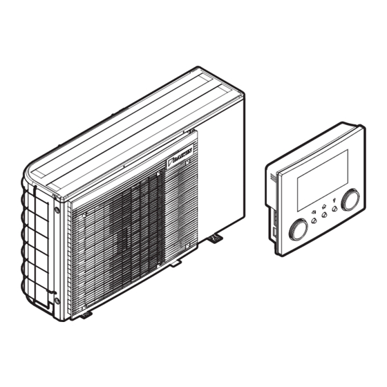
About the box 4 About the box Keep the following in mind: ▪ At delivery, the unit MUST be checked for damage and completeness. Any damage or missing parts MUST be reported immediately to the claims agent of the carrier. ▪... - Page 19 About the box 1× 1× 1× 1× 1× 1× 1× 2× 4× 3× 4× 8× 4× 8× a Installation manual vibration dampers b General safety precautions c Operation manual d Installation manual e Addendum book for optional equipment f Energy label g User interface (front plate, rear plate, screws, and wall plugs) h Unit mounting plate i Vibration dampers...
-
Page 20: About The Units And Options
About the units and options 5 About the units and options In this chapter Identification................................... 5.1.1 Identification label: Outdoor unit .......................... Combining units and options..............................5.2.1 Possible options for the outdoor unit........................5.1 Identification 5.1.1 Identification label: Outdoor unit Location Model identification Example: EW Y A 006 D2 V3 P -H Code... -
Page 21: Combining Units And Options
About the units and options 5.2 Combining units and options INFORMATION Certain options may NOT be available in your country. 5.2.1 Possible options for the outdoor unit Room thermostat (EKRTWA, EKRTRB) You can connect an optional room thermostat to the outdoor unit. This thermostat can either be wired (EKRTWA) or wireless (EKRTRB). - Page 22 About the units and options Remote outdoor sensor (EKRSCA1) By default the sensor inside the outdoor unit will be used to measure the outdoor temperature. As an option the remote outdoor sensor can be installed to measure the outdoor temperature on another location (e.g. to avoid direct sunlight) to have an improved system behaviour.
- Page 23 About the units and options For installation instructions, see the installation and operation manual of the Human Comfort Interface (HCI) as room thermostat, and the addendum book for optional equipment. Domestic hot water tank thermistor (EKTESE1, EKTESE2) To increase the maximum distance between the domestic hot water tank and the outdoor unit, a 30 m thermistor can be connected.
-
Page 24: Application Guidelines
Application guidelines 6 Application guidelines INFORMATION Heating is only applicable in case of reversible models. In this chapter Overview: Application guidelines ............................Setting up the space heating/cooling system ........................6.2.1 Single room................................6.2.2 Multiple rooms – One LWT zone ........................... 6.2.3 Multiple rooms –... -
Page 25: Setting Up The Space Heating/Cooling System
Application guidelines NOTICE Certain types of fan coil units are able to receive input of the outdoor unit operation mode (cooling or heating X2M/3 and X2M/4) and/or to send output of the fan coil unit thermostatic condition (main zone: X2M/30 and X2M/35; additional zone: X2M/30 and X2M/35a). -
Page 26: Single Room
Application guidelines 6.2.1 Single room Underfloor heating or radiators – Wired room thermostat Setup A Main leaving water temperature zone B One single room a User interface (delivered as accessory) b Dedicated Human Comfort Interface (BRC1HHDA used as room thermostat) ▪... - Page 27 ▪ Code: [C-05] demand. Benefits ▪ Wireless. The Daikin external room thermostat is available in a wireless version. ▪ Efficiency. Although the external room thermostat only sends ON/OFF signals, it is specifically designed for the heat pump system. ▪ Comfort. In case of underfloor heating, the wireless external room thermostat prevents condensation on the floor during cooling operation by measuring the room humidity.
- Page 28 Application guidelines Fan coil units Setup A Main leaving water temperature zone B One single room a User interface (delivered as accessory) b Remote controller of the fan coil units ▪ For more information about connecting the electrical wiring to the unit, see "9.2 Connections to the outdoor unit" [ 76].
- Page 29 Application guidelines ▪ Stylish. Combination: Underfloor heating + Fan coil units ▪ Space heating is provided by: The underfloor heating The fan coil units ▪ Space cooling is provided by the fan coil units only. The underfloor heating is shut off by the shut-off valve.
-
Page 30: Multiple Rooms - One Lwt Zone
Application guidelines Setting Value External room thermostat for the main 1 (1 contact): When the used zone: external room thermostat or fan coil unit can only send a thermo ON/OFF ▪ #: [2.A] condition. No separation between ▪ Code: [C-05] heating or cooling demand. - Page 31 Application guidelines ▪ The room temperature of the main room is controlled by the dedicated Human Comfort Interface (BRC1HHDA used as room thermostat). ▪ A thermostatic valve is installed before the underfloor heating in each of the other rooms. INFORMATION Mind situations where the main room can be heated by another heating source.
- Page 32 Application guidelines Configuration Setting Value Unit temperature control: 1 (External room thermostat): Unit operation is decided by the ▪ #: [2.9] external thermostat. ▪ Code: [C-07] Number of water temperature zones: 0 (Single zone): Main ▪ #: [4.4] ▪ Code: [7-02] Benefits Compared with fan coil units for one room: ▪...
-
Page 33: Multiple Rooms - Two Lwt Zones
Application guidelines ▪ The user interface connected to the outdoor unit decides the space operation mode. Mind that the operation mode on each external room thermostat and remote controller of the fan coil units must be set to match the outdoor unit. Configuration Setting Value... - Page 34 Application guidelines System with hydraulic separator for main zone: System with hydraulic separator for both zones: For this system, a direct pump is required for the additional zone. A Additional leaving water temperature zone B Room 1 C Room 2 D Main leaving water temperature zone E Room 3 a Heat pump convectors (+ controllers)
- Page 35 Application guidelines b Dedicated Human Comfort Interface (BRC1HHDA used as room thermostat) c Mixing valve station d Pressure regulating valve (field supply) e Safety thermostat (field supply) f Bizone kit control box (EKMIKPOA) g Bypass valve h Hydraulic separator (balancing bottle) i Direct pump (for additional zone) (e.g.
-
Page 36: Setting Up An Auxiliary Heat Source For Space Heating
Application guidelines Setting Value In case of heat pump convectors: 1 (1 contact): When the used external room thermostat or heat pump External room thermostat for the convector can only send a thermo ON/ additional zone: OFF condition. No separation between ▪ #: [3.A] heating or cooling demand. - Page 37 ▪ Make sure the auxiliary boiler and its integration in the system complies with applicable legislation. ▪ Daikin is NOT responsible for incorrect or unsafe situations in the auxiliary boiler system. EWAA004~008D + EWYA004~008D Installer reference guide Packaged air-cooled water chillers and packaged air to water heat pumps 4P688013-1B –...
- Page 38 Application guidelines ▪ Make sure the return water to the heat pump does NOT exceed 60°C. To do so: Set the desired water temperature via the auxiliary boiler controller to maximum 60°C. Install an aquastat valve in the return water flow of the heat pump. Set the aquastat valve to close above 60°C and to open below 60°C.
-
Page 39: Setting Up The Energy Metering
Application guidelines H Heating demand room thermostat (optional) K1A Auxiliary relay for activation of outdoor unit (field supply) K2A Auxiliary relay for activation of boiler (field supply) Outdoor Outdoor unit Auto Automatic Boiler Boiler Setpoint of the auxiliary gas boiler To prevent freeze-up of the water piping, the auxiliary gas boiler must have a fixed setpoint ≥55°C, or a weather-dependent setpoint ≥T (°C) -
Page 40: Consumed Energy
Application guidelines ▪ The produced heat is calculated internally based on: The leaving and entering water temperature The flow rate ▪ Setup and configuration: No additional equipment needed. 6.4.2 Consumed energy You can use the following methods to determine the consumed energy: ▪... - Page 41 Application guidelines Power meter Description Measures: Entire system Connection: X5M/5+6 Power meter type: ▪ Three-phase power meter in case one of the following conditions is met: Power supply of the external backup heater kit (if any) is ▪ Single-phase power meter in other cases. 2 power meters.
- Page 42 Application guidelines * 3N~ A Outdoor unit B External backup heater kit a Electrical cabinet: Normal kWh rate power supply b Power meter c Overcurrent fuse d Compressor module e Hydro module f Backup heater Examples in case of preferential kWh rate power supply WITHOUT separate normal kWh rate power supply 1 power meter is sufficient.
-
Page 43: Setting Up The Power Consumption Control
Application guidelines A Outdoor unit B External backup heater kit a1 Electrical cabinet: Normal kWh rate power supply a2 Electrical cabinet: Preferential kWh rate power supply b1 Power meter 1 b2 Power meter 2 c Overcurrent fuse d Compressor module e Hydro module f Backup heater S1S Preferential kWh rate power supply contact... -
Page 44: Permanent Power Limitation
6.5.2 Power limitation activated by digital inputs Power limitation is also useful in combination with an energy management system. The power or current of the entire Daikin system is limited dynamically by digital inputs (maximum four steps). Each power limitation level is set via the user interface by limiting one of the following: ▪... -
Page 45: Power Limitation Process
Application guidelines Power input t Time DI Digital inputs (power limitation levels) a Power limitation active b Actual power input Setup ▪ Demand PCB (option EKRP1AHTA) needed. ▪ Maximum four digital inputs are used to activate the corresponding power limitation level: DI1 = strongest limitation (lowest energy consumption) DI4 = weakest limitation (highest energy consumption) ▪... -
Page 46: Bbr16 Power Limitation
Application guidelines Produced heat Consumed energy A Outdoor unit B Backup heater a Limited outdoor unit operation b Full outdoor unit operation c Backup heater step 1 turned ON d Backup heater step 2 turned ON 6.5.4 BBR16 power limitation INFORMATION Restriction: BBR16 settings are only visible when the language of the user interface is set to Swedish. -
Page 47: Setting Up An External Temperature Sensor
Application guidelines 6.6 Setting up an external temperature sensor You can connect one external temperature sensor. It measures the indoor or outdoor ambient temperature. We recommend to use an external temperature sensor in the following cases: Indoor ambient temperature ▪ In room thermostat control, the dedicated Human Comfort Interface (BRC1HHDA used as room thermostat) measures the indoor ambient temperature. -
Page 48: Unit Installation
Unit installation 7 Unit installation In this chapter Preparing the installation site ..............................7.1.1 Installation site requirements of the outdoor unit ....................7.1.2 Additional installation site requirements of the outdoor unit in cold climates ........... Mounting the outdoor unit ..............................7.2.1 About mounting the outdoor unit ......................... - Page 49 Unit installation a Air outlet b Air inlet NOTICE ▪ Do NOT stack the units on each other. ▪ Do NOT hang the unit on a ceiling. Strong winds (≥18 km/h) blowing against the outdoor unit’s air outlet causes short circuit (suction of discharge air). This may result in: ▪...
-
Page 50: Additional Installation Site Requirements Of The Outdoor Unit In Cold Climates
Unit installation Seaside installation. Make sure the outdoor unit is NOT directly exposed to sea winds. This is to prevent corrosion caused by high levels of salt in the air, which might shorten the life of the unit. Install the outdoor unit away from direct sea winds. Example: Behind the building. -
Page 51: Mounting The Outdoor Unit
Unit installation 4× a Suction grille Protect the outdoor unit against direct snowfall and take care that the outdoor unit is NEVER snowed up. a Snow cover or shed b Pedestal c Prevailing wind direction d Air outlet In any case, provide at least 300 mm of free space below the unit. Additionally, make sure the unit is positioned at least 100 ... -
Page 52: Precautions When Mounting The Outdoor Unit
Unit installation Typical workflow Mounting the outdoor unit typically consists of the following stages: Providing the installation structure. Installing the outdoor unit. Providing drainage. Preventing the unit from falling over. Protecting the unit against snow and wind by installing a snow cover and baffle plates. -
Page 53: To Install The Outdoor Unit
Unit installation Option 2: On plastic mounting feet In this case, you can use the bolts, nuts, washers and spring washers delivered with the unit as accessories. 0 mm 7.2.4 To install the outdoor unit CAUTION To avoid injury, do NOT touch the air inlet or aluminium fins of the unit. CAUTION Do NOT remove the protective cardboard before the unit is installed properly. -
Page 54: To Provide Drainage
Unit installation ▪ Keep both sides of the sling level. ▪ Keep your back straight. ±110 3 Install the outdoor unit as follows: ▪ (1) Put the unit into position. ▪ (2) Remove the slings (by pulling 1 side of the sling). ▪... -
Page 55: To Prevent The Outdoor Unit From Falling Over
Unit installation ▪ Install the unit on a base to make sure that there is proper drainage in order to avoid ice accumulation. ▪ Prepare a water drainage channel around the foundation to drain waste water away from the unit. ▪... -
Page 56: Opening And Closing The Unit
Unit installation 7.3 Opening and closing the unit 7.3.1 About opening the units At certain times, you have to open the unit. Example: ▪ When connecting the electrical wiring ▪ When maintaining or servicing the unit DANGER: RISK OF ELECTROCUTION Do NOT leave the unit unattended when the service cover is removed. -
Page 57: To Rotate The Switch Box
Unit installation 7.3.3 To rotate the switch box During the installation, you will need access to the inside of the outdoor unit. To have easier front access, rotate the switch box out of the unit as follows: Prerequisite: The front plate has been removed. 1 Push down the clip of the switch box holder. - Page 58 Unit installation 3.55 N . m 5× a Speed nut EWAA004~008D + EWYA004~008D Installer reference guide Packaged air-cooled water chillers and packaged air to water heat pumps 4P688013-1B – 2022.09...
-
Page 59: Piping Installation
Piping installation 8 Piping installation In this chapter Preparing water piping ................................8.1.1 Water circuit requirements ........................... 8.1.2 Formula to calculate the expansion vessel pre-pressure..................8.1.3 To check the water volume and flow rate......................8.1.4 Changing the pre-pressure of the expansion vessel ..................... 8.1.5 To check the water volume: Examples ........................ - Page 60 For the external static pressure curves of the outdoor unit, see the technical data. A subset of the latest technical data is available on the regional Daikin website (publicly accessible). The full set of latest technical data is available on the Daikin Business Portal (authentication required).
-
Page 61: Formula To Calculate The Expansion Vessel Pre-Pressure
Piping installation ▪ Air vents. Provide air vents at all high points of the system, which must also be easily accessible for servicing. The outdoor unit has an automatic air purge valve. The external backup heater kit (option) has an automatic air purge valve. Check that the automatic air purge valves are NOT tightened too much, so that the automatic release of air from the water circuit is possible. - Page 62 Piping installation If… Then the minimum water volume is… Connected 15 l NOT connected and… The return flow temperature is >15°C 20 l The return flow temperature is ≤15°C 50 l INFORMATION In critical processes, or in rooms with a high heat load, extra water might be required.
- Page 63 Piping installation A Pre-pressure (bar) B Maximum water volume (l) Water Water + glycol Example: Maximum water volume and expansion vessel pre-pressure Installation Water volume height ≤185/105 l >185/105 l difference ≤7 m No pre-pressure adjustment is Do the following: required. ▪ Decrease the pre-pressure according to the required installation height...
-
Page 64: Changing The Pre-Pressure Of The Expansion Vessel
Piping installation If operation is… Then the minimum required flow rate is… BUH operation 12 l/min Heating defrost 12 l/min NOTICE If glycol was added to the water circuit, and the temperature of the water circuit is low, the flow rate will NOT be displayed on the user interface. In this case, the minimum flow rate can be checked by way of the pump test. -
Page 65: Connecting Water Piping
Piping installation No actions or adjustments are required. Example 2 The outdoor unit is installed at the highest point in the water circuit. The total water volume in the water circuit is 250 l. Actions: ▪ Because the total water volume (250 l) is more than the default water volume (185 l), the pre-pressure must be decreased. -
Page 66: To Connect The Water Piping
Piping installation 8.2.3 To connect the water piping NOTICE Do NOT use excessive force when connecting the field piping and make sure the piping is aligned properly. Deformation of the piping can cause malfunctioning of the unit. NOTICE When connecting the field piping, hold the nut on the inside of the unit in place using a spanner to provide extra leverage. -
Page 67: To Protect The Water Circuit Against Freezing
Piping installation NOTICE For service purposes, it is recommended to also install a shut-off valve and drain point to the water OUT connection. This shut-off valve and drain point are field supplied. NOTICE Install air purge valves at all local high points. 8.2.4 To protect the water circuit against freezing About freeze protection Frost can damage the system. - Page 68 Piping installation WARNING Due to the presence of glycol, corrosion of the system is possible. Uninhibited glycol will turn acidic under the influence of oxygen. This process is accelerated by the presence of copper and high temperatures. The acidic uninhibited glycol attacks metal surfaces and forms galvanic corrosion cells that cause severe damage to the system.
- Page 69 Piping installation NOTICE ▪ The required concentration might differ depending on the type of glycol. ALWAYS compare the requirements from the table above with the specifications provided by the glycol manufacturer. If necessary, meet the requirements set by the glycol manufacturer.
-
Page 70: To Fill The Water Circuit
Piping installation Part Description Protection for the field piping. ▪ Install the freeze protection valves: At all lowest points of the field piping. In the coldest part of the field piping, away from heat sources. Vertically to allow water to flow out properly. >15 ... -
Page 71: To Insulate The Water Piping
Hydronic Piping Calculation tool. The Hydronic Piping Calculation tool is part of the Heating Solutions Navigator which can be reached via https://professional.standbyme.daikin.eu. Please contact your dealer if you have no access to Heating Solutions Navigator. This recommendation ensures good operation of the unit, however, local regulations may differ and shall be followed. -
Page 72: Electrical Installation
Electrical installation 9 Electrical installation In this chapter About connecting the electrical wiring ..........................9.1.1 Precautions when connecting the electrical wiring ....................9.1.2 Guidelines when connecting the electrical wiring ....................9.1.3 About electrical compliance ..........................9.1.4 About preferential kWh rate power supply......................9.1.5 Overview of electrical connections except external actuators................ -
Page 73: Guidelines When Connecting The Electrical Wiring
Electrical installation WARNING ▪ If the power supply has a missing or wrong N-phase, equipment might break down. ▪ Establish proper earthing. Do NOT earth the unit to a utility pipe, surge absorber, or telephone earth. Incomplete earthing may cause electrical shock. ▪... -
Page 74: About Electrical Compliance
Electrical installation Wire type Installation method Stranded conductor wire with round crimp-style terminal a Terminal b Screw c Flat washer Allowed NOT allowed Tightening torques Item Tightening torque (N•m) 2.45 ±10% 0.88 ±10% 0.88 ±10% 2.45 ±10% 0.88 ±10% 0.88 ±10% 2.45 ±10% X10M 0.88 ±10%... -
Page 75: Overview Of Electrical Connections Except External Actuators
Electrical installation The hydro module of the outdoor unit is designed to receive an input signal by which the unit switches into forced off mode. At that moment, the outdoor unit compressor will not operate. The wiring to the unit is different depending on whether the power supply is interrupted or NOT. -
Page 76: Connections To The Outdoor Unit
Electrical installation S1S Preferential kWh rate power supply contact Preferential kWh rate power supply WITH separate normal kWh rate power supply During preferential kWh rate power supply activation, power supply is interrupted immediately or after some time by the electricity company. In this case, the hydro module of the outdoor unit must be powered by a separate normal kWh rate power supply. - Page 77 Electrical installation Item Description Room thermostat (wired or In case of wireless room thermostat, see: wireless) ▪ Installation manual of the wireless room thermostat ▪ Addendum book for optional equipment In case of wired room thermostat, see: ▪ Installation manual of the wired room thermostat ▪...
-
Page 78: To Connect The Electrical Wiring To The Outdoor Unit
Electrical installation Item Description WLAN cartridge See: ▪ Installation manual of the WLAN cartridge ▪ Installer reference guide — [D] Wireless gateway Flow switch See installation manual of the flow switch Wires: 2×0.5 mm² — Location extra components The following illustration shows the location of the extra components that you need to install on the outdoor unit when using certain option kits. -
Page 79: To Connect The Main Power Supply
Electrical installation a High voltage options b Low voltage options c Power supply for backup heater (in case of unit with integrated backup heater) Wiring for backup heater kit (in case of external backup heater kit) d Unit power supply 4 Connect the wires to the appropriate terminals, and fix the cables with cable ties. - Page 80 Electrical installation In case of preferential kWh rate power supply Preferential kWh rate Wires: 1N+GND power supply Maximum running current: Refer to name plate on unit. Separate normal kWh Wires: 1N rate power supply Maximum running current: 6.3 A Preferential kWh rate Wires: 2×(0.75~1.25 mm²) power supply contact Maximum length: 50 m.
- Page 81 Electrical installation 1N~, 50 Hz, 230 V AC, 6.3 A 180° 3 Connect the preferential power supply contact. X5M.10 X5M.9 180° 9 10 4 In case of a separate normal kWh rate power supply, disconnect X11Y from X11YA, and connect X11Y to X11YB. EWAA004~008D + EWYA004~008D Installer reference guide Packaged air-cooled water chillers...
-
Page 82: External Backup Heater Kit
Electrical installation X19A X11YB X11Y X11YA X19A X11YA X11Y X11YB 5 Fix the cables with cable ties to the cable tie mountings. 9.2.3 External backup heater kit For reversible models, you can install the external backup heater kit (EKLBUHCB6W1). If you do so, then under certain conditions you also need to install a bypass valve kit (EKMBHBP1). - Page 83 Electrical installation Depending on the configuration (wiring on X14M, and settings in [9.3] Backup heater), the backup heater capacity can vary. Make sure that the power supply is in accordance with the backup heater capacity, as listed in the table below. Backup heater Backup Power supply...
- Page 84 Electrical installation Capacity – Power X14M supply X14M 6 kW 3N~ 400 V 1 2 3 4 5 6 9 kW 3N~ 400 V L1 L2 Q3DI 3N~ , 50 Hz 400 V AC 3 Fix the cable with cable ties to the cable tie mountings. During connection of the backup heater, miswiring is possible.
- Page 85 Electrical installation To connect the backup heater kit to the outdoor unit The wiring between the backup heater kit and the outdoor unit is as follows: X15M 9 10 X15M EKLBUHCB6W A Outdoor unit B Backup heater kit HV High voltage connections (backup heater thermal protector + backup heater connection) LV Low voltage connection (backup heater thermistor) NOTICE...
- Page 86 Electrical installation 180° 1 2 3 4 5 3 On the outdoor unit, connect the LV cable to the appropriate terminals as shown in the illustration below. X15M EKLBUHCB6W 180° 4 Fix the cables with cable ties to the cable tie mountings. Bypass valve kit necessity For reversible systems (heating+cooling) in which an external backup heater kit is installed, the installation of valve kit EKMBHBP1 is required if condensation is...
- Page 87 Electrical installation B (°C DB) A Leaving water evaporator temperature B Dry-bulb temperature Relative humidity 40% Relative humidity 60% Relative humidity 80% Example: Given are an ambient temperature of 25°C and a relative humidity of 40%. If the leaving water evaporator temperature is <12°C, condensation will occur.
-
Page 88: To Connect The User Interface
Electrical installation EKMBHBP1 FHL1 FHL2 FHL3 Alpex 18°C 0.25 m 0.1 m 5°C 0.5 m 0.2 m 2 On the outdoor unit, connect B to the appropriate terminals as shown in the illustration below. X2M.4 X2M.3 X2M.14a 180° 3 Fix the cable with cable ties to the cable tie mountings. 9.2.4 To connect the user interface This topic describes the following: ▪... - Page 89 Electrical installation Connecting the user interface cable to the outdoor unit Wires: 4×(0.75~1.25 mm²) Maximum length: 200 m [2.9] Control [1.6] Room sensor offset 1 Connect the user interface cable to the outdoor unit. Fix the cable with cable ties to the cable tie mountings. X5M.11 X5M.12 P1P2...
- Page 90 Electrical installation a Front plate b Rear plate c Screws d Wall plugs 1 Mount the rear plate to the wall. ▪ Use the 2 screws and wall plugs. ▪ Use any of the 6 holes. The holes are compatible with standard electrical box extenders of 60 mm.
-
Page 91: To Connect The Shut-Off Valve
Electrical installation a Positioning pins b Connector pins Opening the user interface after it is installed If you need to open the user interface after it is installed, proceed as follows: 1 Remove the WLAN cartridge and USB memory stick (if any). 2 Push the rear plate on each of the 4 spots where the snap-fits are located. -
Page 92: To Connect The Electricity Meters
Electrical installation NOTICE Only connect NO (normally open) valves. X2M.3 X2M.4 (NO) 180° 3 Fix the cable with cable ties to the cable tie mountings. 9.2.6 To connect the electricity meters Wires: 2 (per meter)×0.75 mm² Electricity meters: 12 V DC pulse detection (voltage supplied by PCB) [9.A] Energy metering INFORMATION In case of an electricity meter with transistor output, check the polarity. -
Page 93: To Connect The Alarm Output
Electrical installation 180° 3 4 5 6 3 Fix the cable with cable ties to the cable tie mountings. 9.2.7 To connect the alarm output Wires: (2+1)×0.75 mm² Maximum load: 0.3 A, 250 V AC [9.D] Alarm output 1 Open the service cover. See "7.3.2 To open the outdoor unit" [ 56]. -
Page 94: To Connect The Space Cooling/Heating On/Off Output
Electrical installation 180° YC Y1 X2M.9 YC Y1 a Installation of EKRP1HBAA is required. WARNING Stripped wire. Make sure that stripped wire cannot make contact with possible water on the bottom plate. 3 Fix the cable with cable ties to the cable tie mountings. 9.2.8 To connect the space cooling/heating ON/OFF output INFORMATION Heating is only applicable in case of reversible models. -
Page 95: To Connect The Changeover To External Heat Source
Electrical installation 180° X2M.9 YC Y2 a Installation of EKRP1HBAA is required. WARNING Stripped wire. Make sure that stripped wire cannot make contact with possible water on the bottom plate. 3 Fix the cable with cable ties to the cable tie mountings. 9.2.9 To connect the changeover to external heat source INFORMATION Bivalent is only possible in case of 1 leaving water temperature zone with:... -
Page 96: To Connect The Power Consumption Digital Inputs
Electrical installation 180° a Installation of EKRP1HBAA is required. 3 Fix the cable with cable ties to the cable tie mountings. 9.2.10 To connect the power consumption digital inputs Wires: 2 (per input signal)×0.75 mm² Power limitation digital inputs: 12 V DC / 12 mA detection (voltage supplied by PCB) [9.9] Power consumption control. -
Page 97: To Connect The Safety Thermostat (Normally Closed Contact)
Electrical installation 9.2.11 To connect the safety thermostat (normally closed contact) Wires: 2×0.75 mm² Maximum length: 50 m Safety thermostat contact: 16 V DC detection (voltage supplied by PCB). The voltage-free contact shall ensure the minimum applicable load of 15 V DC, 10 mA. — 1 Open the service cover. See "7.3.2 To open the outdoor unit" [ 56]. - Page 98 Electrical installation ▪ In case of high voltage Smart Grid contacts. This requires the installation of the Smart Grid relay kit (EKRELSG). The 2 incoming Smart Grid contacts can activate the following Smart Grid modes: Smart Grid contact Smart Grid operation mode Free running Forced off Recommended on...
- Page 99 Electrical installation 180° 3 4 5 6 9 10 13 14 2 Fix the cables with cable ties to the cable tie mountings. In case of high voltage Smart Grid contacts Wires (Smart Grid pulse meter): 0.5 mm² Wires (high voltage Smart Grid contacts): 1 mm² [9.8.4]=3 (Benefit kWh power supply = Smart grid) [9.8.5] Smart grid operation mode [9.8.6] Allow electrical heaters...
- Page 100 Electrical installation K1A Relay for Smart Grid contact 1 K2A Relay for Smart Grid contact 2 X10M Terminal block a Screws for X10M b Screws for K1A and K2A c Sticker to put on the high voltage wires d Wires between the relays and X5M (AWG22 ORG) e Wires between the relays and X10M (AWG18 RED) 5 6 9 10 1 2 3 4...
-
Page 101: To Connect The Wlan Cartridge (Delivered As Accessory)
Electrical installation 180° X10M 1 2 3 4 4 Fix the cables with cable ties to the cable tie mountings. If necessary, bundle excessive cable length with a cable tie. 9.2.13 To connect the WLAN cartridge (delivered as accessory) [D] Wireless gateway 1 Insert the WLAN cartridge into the cartridge slot on the user interface of the indoor unit. -
Page 102: Finishing The Outdoor Unit Installation
Finishing the outdoor unit installation 10 Finishing the outdoor unit installation 10.1 To check the insulation resistance of the compressor NOTICE If, after installation, refrigerant accumulates in the compressor, the insulation resistance over the poles can drop, but if it is at least 1 MΩ, then the unit will not break down. -
Page 103: Configuration
Configuration 11 Configuration INFORMATION Heating is only applicable in case of reversible models. In this chapter 11.1 Overview: Configuration................................. 103 11.1.1 To access the most used commands ........................104 11.1.2 To connect the PC cable to the switch box ......................106 11.2 Configuration wizard ................................ -
Page 104: To Access The Most Used Commands
Configuration ▪ First time – Configuration wizard. When you turn ON the user interface for the first time (via the unit), the configuration wizard starts to help you configure the system. ▪ Restart the configuration wizard. If the system is already configured, you can restart the configuration wizard. - Page 105 Configuration Installer 5678 Advanced user pin code The Advanced user pin code is 1234. Additional menu items for the user are now visible. Advanced user 1234 User pin code The User pin code is 0000. User 0000 To access the installer settings 1 Set the user permission level to Installer.
-
Page 106: To Connect The Pc Cable To The Switch Box
Configuration 5 Turn the right dial to modify the value from 15 to 20. 01 20 6 Press the left dial to confirm the new setting. 7 Press the center button to go back to the home screen. INFORMATION When you change the overview settings and you go back to the home screen, the user interface will show a popup screen and request to restart the system. -
Page 107: Configuration Wizard
Configuration 11.2 Configuration wizard After first power ON of the system, the user interface starts a configuration wizard. Use this wizard to set the most important initial settings for the unit to run properly. If required, you can afterwards configure more settings. You can change all these settings via the menu structure. -
Page 108: Possible Screens
Configuration For the setting… Refer to… Emitter type [2.7] "11.6.3 Main zone" [ 133] Control [2.9] Setpoint mode [2.4] Heating WD curve [2.5] (if applicable) Cooling WD curve [2.6] (if applicable) Schedule [2.1] WD curve type [2.E] Additional zone (only if [4.4]=1) Emitter type [3.7] "11.6.4 Additional zone" [... -
Page 109: Home Screen
Configuration – a Home screen b Main menu screen c Lower level screens: c1: Setpoint screen c2: Detailed screen with values c3: Screen with weather-dependent curve c4: Screen with schedule 11.3.2 Home screen Press the button to go back to the home screen. You see an overview of the unit configuration and the room and setpoint temperatures. - Page 110 Configuration Item Description Emergency Heat pump failure and system operates in Emergency mode or heat pump is forced off. Current date and time Smart energy Smart energy is available via solar panels or smart grid. Smart energy is currently being used for space heating. Space operation mode Cooling Heating...
-
Page 111: Main Menu Screen
Configuration Item Description Additional zone h1 Installed room thermostat type: Unit operation is decided by the external room thermostat (wired or wireless). — No room thermostat installed or set. Unit operation is decided based on the leaving water temperature regardless of the actual room temperature and/or heating demand of the room. -
Page 112: Menu Screen
Configuration Submenu Description Restriction: Only displayed if a dedicated Room Human Comfort Interface (BRC1HHDA used as room thermostat) is controlling the outdoor unit. Set the room temperature. Main zone Shows the applicable symbol for your main zone emitter type. Set the leaving water temperature for the main zone. -
Page 113: Setpoint Screen
Configuration Possible actions on this screen Enter the submenu/setting. 11.3.5 Setpoint screen The setpoint screen is displayed for screens describing system components that need a setpoint value. Examples [1] Room temperature screen [2] Main zone screen °C °C – – Room Main zone [3] Additional zone screen... -
Page 114: Detailed Screen With Values
Configuration 11.3.6 Detailed screen with values Example: 7.2.1 Time/date Hours Minutes a Settings b Values c Selected setting and value Possible actions on this screen Go through the list of settings. Change the value. Go to the next setting. Confirm changes and proceed. 11.4 Preset values and schedules 11.4.1 Using preset values About preset values... -
Page 115: Using And Programming Schedules
Configuration 11.4.2 Using and programming schedules About schedules Depending on your system layout and installer configuration, schedules for multiple controls may be available. You can… See… Set if a specific control needs to act according "Activation screen" in "Possible to a schedule. schedules" [ 115] Select which schedule you currently want to use for a specific control. - Page 116 Configuration ▪ Activation screen: For most controls, a schedule is only effective if it activated in its corresponding activation screen. This entry shows you where to activate it. ▪ Possible actions: Actions you can use when programming a schedule. For most schedules, you can program up to 6 actions per day.
-
Page 117: Schedule Screen: Example
Configuration Schedule/Control Description [4.2] Space heating/ "To set the space operation mode" [ 147]. cooling > Operation mode schedule Schedule (per month) for when to operate the unit in heating mode and when in cooling mode. [7.4.2] User settings > Predefined schedules: 1 Quiet >... - Page 118 Configuration 2 (optional) Clear the content of the whole week schedule or the content of a selected day schedule. 3 Program the schedule for Monday. 4 Copy the schedule to the other weekdays. 5 Program the schedule for Saturday and copy it to Sunday. 6 Give the schedule a name.
- Page 119 Configuration To program the schedule for Monday 1 Select Monday. User defined 1 2 Select Edit. Delete Edit Copy 3 Use the left dial to select an entry and edit the entry with the right dial. You can program up to 6 actions each day. On the bar, a high temperature has a darker colour than a low temperature.
- Page 120 Configuration 3 Select Tuesday. User defined 1 4 Select Paste. Delete Edit Copy Paste Result: User defined 1 5 Repeat this action for all other weekdays. — User defined 1 To program the schedule for Saturday and copy it to Sunday 1 Select Saturday.
-
Page 121: Setting The Energy Prices
Configuration To rename the schedule 1 Select the name of the current schedule. User defined 1 2 Select Rename. Delete Rename Select 3 (optional) To delete the current schedule name, browse through the character list until ← is displayed, then press to remove the previous character. - Page 122 Configuration INFORMATION Price value ranging from 0.00~990 valuta/kWh (with 2 significant values). To set the electricity price 1 Go to [7.5.1]/[7.5.2]/[7.5.3]: User settings > Electricity price > High/Medium/Low. 2 Select the correct electricity price. 3 Confirm the changes. 4 Repeat this for all three electricity prices. —...
-
Page 123: Weather-Dependent Curve
Configuration For the procedure to set the electricity price, see "To set the electricity price" [ 122]. Example This is an example and the prices and/or values used in this example are NOT accurate. Data Price/kWh Gas price 4.08 Electricity price 12.49 Renewable heat incentive per kWh Calculation of the gas price... -
Page 124: 2-Points Curve
Configuration ▪ 2-points curve ▪ Slope-offset curve Which type of curve you use to make adjustments, depends on your personal preference. See "11.5.4 Using weather-dependent curves" [ 126]. Availability The weather-dependent curve is available for: ▪ Main zone - Heating ▪ Main zone - Cooling ▪... -
Page 125: Slope-Offset Curve
Configuration 11.5.3 Slope-offset curve Slope and offset Define the weather-dependent curve by its slope and offset: ▪ Change the slope to differently increase or decrease the temperature of the leaving water for different ambient temperatures. For example, if leaving water temperature is in general fine but at low ambient temperatures too cold, raise the slope so that leaving water temperature is heated increasingly more at decreasingly lower ambient temperatures. -
Page 126: Using Weather-Dependent Curves
Configuration Item Description Y1, Y2, Y3, Examples of desired leaving water temperature. The icon corresponds to the heat emitter for that zone: ▪ : Underfloor heating ▪ : Fan coil unit ▪ : Radiator Possible actions on this screen Select slope or offset. Increase or decrease the slope/offset. - Page 127 Configuration Zone Go to … Additional zone – Heating [3.5] Additional zone > Heating WD curve Additional zone – Cooling [3.6] Additional zone > Cooling WD curve INFORMATION Maximum and minimum setpoints You cannot configure the curve with temperatures that are higher or lower than the set maximum and minimum setpoints for that zone.
-
Page 128: Settings Menu
Configuration 11.6 Settings menu You can set additional settings using the main menu screen and its submenus. The most important settings are presented here. 11.6.1 Malfunctioning In case of a malfunction, will appear on the home screen. To display the error code, open the menu screen and go to [0] ... - Page 129 Configuration "11.4.3 Schedule screen: Example" [ 117]. Cooling schedule Applicable for all models. Define a cooling schedule of the room temperature in [1.3] Cooling schedule. "11.4.3 Schedule screen: Example" [ 117]. Antifrost [1.4] Antifrost prevents the room from getting too cold. This setting is applicable when [2.9] Control=Room thermostat, but also offers functionality for leaving water temperature control and external room thermostat control.
- Page 130 Configuration NOTICE If the room Antifrost setting is active and a U4 error occurs, the unit will automatically start the Antifrost function via the backup heater. If the backup heater is not allowed for room frost protection during a U4 error, the room Antifrost setting MUST be disabled.
- Page 131 Configuration If... Then... ▪ Space heating/cooling=On, and ▪ The unit will supply leaving water to the heat emitters to heat up the room ▪ The external room thermostat is again, and "Thermo OFF", and ▪ the temperature setpoint of the ▪...
- Page 132 Configuration NOTICE If Emergency is set to Manual ([9.5.1]=0), and the unit is triggered to start emergency operation, the unit will stop and needs to be recovered manually via the user interface. To recover operation manually, go to the Malfunctioning main menu screen, and confirm emergency operation before starting.
-
Page 133: Main Zone
Configuration If room buffering is enabled, the extra energy from photovoltaic panels is buffered in the DHW tank and in the space heating/cooling circuit (i.e. heat up or cool down the room). With the room comfort setpoints (cooling/heating) you can modify the maximum/minimum setpoints that will be used when buffering the extra energy in the space heating/cooling circuit. - Page 134 Configuration Code Description [2.1] Schedule: ▪ 0: No ▪ 1: Yes Heating schedule Define a heating temperature schedule for the main zone via [2.2] Heating schedule. "11.4.3 Schedule screen: Example" [ 117]. Cooling schedule Define a cooling temperature schedule for the main zone via [2.3] Cooling schedule.
- Page 135 Configuration Code Description [2.5] [1-00] Set weather-dependent heating: [1-01] Note: There are 2 methods to set the weather dependent curve. See "11.5.2 2-points [1-02] curve" [ 124] and "11.5.3 Slope-offset [1-03] curve" [ 125]. Both curve types require 4 field settings to be configured according to the figure below.
- Page 136 Configuration Code Description [2.6] [1-06] Set weather-dependent cooling: [1-07] Note: There are 2 methods to set the weather dependent curve. See "11.5.2 2-points [1-08] curve" [ 124] and "11.5.3 Slope-offset [1-09] curve" [ 125]. Both curve types require 4 field settings to be configured according to the figure below.
- Page 137 Configuration Code Description [2.7] [2‑0C] Emitter type: ▪ 0: Underfloor heating ▪ 1: Fancoil unit ▪ 2: Radiator The setting Emitter type influences the space heating setpoint range and the target delta T in heating as follows: Emitter type Main Space heating setpoint Target delta T in heating zone...
- Page 138 Configuration Setpoint range To prevent a wrong (i.e. too hot or too cold) leaving water temperature for the main leaving water temperature zone, limit its temperature range. NOTICE In case of a floor heating application it is important to limit the: ▪...
- Page 139 Configuration Control Define how the operation of the unit is controlled. Control In this control... Leaving water Unit operation is decided based on the leaving water temperature regardless the actual room temperature and/or heating or cooling demand of the room. External room Unit operation is decided by the external thermostat or thermostat...
- Page 140 Configuration The unit is designed to support underfloor loops operation. The recommended leaving water temperature for underfloor loops is 35°C. In such case, the unit will realize a temperature difference of 5°C, which means that the entering water temperature is around 30°C. Depending on the installed type of heat emitters (radiators, fan coil units, underfloor loops) or situation, you can change the difference between entering and leaving water temperature.
- Page 141 Configuration ▪ the desired weather-dependent temperatures (if weather-dependent is enabled) Moreover, with Modulation enabled, the desired leaving water temperature is lowered or raised in function of the desired room temperature and the difference between the actual and the desired room temperature. This results in: ▪...
-
Page 142: Additional Zone
Configuration 11.6.4 Additional zone Overview The following items are listed in the submenu: [3] Additional zone Room Main zone Setpoint screen Additional zone [3.1] Schedule Space heating/cooling User settings [3.2] Heating schedule [3.3] Cooling schedule [3.4] Setpoint mode [3.5] Heating WD curve [3.6] Cooling WD curve [3.7] Emitter type [3.8] Setpoint range... - Page 143 Configuration Code Description [3.4] Setpoint mode: ▪ Fixed ▪ WD heating, fixed cooling ▪ Weather dependent Heating WD curve Set weather-dependent heating for the additional zone (if [3.4]=1 or 2): Code Description [3.5] [0-00] Set weather-dependent heating: [0-01] Note: There are 2 methods to set the weather dependent curve.
- Page 144 Configuration Code Description [3.6] [0-04] Set weather-dependent cooling: [0-05] Note: There are 2 methods to set the weather dependent curve. See "11.5.2 2-points [0-06] curve" [ 124] and "11.5.3 Slope-offset [0-07] curve" [ 125]. Both curve types require 4 field settings to be configured according to the figure below.
- Page 145 Configuration Emitter type Space heating setpoint Target delta T in heating Additional zone range [9‑05]~[9‑06] [1‑0C] 0: Underfloor Maximum 55°C Variable (see [3.B.1]) heating 1: Fancoil unit Maximum 55°C Variable (see [3.B.1]) 2: Radiator Maximum 60°C Fixed 8°C Setpoint range For more information about Setpoint range, see "11.6.3 Main zone" [...
-
Page 146: Space Heating/Cooling
Configuration Code Description [3.A] [C‑06] External room thermostat type for the additional zone: ▪ 1: 1 contact. Connected to only 1 digital input (X2M/35a) ▪ 2: 2 contacts. Connected to 2 digital inputs (X2M/34a and X2M/35a) Leaving water temperature: Delta T For more information, see "11.6.3 Main zone" [... - Page 147 Configuration [4] Space heating/cooling Main zone Additional zone [4.1] Operation mode Space heating/cooling [4.2] Operation mode schedule User settings Information [4.3] Operation range [4.4] Number of zones [4.5] Pump operation mode [4.6] Unit type [4.7] Pump limitation [4.9] Pump outside range [4.A] Increase around 0°C [4.B] Overshoot [4.C] Antifrost...
- Page 148 Configuration 2 Select one of the following options: ▪ Heating: Only heating mode ▪ Cooling: Only cooling mode ▪ Automatic: The operation mode changes automatically between heating and cooling based on the outdoor temperature. Restricted per month according to the Operation mode schedule [4.2].
- Page 149 Configuration Operation range Depending on the average outdoor temperature, the operation of the unit in space heating or space cooling is prohibited. Code Description [4.3.1] [4-02] Space heating off temperature: When the averaged outdoor temperature rises above this value, space heating is turned off. ▪...
- Page 150 Configuration Code Description [4-0B] Hysteresis: ensures that changeover is only done when necessary. The space operation only changes from heating to cooling when the room temperature rises above the desired cooling temperature added by the hysteresis value. ▪ Range: 1°C~10°C [4-0D] Offset: ensures that the active desired room temperature is always reached.
- Page 151 Configuration Code Description [4.4] [7‑02] ▪ 1: Dual zone Two leaving water temperature zones. The main leaving water temperature zone consists of the higher load heat emitters and a mixing station to achieve the desired leaving water temperature. In heating: a Additional LWT zone: Highest temperature b Main LWT zone: Lowest temperature c Mixing station...
- Page 152 Configuration Code Description [4.5] [F–0D] Pump operation mode: ▪ 0 Continuous: Continuous pump operation, regardless of thermo ON or OFF condition. Remark: Continuous pump operation requires more energy than sample or request pump operation. a Space heating/cooling control b Off c On d Pump operation [4.5]...
- Page 153 Configuration Code Description [4.5] [F-0D] ▪ 2 Request: Pump operation based on request. Example: Using a room thermostat and thermostat creates thermo ON/OFF condition. Remark: NOT available in leaving water temperature control. a Space heating/cooling control b Off c On d Heating demand (by external room thermostat or room thermostat) e Pump operation...
- Page 154 Configuration Value Description Limitation when no actuators. When there is no heating output, the pump speed limitation is applicable. When there is heating output, the pump speed is only determined by delta T in relation to the required capacity. With this limitation range, delta T is possible and the comfort is guaranteed.
- Page 155 Configuration Pump outside range When the pump operation function is disabled the pump will stop if the outdoor temperature is higher than the value set by the Space heating temperature [4‑02] or if the outdoor temperature drops below the value set by the Space cooling off temperature [F‑01].
-
Page 156: User Settings
Configuration This function defines how much the water temperature may drop below the desired leaving water temperature before the compressor stops. The compressor will start up again when the leaving water temperature rises above the desired leaving water temperature. Code Description [9-09] Undershoot:... - Page 157 Configuration Typical workflow Using holiday mode typically consists of the following stages: Activating the holiday mode. Setting the starting date and ending date of your holiday. To check if holiday mode is activated and/or running is displayed on the home screen, holiday mode is active. To configure the holiday 1 Activate the holiday mode.
- Page 158 Configuration To use quiet mode 1 Go to [7.4.1]: User settings > Quiet > Mode. 2 Do one of the following: — If you want to… Then… Completely deactivate quiet Select Off. mode Result: The unit never runs in quiet mode.
- Page 159 Configuration To set the electricity price 1 Go to [7.5.1]/[7.5.2]/[7.5.3]: User settings > Electricity price > High/Medium/Low. 2 Select the correct electricity price. 3 Confirm the changes. 4 Repeat this for all three electricity prices. — INFORMATION Price value ranging from 0.00~990 valuta/kWh (with 2 significant values). INFORMATION If no schedule is set, the Electricity price for High is taken into account.
-
Page 160: Information
Configuration Example This is an example and the prices and/or values used in this example are NOT accurate. Data Price/kWh Gas price 4.08 Electricity price 12.49 Renewable heat incentive per kWh Calculation of the gas price Gas price=Actual gas price+(Incentive/kWh×0.9) Gas price=4.08+(5×0.9) Gas price=8.58 Calculation of the electricity price... -
Page 161: Installer Settings
Configuration Example: Energy meterings, holiday settings. INFORMATION This does not reset the configuration settings and field settings of the hydro module of the outdoor unit. Code Description [8.A] Reset the MMI EEPROM to factory default Possible read-out information In menu… You can read out…... - Page 162 Configuration [9] Installer settings User settings Information [9.1] Configuration wizard Installer settings [9.3] Backup heater Commissioning User profile [9.5] Emergency [9.7] Water pipe freeze prevention [9.8] Benefit kWh power supply [9.9] Power consumption control [9.A] Energy metering [9.B] Sensors [9.C] Bivalent [9.D] Alarm output [9.E] Auto restart [9.F] Power saving function...
- Page 163 Configuration Configuration The backup heater can be configured in different ways. It can be chosen to have a 1-step only backup heater or a backup heater with 2 steps. If 2 steps, the capacity of the second step depends on this setting. It can also be chosen to have a higher capacity of the second step in emergency.
- Page 164 Configuration Operation Code Description [9.3.8] [4‑00] Backup heater operation: ▪ 0: Restricted ▪ 1: Allowed ▪ 2: Only DHW: Do NOT use. Emergency Emergency When the heat pump fails to operate, the optional external backup heater kit can serve as an emergency heater. It then takes over the heat load either automatically or by manual interaction.
- Page 165 Configuration INFORMATION If a heat pump failure occurs and Emergency is set to Manual, the room frost protection function, the underfloor heating screed dryout function, and the water pipe antifreeze function will remain active even if the user does NOT confirm emergency operation.
- Page 166 Configuration Benefit kWh power supply Code Description [9.8.2] [D-00] Restriction: Only applicable if [9.8.4] is NOT set to Smart grid. Allow heater: Which heaters are allowed to operate during preferential kWh rate power supply? ▪ 0 No: None ▪ 1 Only BSH: Booster heater only (do NOT use) ▪...
- Page 167 Configuration Code Description [9.8.5] Restriction: Only applicable if [9.8.4]=Smart grid. Shows the Smart Grid operation mode sent by the 2 incoming Smart Grid contacts. Smart grid operation mode: ▪ Free running ▪ Forced off ▪ Recommended on ▪ Forced on See also below table (Smart Grid operation modes).
- Page 168 Configuration Allowed heaters during preferential kWh rate power supply Do NOT use 1 or 3. Setting [D-00] to 1 or 3 when [D-01] is set to 1 or 2 will reset [D-00] back to 0, as the system does not have a booster heater. Only set [D-00] to the values in the table below: [D‑00] Backup heater...
- Page 169 Configuration Power consumption control Power consumption control "6 Application guidelines" [ 24] for detailed information about this functionality. Code Description [9.9.1] [4-08] Power consumption control: ▪ 0 No: Disabled. ▪ 1 Continuous: Enabled: You can set one power limitation value (in A or kW) to which the system power consumption will be limited for all the time.
- Page 170 Configuration Priority heater This setting defines the priority of the electrical heaters depending on applicable limitation. As no booster heater is present, the backup heater will always be prioritised. Code Description [9.9.D] [4-01] Priority heater: ▪ 0 None : The backup heater is prioritised. ▪...
- Page 171 Configuration Code Description [9.A.1] [D‑08] Electricity meter 1: ▪ 0 None: NOT installed ▪ 1 1/10kWh: Installed ▪ 2 1/kWh: Installed ▪ 3 10/kWh: Installed ▪ 4 100/kWh: Installed ▪ 5 1000/kWh: Installed [9.A.2] [D‑09] Electricity meter 2: ▪ 0 None: NOT installed ▪...
- Page 172 Configuration You can calibrate the external outdoor ambient temperature sensor. It is possible to give an offset to the thermistor value. This setting can be used to compensate for situations where the external outdoor ambient sensor cannot be installed on the ideal installation location.
- Page 173 Configuration Code Description [9.C.1] [C-02] Bivalent: Indicates if the space heating is also performed by means of another heat source than the system. ▪ 0 No: Not installed ▪ 1 Yes: Installed. The auxiliary boiler (gas boiler, oil burner) will operate in space heating when the outdoor ambient temperature is low.
- Page 174 Configuration OFF ON YC Y1 Y2 Y3 Y4 Code Description 9.C.3 [C-03] Range: –25°C~25°C (step: 1°C) 9.C.4 [C-04] Range: 2°C~10°C (step: 1°C) The higher the value of [C‑04], the higher the accuracy of the switch-over between the heat pump system and the auxiliary boiler. To determine the value of [C‑03], proceed as follows: 1 Determine the COP (= coefficient of performance) using the formula: Formula...
- Page 175 Configuration INFORMATION To set electricity and gas price values, do NOT use overview settings. Set them in the menu structure instead ([7.5.1], [7.5.2], [7.5.3], and [7.6]). For more information on how to set the energy prices, see the operation manual and the user reference guide.
- Page 176 Configuration Alarm output logic [C-09] Alarm No alarm No power supply to unit Closed output Open output Open output Open output Closed output Auto restart Auto restart When power returns after a power supply failure, the auto restart function reapplies the user interface settings at the time of the power failure. Therefore, it is recommended to always enable the function.
- Page 177 Configuration To enable the power saving function setting, [E‑08] needs to be enabled on the user interface. Code Description [9.F] [E‑08] Power saving function for compressor module: ▪ 0: No ▪ 1: Yes Forced defrost Forced defrost Manually start a defrost operation. Code Description [9.H]...
- Page 178 Configuration 4 Remove the USB memory stick. — Bizone kit Bizone kit installed Code Description [9.P.1] [E-0B] Bizone kit installed: ▪ 0 No : The system only has a main zone. ▪ 1 N/A ▪ 2 Yes: A bizone kit is installed in order to add an additional temperature zone.
-
Page 179: Commissioning
Configuration Code Description [9.P.3] [7-0A] Add zone pump fixed PWM: Fixed pump speed for additional (direct) zone. ▪ 20~95% (default: 95) Main zone pump fixed PWM The speed of the main zone pump can be fixed with this setting. Code Description [9.P.4] [7-0B]... -
Page 180: Operation
Configuration 11.6.11 Operation Overview The following items are listed in the submenu: [C] Operation Commissioning User profile [C.2] Space heating/cooling Operation Malfunctioning Room To enable or disable functionalities In the operation menu, you can separately enable or disable functionalities of the unit. - Page 181 Configuration WLAN cartridge The WLAN cartridge needs to be inserted in the user interface. See the installation manual of the WLAN cartridge. Router Field supply. Smartphone + app The ONECTA app needs to be installed on the user's smartphone. See: http://www.onlinecontroller.daikineurope.com/ Configuration To configure the ONECTA app, follow the in-app instructions.
- Page 182 Configuration Code Description [D.5] Home network connection: ▪ Disconnected from [WLAN_SSID] ▪ Connected to [WLAN_SSID] Cloud connection: Read out the status of the connection to the cloud. Code Description [D.6] Cloud connection: ▪ Not connected ▪ Connected EWAA004~008D + EWYA004~008D Installer reference guide Packaged air-cooled water chillers and packaged air to water heat pumps...
-
Page 183: Menu Structure: Overview User Settings
Configuration 11.7 Menu structure: Overview user settings Room Schedule Heating schedule Cooling schedule Antifrost [1.4] Antifrost Setpoint range Room sensor offset Activation Room comfort setpoint Room setpoint [1.5] Setpoint range Heating minimum Main zone Heating maximum Cooling minimum Schedule Cooling maximum Heating schedule Cooling schedule [1.9]... -
Page 184: Menu Structure: Overview Installer Settings
Configuration 11.8 Menu structure: Overview installer settings [9] Installer settings [9.3] Backup heater Configuration wizard Backup heater type Voltage Backup heater Configuration Emergency Capacity step 1 Water pipe freeze prevention Additional capacity step 2 Balancing Equilibrium Benefit kWh power supply Equilibrium temperature Power consumption control Operation... -
Page 185: Commissioning
12 Commissioning NOTICE General commissioning checklist. Next to the commissioning instructions in this chapter, a general commissioning checklist is also available on the Daikin Business Portal (authentication required). The general commissioning checklist is complementary to the instructions in this chapter and can be used as a guideline and reporting template during commissioning and hand-over to the user. -
Page 186: Precautions When Commissioning
Commissioning Typical workflow Commissioning typically consists of the following stages: Checking the "Checklist before commissioning". Performing an air purge. Performing a test run for the system. If necessary, performing a test run for one or more actuators. If necessary, performing an underfloor heating screed dryout. 12.2 Precautions when commissioning INFORMATION During the first running period of the unit, the required power may be higher than... -
Page 187: Checklist During Commissioning
Commissioning Only for models with integrated backup heater (F1B: field supply), or if the external backup heater kit (F1B: factory-mounted in the backup heater kit) is installed: Backup heater circuit breaker F1B is turned ON. The correct pipe size is installed and the pipes are properly insulated. There are no water leaks inside the outdoor unit. -
Page 188: Air Purge Function
Commissioning 12.4.2 Air purge function Purpose When commissioning and installing the unit, it is very important to remove all air in the water circuit. When the air purge function is running, the pump operates without actual operation of the unit and the removal of air in the water circuit will start. - Page 189 Commissioning INFORMATION For best results, air purge each loop separately. To perform a manual air purge Conditions: Make sure all operation is disabled. Go to [C]: Operation and turn off Space heating/cooling operation. 1 Set the user permission level to Installer. See "To change —...
-
Page 190: Operation Test Run
Commissioning 12.4.3 Operation test run Purpose Perform test runs on the unit and monitor the leaving water temperature to check if the unit is working correctly. The following test runs should be made: ▪ Heating (if applicable) ▪ Cooling To perform an operation test run Conditions: Make sure all operation is disabled. -
Page 191: Underfloor Heating Screed Dryout
Commissioning 4 Select OK to confirm. Result: The actuator test run starts. It stops automatically when ready (±30 min). To stop the test run manually: — 1 In the menu, go to Stop test run. 2 Select OK to confirm. Possible actuator test runs ▪... - Page 192 Commissioning 1 the duration in hours, up to 72 hours, 2 the desired leaving water temperature, up to 55°C. Example: 24h (1) 36h (2) 35°C (2) 25°C (1) T Desired leaving water temperature (15~55°C) t Duration (1~72 h) (1) Action step 1 (2) Action step 2 Steps 1 Set the user permission level to Installer.
- Page 193 Commissioning NOTICE For the underfloor heating screed dryout to be able to start, make sure the following settings are met: ▪ [4‑00]=1 ▪ [C‑02]=0 ▪ [D‑01]=0 ▪ [4‑08]=0 ▪ [4‑01]≠1 Steps Conditions: An underfloor heating screed dryout schedule has been programmed. "To program an underfloor heating screed dryout schedule" [ 191].
- Page 194 Commissioning Stop UFH screed dryout To manually stop underfloor heating screed dryout: 1 Go to [A.4.3]: Commissioning > UFH screed dryout — 2 Select Stop UFH screed dryout. 3 Select OK to confirm. Result: The underfloor heating screed dryout is stopped. Read out UFH screed dryout status When the program is stopped due to an error, an operation switch-off, or a power failure, you can read out the underfloor heating screed dryout status:...
-
Page 195: Hand-Over To The User
Hand-over to the user 13 Hand-over to the user Once the test run is finished and the unit operates properly, make sure the following is clear for the user: ▪ Fill in the installer setting table (in the operation manual) with the actual settings. ▪... -
Page 196: Maintenance And Service
General maintenance/inspection checklist. Next to the maintenance instructions in this chapter, a general maintenance/inspection checklist is also available on the Daikin Business Portal (authentication required). The general maintenance/inspection checklist is complementary to the instructions in this chapter and can be used as a guideline and reporting template during maintenance. -
Page 197: Yearly Maintenance Outdoor Unit: Instructions
Maintenance and service 14.2.2 Yearly maintenance outdoor unit: instructions Heat exchanger The heat exchanger of the outdoor unit can get blocked up due to dust, dirt, leaves, etc. It is recommended to clean the heat exchanger yearly. A blocked heat exchanger can lead to too low pressure or too high pressure leading to worse performance. -
Page 198: Troubleshooting
Troubleshooting 15 Troubleshooting In this chapter 15.1 Overview: Troubleshooting ..............................198 15.2 Precautions when troubleshooting............................198 15.3 Solving problems based on symptoms........................... 199 15.3.1 Symptom: The unit is NOT heating or cooling as expected .................. 199 15.3.2 Symptom: Hot water does NOT reach the desired temperature ................. 199 15.3.3 Symptom: The compressor does NOT start ...................... -
Page 199: Solving Problems Based On Symptoms
Troubleshooting WARNING Prevent hazards due to inadvertent resetting of the thermal cut-out: power to this appliance MUST NOT be supplied through an external switching device, such as a timer, or connected to a circuit that is regularly turned ON and OFF by the utility. 15.3 Solving problems based on symptoms 15.3.1 Symptom: The unit is NOT heating or cooling as expected Possible causes... -
Page 200: Symptom: The Compressor Does Not Start
Troubleshooting 15.3.3 Symptom: The compressor does NOT start Possible causes Corrective action The unit must start up out of its If the system contains a backup operation range (the water heater: temperature is too low) If the water temperature is too low, the unit uses the backup heater to reach the minimum water temperature first (15°C). -
Page 201: Symptom: The Pump Is Blocked
Troubleshooting Possible cause Corrective action Incorrect hydraulic balance. To be performed by the installer: Perform hydraulic balancing to assure that the flow is correctly distributed between the emitters. hydraulic balancing sufficient, change pump limitation settings ([9-0D] and [9-0E] if applicable). Various malfunctions. -
Page 202: Symptom: The Pump Is Making Noise (Cavitation)
Troubleshooting 15.3.6 Symptom: The pump is making noise (cavitation) Possible causes Corrective action There is air in the system Purge air manually (see "To perform a manual air purge" [ 189]) or use the automatic air purge function (see "To perform an automatic air purge" [ 189]). -
Page 203: Symptom: The Space Is Not Sufficiently Heated At Low Outdoor Temperatures
Troubleshooting 15.3.9 Symptom: The space is NOT sufficiently heated at low outdoor temperatures Possible causes Corrective action If the system contains a backup heater: Check the following: The backup heater operation is not ▪ The backup heater operation mode is activated enabled. -
Page 204: To Display The Help Text In Case Of A Malfunction
Troubleshooting INFORMATION See the service manual for: ▪ The complete list of error codes ▪ A more detailed troubleshooting guideline for each error 15.4.1 To display the help text in case of a malfunction In case of a malfunction, the following will appear on the home screen depending on the severity: ▪... - Page 205 Troubleshooting Error code Description 89-06 Heat exchanger freeze-up protection activated during cooling operation. (warning) 8H-00 Abnormal increase outlet water temperature 8H-01 Overheating mixed water circuit 8H-02 Overheating mixed water circuit (thermostat) 8H-03 Overheating water circuit (thermostat) A1-00 Zero cross detection problem A5-00 OU: High pressure peak cut / freeze protection problem...
- Page 206 Troubleshooting Error code Description H5-00 Malfunction of compressor overload protection H6-00 OU: Malfunction of position detection sensor H8-00 OU: Malfunction of compressor input (CT) system H9-00 OU: Malfunction of outdoor air thermistor HJ-10 Water pressure sensor abnormality J3-00 OU: Malfunction of discharge pipe thermistor J6-00 OU: Malfunction of heat exchanger thermistor J6-07...
- Page 207 Troubleshooting Error code Description U8-02 Connection with room thermostat lost U8-03 No connection with room thermostat U8-04 Unknown USB device U8-05 File malfunction U8-06 MMI/bizone kit communication problem U8-07 P1P2 communication error U8-09 MMI software version {version_MMI_software} / Indoor unit [version_IU_modelname] compatibility error U8-11 Connection with the Wireless gateway lost...
- Page 208 Troubleshooting INFORMATION A malfunctioning booster heater will have an impact on energy metering and power consumption control. INFORMATION The user interface will display how to reset an error code. EWAA004~008D + EWYA004~008D Installer reference guide Packaged air-cooled water chillers and packaged air to water heat pumps 4P688013-1B –...
-
Page 209: Disposal
Disposal 16 Disposal NOTICE Do NOT try to dismantle the system yourself: dismantling of the system, treatment of the refrigerant, oil and other parts MUST comply with applicable legislation. Units MUST be treated at a specialised treatment facility for reuse, recycling and recovery. In this chapter 16.1 Overview: Disposal ................................. - Page 210 Disposal NOTICE Before pump down. Before using the unit's automatic pump down function, do the following settings: ▪ Set [7-02]=1 (or [4.4]: Space heating/cooling > Number of zones = Dual zone) ▪ Set [C-07]=0 (or [2.9]: Main zone > Control = Leaving water) ▪...
-
Page 211: Technical Data
Technical data 17 Technical data A subset of the latest technical data is available on the regional Daikin website (publicly accessible). The full set of latest technical data is available on the Daikin Business Portal (authentication required). In this chapter 17.1... -
Page 212: Piping Diagram: Outdoor Unit
Technical data 17.1 Piping diagram: Outdoor unit 3D139353 A A Hydro module B1PW Space heating water pressure sensor B Compressor module B1PR Refrigerant pressure sensor S1PH High pressure switch a1 Water IN (screw connection, male, 1") a2 Water OUT (screw connection, male, 1") Thermistors (hydro module): b Drain valve (water circuit) R1T Outlet water heat exchanger... -
Page 213: Wiring Diagram: Outdoor Unit
Technical data 17.2 Wiring diagram: Outdoor unit Compressor module See the internal wiring diagram supplied with the unit (on the inside of the top plate). The abbreviations used are listed below. Translation of text on wiring diagram: English Translation (1) Connection diagram (1) Connection diagram Outdoor Outdoor... - Page 214 Technical data English Translation Fan motor Magnetic relay Connector PCB1 Printed circuit board (main) Switching power supply Thermal protector Q1DI Earth leakage circuit breaker Insulated gate bipolar transistor (IGBT) Thermistor (air) Thermistor (heat exchanger) Thermistor (discharge) RTH2 Resistor Connector S1PH High pressure switch S2~80 Connector...
- Page 215 Technical data Hydro module The wiring diagram is delivered with the unit, located at the inside of the service cover. Translation of text on wiring diagram: English Translation (1) Connection diagram (1) Connection diagram Hydro Hydro module Outdoor Outdoor 1N~, 230 V, 3/6 kW 1N~, 230 V, 3 kW or 6 kW 3N~, 400 V, 6/9 kW 3N~, 400 V, 6 kW or 9 kW...
- Page 216 Technical data English Translation Several wiring possibilities Option Wiring depending on model Switch box Legend (4) Legend *: Optional; #: Field supply Main PCB * ON/OFF thermostat (PC=power circuit) * Heat pump convector * Digital I/O PCB * Demand PCB A11P MMI (= standalone user interface delivered as accessory) –...
- Page 217 Technical data English Translation R1H (A2P) * Humidity sensor R1T (A2P) * Ambient sensor ON/OFF thermostat R1T (A14P) * Ambient sensor user interface R2T (A2P) * External sensor (floor or ambient) * Domestic hot water thermistor * External indoor or outdoor ambient thermistor * Flow switch # Preferential kWh rate power supply...
- Page 218 Technical data English Translation Options: On/OFF output Options: On/OFF output Space C/H On/OFF output Space cooling/heating On/OFF output Switch box (6) Options (6) Options 230 V AC Control Device 230 V AC control device Continuous Continuous current DHW pump output Domestic hot water pump output Electric pulse meter input: 12 V DC Electric pulse meter input: 12 V DC pulse detection (voltage supplied by...
- Page 219 Technical data English Translation Only for heat pump convector Only for heat pump convector Only for wired On/OFF thermostat Only for wired On/OFF thermostat Only for wireless On/OFF thermostat Only for wireless On/OFF thermostat Only for *** Only for *** EWAA004~008D + EWYA004~008D Installer reference guide Packaged air-cooled water chillers...
- Page 220 Technical data Electrical connection diagram For more details, please check the unit wiring. STANDARD PART Notes: COMPRESSOR SIDE - In case of signal cable: keep minimum distance to power cables >5 cm 3 core X1M: 1-2-3 230 V 3 core L-N-earth 230 V HYDRO SIDE...
-
Page 221: Esp Curve: Outdoor Unit
Technical data 17.3 ESP curve: Outdoor unit Note: A flow error will occur when the minimum water flow rate is not reached. A (kPa) (l/min) 4D139364 A External static pressure B Water flow rate C Minimum flow during normal operation D Minimum flow during Cooling operation E Minimum flow during Defrost and Backup heater operation Notes:... -
Page 222: Glossary
Optional equipment Equipment made or approved by Daikin that can be combined with the product according to the instructions in the accompanying documentation. Field supply Equipment NOT made by Daikin that can be combined with the product according to the instructions in the accompanying documentation. -
Page 223: Field Settings Table
1/12 Field settings table Applicable indoor units EWYA004D2V3P EWYA006D2V3P EWYA008D2V3P EWYA004D2V3P-H EWYA006D2V3P-H EWYA008D2V3P-H EWAA004D2V3P EWAA006D2V3P EWAA008D2V3P EWAA004D2V3P-H EWAA006D2V3P-H EWAA008D2V3P-H Notes (*1) EWYA* (*2) EWAA* 4P688017-1A - 2022.09... - Page 224 2/12 Installer setting at variance with Field settings table default value Breadcrumb Setting name Range, step Date Value Default value Room └─ Antifrost 1.4.1 [2-06] Activation 0: No 1: Yes 1.4.2 [2-05] Room setpoint 4~16°C, step: 1°C 12°C └─ Setpoint range 1.5.1 [3-07] Heating minimum...
- Page 225 3/12 Installer setting at variance with Field settings table default value Breadcrumb Setting name Range, step Date Value Default value └─ Modulation 2.C.1 [8-05] Modulation 0: No 1: Yes 2.C.2 [8-06] Max modulation 0~10°C, step: 1°C 5°C Main zone WD curve type 0: 2-points 1: Slope-Offset Additional zone...
- Page 226 4/12 Installer setting at variance with Field settings table default value Breadcrumb Setting name Range, step Date Value Default value [9-0D] Pump speed limitation 0~8, step:1 0 : No limitation 1~4 : 90~60% pump speed 5~8 : 90~60% pump speed during sampling 6 80% pump speed Space heating / cooling...
- Page 227 5/12 Installer setting at variance with Field settings table default value Breadcrumb Setting name Range, step Date Value Default value 9.1.7 [1-06] Low ambient temp. for LWT main zone cooling WD curve. 10~25°C, step: 1°C 20°C 9.1.7 [1-07] High ambient temp. for LWT main zone cooling WD curve. 25~43°C, step: 1°C 35°C 9.1.7...
- Page 228 6/12 Installer setting at variance with Field settings table default value Breadcrumb Setting name Range, step Date Value Default value 9.4.3 [8-03] BSH eco timer 20~95 min, step: 5 min 50 min 9.4.4 [4-03] Operation 0: Restricted 1: Allowed 2: Overlap 3: Compressor off 4: Legionella only └─...
- Page 229 7/12 Installer setting at variance with Field settings table default value Breadcrumb Setting name Range, step Date Value Default value 9.C.2 [7-05] Boiler efficiency 0: Very high 1: High 2: Medium 3: Low 4: Very low 9.C.3 [C-03] Temperature -25~25°C, step: 1°C 0°C 9.C.4 [C-04]...
- Page 230 8/12 Installer setting at variance with Field settings table default value Breadcrumb Setting name Range, step Date Value Default value [1-09] Leaving water value for high ambient temp. for LWT main zone [9-03]~[9-02]°C, step: 1°C cooling WD curve. [2-0C]=0 18°C [2-0C]=1 7°C [2-0C]=2...
- Page 231 9/12 Installer setting at variance with Field settings table default value Breadcrumb Setting name Range, step Date Value Default value [4-06] Emergency 0: Manual 1: Automatic 2: Auto SH reduced/ DHW ON 3: Auto SH reduced/ DHW OFF 4: Auto SH normal/ DHW OFF [4-07] [4-08] Which power limitation mode is required on the system?
- Page 232 10/12 Installer setting at variance with Field settings table default value Breadcrumb Setting name Range, step Date Value Default value [7-05] Boiler efficiency 0: Very high 1: High 2: Medium 3: Low 4: Very low [7-06] HP forced OFF 0: Disabled 1: Enabled [7-07] BBR16 activation*...
- Page 233 11/12 Installer setting at variance with Field settings table default value Breadcrumb Setting name Range, step Date Value Default value [C-07] What is the unit control method in space operation? 0: Leaving water 1: External room thermostat 2: Room thermostat [C-08] Which type of external sensor is installed? 0: No...
- Page 234 12/12 Installer setting at variance with Field settings table default value Breadcrumb Setting name Range, step Date Value Default value [F-02] [F-03] [F-04] [F-05] [F-09] Pump operation during flow abnormality. 0: Disabled 1: Enabled [F-0A] [F-0B] [F-0C] [F-0D] What is the pump operation mode? 0: Continuous 1: Sample 2: Request...
- Page 236 4P688013-1B 2022.09 Verantwortung für Energie und Umwelt...