
Related Manuals for Daikin EWWQ380B-SS


Summary of Contents for Daikin EWWQ380B-SS
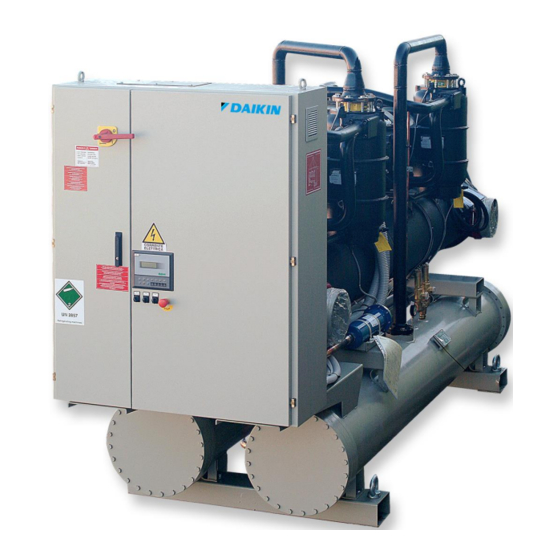
- Page 1 Installation, Operation and Maintenance Manual D–EIMWC00508-16EN Water-cooled screw chillers EWWQ380B-SS~EWWQC20B-SS EWWQ420B-XS~EWWQC21B-XS 50Hz – Refrigerant: R-410A Original Instructions...
-
Page 2: Table Of Contents
Contents General information………………………………………………………………………………………………………………….4 Warnings for the operator ..............................4 Assistance ..................................4 Spare parts ..................................4 Receiving the machine ............................... 4 Checks ....................................5 Purpose of this manual ............................... 5 Important information on the refrigerant used ........................5 Operating limits ................................... 6 Storing .................................... - Page 3 Refrigerant side measurements ............................40 Electrical measurements ..............................40 Service and limited warranty............................41 Obligatory routine checks and starting up apparatuses under pressure ..............42 Important information regarding the refrigerant used ....................42 List of tables Table 1 – Acceptable water quality limits ..........................11 Table 2 - Typical operating conditions with compressors at 100% ..................
-
Page 4: General Information
General information IMPORTANT The units described in the present manual represent a valuable investment. Maximum care should be taken to ensure correct installation and appropriate working conditions of the units. Installation and maintenance must be performed by qualified and specifically trained personnel only. Correct maintenance of the unit is indispensable for its safety and reliability. -
Page 5: Checks
Checks To prevent the possibility of incomplete delivery (missing parts) or transportation damage, please perform the following checks upon receipt of the machine: Before accepting the machine, please verify every single component in the consignment. Check for any damage. In the event that the machine has been damaged, do not remo ve the damaged material. A set of photographs are helpful in ascertaining responsibility. -
Page 6: Operating Limits
Two Compressors Unit 1 – Unit nameplate data 6 – Non flammable gas symbol 2 – Lifting instructions 7 – Manufacturer’s logo 3 – Hazardous Voltage warning 8 – Gas type 4 – Cable tightening warning 9 – Electrical hazard symbol 5 –... -
Page 7: Mechanical Installation
Mechanical Installation Shipping The stability of the machine during shipping must be ensured. If the machine is shipped with a wooden cross-plank on its base, the cross-plank must be removed only after the final destination has been reached. Responsibility The manufacturer declines all responsibility, present and future, for any damage to persons, animals or property caused by negligence of operators failing to follow the installation and maintenance instructions in this manual. -
Page 8: Fig. 1 - Lifting The Unit
Fig. 1 - Lifting the unit D-EIMWC00508-16EN - 8/48... -
Page 9: Positioning And Assembly
WARNING Both the lifting ropes and the spacing bar and/or scales must be strong enough to support the machine safely. Please check the unit’s weight on the machine’s nameplate. The weights shown in the "Technical data" tables in the "General Information" chapter refer to standard units. Some specific machines might have accessories that increase their overall weight (heat recovery, etc.) WARNING The machine must be lifted with the utmost attention and care. -
Page 10: Fig. 3 - Water Piping Connection For Heat Recovery Exchangers
Anti-vibration mountings in order to reduce transmission of vibrations to the underlying structure. Isolating valves to isolate the machine from the water system during service. Manual or automatic air venting device at the system’s highest point; drain device at the system’s lowest point. Neither the evaporator nor the heat recovery device must be positioned at the system’s highest point. -
Page 11: Water Treatment
ATTENTION Install a mechanical filter on the inlet to each heat exchanger. Failure to install a mechanical filter allows solid particles and/or welding slag to enter the exchanger. Installation of a filter with a mesh size not exceeding 0.5 mm in diameter is advised. -
Page 12: Fig. 4 - Adjusting The Safety Flow Switch
3” 83 mm 4” 107 mm 5” 134 mm 6” 162 mm 5 mm For 3” - 6” piping Adjusting the flow switch’s Use paddle b = 29 mm trigger sensitivity Fig. 4 - Adjusting the safety flow switch Refrigerating circuit safety valves Each system comes with safety valves that are installed on each circuit, both on the evaporator and on the condenser. -
Page 13: Electrical Installation
Electrical Installation General specifications CAUTION All electrical connections to the machine must be carried out in compliance with laws and regulations in force. All installation, operating and maintenance activities must be carried out by qualified personnel. Please refer to the specific wiring diagram for the machine that you have purchased and whi ch was sent with the unit. Should the wiring diagram not appear on the machine or should it have been lost, please contact your dealer who will provide for a copy to be forwarded. -
Page 14: Electrical Components
Electrical components All power and interface electrical connections are specified in the wiring diagram that is shipped with the machine. The installer must supply the following components: Power supply wires (dedicated conduit) Interconnection and interface wires (dedicated conduit) Thermal-magnetic circuit breaker of suitable size (please see electrical data). Electrical wiring Power circuit: Connect the electrical power supply cables to the terminals of the general circuit breaker on the machine’s... -
Page 15: External Water Setpoint Reset - Electrical Wiring (Optional)
External water Setpoint reset – Electrical wiring (Optional) The machine’s local setpoint can be modified by means of an external analogue 4-20 mA signal. Once this function has been enabled, the microprocessor allows to modify the setpoint from the set local value up to a differential of 3°C. 4 mA corresponds to a 0°C differential, 20 mA corresponds to the setpoint plus the maximum differential. - Page 16 Digital Outputs Double Set Point Esternal Fault Evaporator Flow Switch EFS-1 Evaporator Flow Switch 1 EFS-2 Evaporator Flow Switch 2 General Alarm Condensator Water Pump KPE-1 Evaporator Water Pump 1 KPE-2 Evaporator Water Pump 2 D–EIMWC00508-16EN - 16/48...
-
Page 17: Operation
Operation Operator’s responsibilities It is important that the operator is appropriately trained and becomes familiar with the system before operating the machine. In addition to reading this manual, the operator must study the microprocessor operating manual and the wiring diagram in order to understand start-up sequence, operation, shutdown sequence and operation of all the safety devices. During the machine’s initial start-up phase, a technician authorized by the manufacturer is available to answer any questions and to give instructions as to the correct operating procedures. -
Page 18: Fig. 6- Refrigeration Cycle Of The Ewwq B-Ss / Ewwq B-Xs Dual Fr4 Unit
Fig. 6- Refrigeration cycle of the EWWQ B-SS / EWWQ B-XS DUAL Fr4 unit ELECTRONIC EXP. VALVE WATER WATER OUTLET INLET EVAPORATOR EVAPORATOR HEATER ELECTRONIC EXP. VALVE F12-22 LP LOW PRESSURE SWITCH F13-23 HP HIGH PRESSURE SWITCH WH1-2 HIGH PRESSURE TRANSDUCER (0 ÷ 45 bar) WL1-2 LOW PRESSURE TRANSDUCER (0 ÷... -
Page 19: Fig. 7 - Refrigeration Cycle Of The Ewwq B-Ss / Ewwq B-Xs Mono Fr4 Unit
Fig. 7 - Refrigeration cycle of the EWWQ B-SS / EWWQ B-XS Mono Fr4 unit ELECTRONIC EXP. VALVE WATER WATER OUTLET EVAPORATOR INLET F12-22 LP LOW PRESSURE SWITCH F13-23 HP HIGH PRESSURE SWITCH WH1-2 HIGH PRESSURE TRANSDUCER (0 ÷ 45 bar) WL1-2 LOW PRESSURE TRANSDUCER (0 ÷... -
Page 20: Fig. 8 - Refrigeration Cycle Of The Ewwq B-Ss / Ewwq B-Xs Dual 3200 Unit
Fig. 8 - Refrigeration cycle of the EWWQ B-SS / EWWQ B-XS DUAL 3200 unit F12-22 LP LOW PRESSURE SWITCH F13-23 HP HIGH PRESSURE SWITCH WH1-2 HIGH PRESSURE TRANSDUCER (0 ÷ 45 bar) WL1-2 LOW PRESSURE TRANSDUCER (0 ÷ 30 bar) WD1-2 OIL TEMPERATURE LEAVING WATER TEMPERATURE... -
Page 21: Fig. 9 - Refrigeration Cycle Of The Ewwq B-Ss / Ewwq B-Xs Mono 3200 Unit
Fig. 9 - Refrigeration cycle of the EWWQ B-SS / EWWQ B-XS Mono 3200 unit F12-22 LP LOW PRESSURE SWITCH F13-23 HP HIGH PRESSURE SWITCH WH1-2 HIGH PRESSURE TRANSDUCER (0 ÷ 45 bar) WL1-2 LOW PRESSURE TRANSDUCER (0 ÷ 30 bar) WD1-2 OIL TEMPERATURE LEAVING WATER TEMPERATURE... -
Page 22: Description Of The Refrigeration Cycle With Partial Heat Recovery
Description of the refrigeration cycle with partial heat recovery The low-temperature refrigerant gas from the evaporator is drawn by the compressor through the electric motor, which is cooled by the refrigerant. It is subsequently compressed and during this process the refrigerant mixes with the oil from the oil separator. -
Page 23: Compression Process
Fig. 10 - Picture of Fr4100 compressor Fig. 11 – Picture of Fr3200 compressor In the Fr3200 and Fr4100 series compressor, access to internal parts is allowed by two covers positioned sidewise. Compression process With the single-screw compressor the suction, compression and discharge process takes place in a continuous manner thanks to the upper satellite. -
Page 24: Fig. 12 - Compression Process
1. E 2. Suction Main rotor flutes ‘a’, ‘b’ and ‘c’ are in communication at one end with the suction chamber and are sealed at the other end by the upper satellite teeth. As the main rotor turns, the effective length of the flutes increases, thus increasing the volume open to the suction chamber. -
Page 25: Fig. 13- Refrigeration Capacity Control Mechanism Of Compressor Fr3200 - Fr4
FR3200 – FR4 Compressor Unload Load Fig. 13 - Refrigeration capacity control mechanism of compressor Fr3200 – D–EIMWC00508-16EN - 25/48... -
Page 26: Fig. 14 - Capacity Control Mechanism
Unload Spring Force + Oil Pressure Suction/Discharge Differential Pressure = Slide valve moves toward unload Load Suction/Discharge Differential Pressure > Spring Force = Slide valve moves toward load APACITY ONTROL CTION OLENOID VALVE OLENOID VALVE Load compressor Oil is vented from the capacity control cylinder. The suction/discharge Energised (open) De-energised differential pressure overcomes the force of the spring and moves the slide... -
Page 27: Pre-Startup Checks
Pre-startup checks General Once the machine has been installed, use the following procedure to check that it has been done correctly: CAUTION Switch off the power supply of the machine before performing any checks. Failure to open the power switches at this stage can result in serious injury to the operator or even death. Inspect all the electrical connections to the power circuits and to the compressors, including t he contactors, fuse carriers and electrical terminals and check that they are clean and well secured. -
Page 28: Units With External Water Pump
Units with external water pump Start the water pump and check the water system for any leaks; repair these if necessary. While the water pump is in operation, adjust the water flow until the design pressure drop for the evaporator is reached. Adjust the flow switch trigger point (not factory-supplied), to ensure operation of the machine within a ... -
Page 29: Startup Procedure
Startup procedure Turning on the machine With the general disconnecting switch Q10 closed, check that switches Q0, Q1, Q2 and Q12 are in the Off (or 0) position. Close the thermal-magnetic switch Q12 and wait for the microprocessor and the control to start. Check that the oil temperature is warm enough. -
Page 30: Seasonal Shutdown
IMPORTANT If the machine is not supplied with a built-in pump, do not shut down the external pump before 3 minutes have elapsed after the last compressor has shut down. Early shutdown of the pump triggers a water-flow failure alarm. Seasonal shutdown Turn switches Q1 and Q2 to the Off (or 0) position to shut down the compressors, using the normal pump-down procedure. -
Page 31: System Maintenance
System maintenance WARNING All routine and non-routine maintenance activities on the machine must be carried out solely by qualified personnel who are familiar with the machine characteristics, operation and maintenance procedures, and who are aware of the safety requirements and risks involved. WARNING It 's absolutely forbidden to remove all the protections of the moving parts of the unit WARNING... -
Page 32: Fig. 15 - Installation Of Control Devices For Fr4 Compressor
Fig. 15 - Installation of control devices for Fr4 compressor ECONOMIZER PORT ECONOMIZER PORT LIFTING HIGH PRESSURE SWITCH LIFTING DISCHARGE OIL CHARGE LOADING SOLENOID VALVE UNLOADING COCK SOLENOID VALVE TRANSDUCER FOR HIGH PRESSURE OIL FILTER OIL FILTER TEMPERATURE SENSOR POSITION TRANSDUCER FOR OIL PRESSURE HEATER SHEATH FOR OIL SUMP TRANSDUCER FOR OIL PRESSURE... -
Page 33: Replacement Of Filter Dryer
Routine maintenance Table 3 – Routine maintenance programme Activities Weekly Monthly Yearly (Note 1) (Note 2) General: Reading of operating data (Note 3) Visual inspection of machine for any damage and/or loosening Verification of thermal insulation integrity Clean and paint where necessary Analysis of water (Note 5) Electrical: Verification of control sequence... -
Page 34: Procedure To Replace The Filter Dryer Cartridge
Procedure to replace the filter dryer cartridge CAUTION Ensure proper water flow through the evaporator during the entire servicing period. Interrupting the water flow during this procedure would cause the evaporator to freeze, with consequent breakage of internal piping. Shut down the relevant compressor by turning the Q1 or Q2 switch to Off. Wait until the compressor has stopped and close the valve located on the liquid line. -
Page 35: Rplacement Of The Oil Filter
Once the compressor has stopped, place a label on the compressor start -up switch, to prevent undesired start-ups. Close the compressor suction valve (if any). Using a recovery unit, remove surplus refrigerant from the liquid filter until atmospheric pressure is reached. The refrigerant must be stored in a suitable and clean container. -
Page 36: Fr4 Compressor
Compatible oils: Mobile Eal Arctic 68 ICI Emkarate RL 68H The standard oil charge for a compressor is 16 litres. Procedure to replace oil filter Shut down both compressors by turning the Q1 and Q2 switches to the Off position. Turn the Q0 switch to Off, wait for the circulation pump to turn off and open the general disconnecting switch Q10 to cut off the machine’s electrical power supply. -
Page 37: Refrigerant Charge
ICI Emkarate RL 68H The standard oil charge for a compressor is 16 litres. Oil filter replacement procedure Procedure to replace oil filter Shut down both compressors by turning the Q1 and Q2 switches to the Off position. Turn the Q0 switch to Off, wait for the circulation pump to turn off and open the general disconnecting switch Q10 to cut off the machine’s electrical power supply. -
Page 38: Procedure To Replenish Refrigerant
The subcooling value is about 3-4°C. Once the subcooling section has been completely filled, additional refrigerant will not increase system efficiency. However, a small additional quantity of refrigerant (12 kg) makes the system slightly less sensitive. N.B.: Subcooling varies and requires a few minutes to re-stabilise. However, subcooling should not come below 2°C under any condition. -
Page 39: Standard Checks
Standard Checks Temperature and pressure sensors The unit comes factory-equipped with all the sensors listed below. Periodically check that their measurements are correct by means of reference instruments (manometers, thermometers); correct the wrong readings as necessary using the microprocessor keypad. Well-calibrated sensors ensure better efficiency for the machine and a longer lifetime. Note: Refer to the microprocessor use and maintenance manual for a complete description of applications, settings and adjustments. -
Page 40: Test Sheet
Test sheet It is recommended that the following operation data are recorded periodically in order to verify correct operation of the machine over time. These data will also be extremely useful to the technicians who will be performing routine and/or non- routine maintenance on the machine. -
Page 41: Service And Limited Warranty
Service and limited warranty All machines are factory-tested and guaranteed for 12 months as of the first start-up or 18 months as of delivery. These machines have been developed and constructed according to high quality standards ensuring years of failure-free operation. -
Page 42: Obligatory Routine Checks And Starting Up Apparatuses Under Pressure
Obligatory routine checks and starting up apparatuses under pressure The units are included in category IV of the classification according to European Directive PED 2014/68/EU. For chillers belonging to this category, some local regulations require a periodic inspection by an authorized agency. - Page 43 Factory and Field charged units instructions (Important information regarding the refrigerant used) The refrigerant system will be charged with fluorinated greenhouse gases. Do not vent gases into the atmosphere. 1 Fill in with indelible ink the refrigerant charge label supplied with the product as following instructions: the refrigerant charge for each circuit (1;...
- Page 44 Disposal The unit is made of metal and plastic parts. All these parts must be disposed of in accordance with the local regulations in terms of disposal. Lead batteries must be collected and taken to specific refuse collection centres. D–EIMWC00508-16EN - 44/48...
- Page 45 D–EIMWC00508-16EN - 45/48...
- Page 46 D–EIMWC00508-16EN - 46/48...
- Page 47 D–EIMWC00508-16EN - 47/48...
- Page 48 The present publication is drawn up by of information only and does not constitute an offer binding upon Daikin Applied Europe S.p.A.. Daikin Applied Europe S.p.A. has compiled the content of this publication to the best of its knowledge. No express or implied warranty is given for the completeness, accuracy, reliability or fitness for particular purpose of its content, and the products and services presented therein.