Table of Contents
Advertisement
Quick Links
Advertisement
Table of Contents

Related Manuals for Daikin Altherma 3 R MT F Series


Summary of Contents for Daikin Altherma 3 R MT F Series
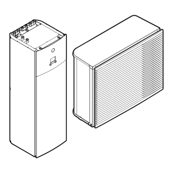
- Page 1 Installer reference guide Daikin Altherma 3 R MT F https://daikintechnicaldatahub.eu ▲= 1, 2, 3, …, 9, A, B, C, …, Z ERRA08E▲V3▼ ELVZ12S18E▲6V▼ ▼= , , 1, 2, 3, …, 9 ERRA10E▲V3▼ ELVZ12S23E▲6V▼ ERRA12E▲V3▼ ELVZ12S18E▲9W▼ ERRA08E▲W1▼ ELVz12S23E▲9W▼ ERRA10E▲W1▼ ERRA12E▲W1▼...
-
Page 2: Table Of Contents
7.1.5 Installation patterns ............................57 Opening and closing the units ............................65 7.2.1 About opening the units..........................65 7.2.2 To open the outdoor unit..........................65 Installer reference guide ERRA08~12E + ELVZ12S18+23E Daikin Altherma 3 R MT F 4P708478-1 – 2023.05... - Page 3 About preferential kWh rate power supply....................111 9.1.5 Overview of electrical connections except external actuators ..............112 Connections to the outdoor unit............................ 113 9.2.1 Specifications of standard wiring components....................113 ERRA08~12E + ELVZ12S18+23E Installer reference guide Daikin Altherma 3 R MT F 4P708478-1 – 2023.05...
- Page 4 Air purge function............................241 12.4.3 Operation test run............................243 12.4.4 Actuator test run ............................244 12.4.5 Underfloor heating screed dryout ......................... 245 13 Hand-over to the user Installer reference guide ERRA08~12E + ELVZ12S18+23E Daikin Altherma 3 R MT F 4P708478-1 – 2023.05...
- Page 5 Wiring diagram: Outdoor unit ............................283 17.5 Wiring diagram: Indoor unit ............................288 17.6 ESP curve: Indoor unit..............................294 18 Glossary 19 Field settings table ERRA08~12E + ELVZ12S18+23E Installer reference guide Daikin Altherma 3 R MT F 4P708478-1 – 2023.05...
-
Page 6: About This Document
The original instructions are written in English. All other languages are translations of the original instructions. Technical engineering data ▪ A subset of the latest technical data is available on the regional Daikin website (publicly accessible). ▪ The full set of latest technical data is available on the Daikin Business Portal (authentication required). -
Page 7: Meaning Of Warnings And Symbols
DANGER: RISK OF EXPLOSION Indicates a situation that could result in explosion. WARNING Indicates a situation that could result in death or serious injury. WARNING: FLAMMABLE MATERIAL ERRA08~12E + ELVZ12S18+23E Installer reference guide Daikin Altherma 3 R MT F 4P708478-1 – 2023.05... -
Page 8: Installer Reference Guide At A Glance
Various installation setups of the system Unit installation What to do and know to install the system, including information on how to prepare for an installation ERRA08~12E + ELVZ12S18+23E Installer reference guide Daikin Altherma 3 R MT F 4P708478-1 – 2023.05... - Page 9 Note: There is also an installer settings table in the user reference guide. This table has to be filled in by the installer and handed over to the user. ERRA08~12E + ELVZ12S18+23E Installer reference guide Daikin Altherma 3 R MT F 4P708478-1 – 2023.05...
-
Page 10: General Safety Precautions
WARNING Improper installation or attachment of equipment or accessories could result in electrical shock, short-circuit, leaks, fire or other damage to the equipment. ONLY use accessories, optional equipment and spare parts made or approved by Daikin unless otherwise specified. WARNING Make sure installation, testing and applied materials comply with applicable legislation (on top of the instructions described in the Daikin documentation). -
Page 11: Installation Site
▪ Use a separate recovery system so that the unit's compressor does NOT have to operate. ERRA08~12E + ELVZ12S18+23E Installer reference guide Daikin Altherma 3 R MT F 4P708478-1 – 2023.05... - Page 12 ONLY use tools exclusively for the refrigerant type used in the system, this to ensure pressure resistance and prevent foreign materials from entering into the system. ▪ Charge the liquid refrigerant as follows: ERRA08~12E + ELVZ12S18+23E Installer reference guide Daikin Altherma 3 R MT F 4P708478-1 – 2023.05...
-
Page 13: Water
If NOT factory installed, a main switch or other means for disconnection, having a contact separation in all poles providing full disconnection under overvoltage category III condition, MUST be installed in the fixed wiring. ERRA08~12E + ELVZ12S18+23E Installer reference guide Daikin Altherma 3 R MT F 4P708478-1 – 2023.05... - Page 14 Use an appropriate screwdriver for tightening the terminal screws. A screwdriver with a small head will damage the head and make proper tightening impossible. ▪ Over-tightening the terminal screws may break them. ERRA08~12E + ELVZ12S18+23E Installer reference guide Daikin Altherma 3 R MT F 4P708478-1 – 2023.05...
- Page 15 ON and OFF while the product is operating, attach a reversed phase protection circuit locally. Running the product in reversed phase can break the compressor and other parts. ERRA08~12E + ELVZ12S18+23E Installer reference guide Daikin Altherma 3 R MT F 4P708478-1 – 2023.05...
-
Page 16: Specific Installer Safety Instructions
(example: open flames, an operating gas appliance or an operating electric heater). WARNING DO NOT reuse refrigerant piping that has been used with any other refrigerant. Replace the refrigerant pipes or clean thoroughly. ERRA08~12E + ELVZ12S18+23E Installer reference guide Daikin Altherma 3 R MT F 4P708478-1 – 2023.05... - Page 17 WARNING Make sure installation, servicing, maintenance and repair comply with instructions from Daikin and with applicable legislation and are executed ONLY by authorised persons. Installation patterns (see "7.1.5 Installation patterns" [...
- Page 18 Provide adequate measures to prevent that the unit can be used as a shelter by small animals. Small animals that make contact with electrical parts can cause malfunctions, smoke or fire. ERRA08~12E + ELVZ12S18+23E Installer reference guide Daikin Altherma 3 R MT F 4P708478-1 – 2023.05...
- Page 19 For a translation of its legend, see "17.5 Wiring diagram: Indoor unit" [ 288]. WARNING ALWAYS use multicore cable for power supply cables. ERRA08~12E + ELVZ12S18+23E Installer reference guide Daikin Altherma 3 R MT F 4P708478-1 – 2023.05...
- Page 20 INFORMATION Details of type and rating of fuses, or rating of circuit breakers are described in "9 Electrical installation" [ 108]. ERRA08~12E + ELVZ12S18+23E Installer reference guide Daikin Altherma 3 R MT F 4P708478-1 – 2023.05...
- Page 21 DANGER: RISK OF BURNING/SCALDING The water in the tank can be very hot. Troubleshooting (see "15 Troubleshooting" [ 258]) DANGER: RISK OF ELECTROCUTION ERRA08~12E + ELVZ12S18+23E Installer reference guide Daikin Altherma 3 R MT F 4P708478-1 – 2023.05...
- Page 22 See: ▪ "7.3.6 To install the discharge grille" [ 75] ▪ "7.3.7 To remove the discharge grille, and put the grille in safety position" [ 77] ERRA08~12E + ELVZ12S18+23E Installer reference guide Daikin Altherma 3 R MT F 4P708478-1 – 2023.05...
-
Page 23: About The Box
To avoid injury, do NOT touch the air inlet or aluminium fins of the unit. Crane Keep the slings within the marked area to not damage the unit. ERRA08~12E + ELVZ12S18+23E Installer reference guide Daikin Altherma 3 R MT F 4P708478-1 – 2023.05... -
Page 24: To Unpack The Outdoor Unit
After unpacking, carry the unit using the slings attached to the unit. See also: ▪ "4.1.2 To unpack the outdoor unit" [ 24] ▪ "7.3.4 To install the outdoor unit" [ 73] 4.1.2 To unpack the outdoor unit ERRA08~12E + ELVZ12S18+23E Installer reference guide Daikin Altherma 3 R MT F 4P708478-1 – 2023.05... -
Page 25: To Remove The Accessories From The Outdoor Unit
Multilingual fluorinated greenhouse gases label i Fluorinated greenhouse gases label j Energy label k Discharge grille (upper + lower part) l Installation manual – Discharge grille ERRA08~12E + ELVZ12S18+23E Installer reference guide Daikin Altherma 3 R MT F 4P708478-1 – 2023.05... -
Page 26: Indoor Unit
Differential pressure bypass valve c Mounting plate (+ screw) for demand PCB (EKRP1AHTA) and digital I/O PCB (EKRP1HBAA) d Declaration of conformity e Addendum book for optional equipment ERRA08~12E + ELVZ12S18+23E Installer reference guide Daikin Altherma 3 R MT F 4P708478-1 – 2023.05... -
Page 27: To Handle The Indoor Unit
Handles at the back of the unit b Handles at the bottom of the unit. Carefully tilt the unit to the back so that the handles become visible. ERRA08~12E + ELVZ12S18+23E Installer reference guide Daikin Altherma 3 R MT F 4P708478-1 – 2023.05... -
Page 28: About The Units And Options
European refrigerant split outdoor pair heat pump High water temperature – ambient zone 2 (see operation range) Refrigerant R32 Capacity class Model series Power supply: V3=1N~, 220~240 V, 50 Hz W1=3N~, 380~415 V, 50 Hz ERRA08~12E + ELVZ12S18+23E Installer reference guide Daikin Altherma 3 R MT F 4P708478-1 – 2023.05... -
Page 29: Identification Label: Indoor Unit
Multi-zoning wired controls You can connect the following multi-zoning wired controls: ▪ Multi-zoning base unit 230 V (EKWUFHTA1V3) ▪ Digital thermostat 230 V (EKWCTRDI1V3) ▪ Analogue thermostat 230 V (EKWCTRAN1V3) ERRA08~12E + ELVZ12S18+23E Installer reference guide Daikin Altherma 3 R MT F 4P708478-1 – 2023.05... - Page 30 As an option the remote outdoor sensor can be installed to measure the outdoor temperature on another location (e.g. to avoid direct sunlight) to have an improved system behaviour. ERRA08~12E + ELVZ12S18+23E Installer reference guide Daikin Altherma 3 R MT F 4P708478-1 – 2023.05...
- Page 31 For installation instructions, see the installation and operation manual of the Human Comfort Interface (HCI) as room thermostat, and the addendum book for optional equipment. ERRA08~12E + ELVZ12S18+23E Installer reference guide Daikin Altherma 3 R MT F 4P708478-1 – 2023.05...
-
Page 32: Possible Combinations Of Indoor Unit And Outdoor Unit
For installation instructions, see "9.3.10 To connect a Smart Grid" [ 135]. 5.2.3 Possible combinations of indoor unit and outdoor unit Indoor unit Outdoor unit ERRA08 ERRA10 ERRA12 ELVZ12 ERRA08~12E + ELVZ12S18+23E Installer reference guide Daikin Altherma 3 R MT F 4P708478-1 – 2023.05... -
Page 33: Application Guidelines
Setting up the domestic hot water tank ▪ Setting up the energy metering ▪ Setting up the power consumption control ▪ Setting up an external temperature sensor ERRA08~12E + ELVZ12S18+23E Installer reference guide Daikin Altherma 3 R MT F 4P708478-1 – 2023.05... -
Page 34: Setting Up The Space Heating/Cooling System
NOTICE A differential pressure bypass valve can be integrated in the system. Keep in mind that this valve might not be shown on the illustrations. ERRA08~12E + ELVZ12S18+23E Installer reference guide Daikin Altherma 3 R MT F 4P708478-1 – 2023.05... -
Page 35: Multiple Rooms - Two Lwt Zones
In cooling: 12°C In cooling mode, you can allow the underfloor heating (main zone) to provide refreshment (no real cooling), or NOT allow it. See setup below. ERRA08~12E + ELVZ12S18+23E Installer reference guide Daikin Altherma 3 R MT F 4P708478-1 – 2023.05... - Page 36 In this case, the main zone cooling setpoint will NOT be adjustable. The cooling setpoint for the heat pump convectors can be adjusted via the additional zone setpoint screen. ERRA08~12E + ELVZ12S18+23E Installer reference guide Daikin Altherma 3 R MT F 4P708478-1 – 2023.05...
- Page 37 Set to follow the thermo demand of the main zone. Shut-off valve If the main zone must be shut off during cooling mode to prevent condensation on the floor, set it accordingly. ERRA08~12E + ELVZ12S18+23E Installer reference guide Daikin Altherma 3 R MT F 4P708478-1 – 2023.05...
-
Page 38: Setting Up The Domestic Hot Water Tank
Typical water volume How many showers are needed per 1 shower = 10 min×10 l/min = 100 l day? How many baths are needed per day? 1 bath = 150 l ERRA08~12E + ELVZ12S18+23E Installer reference guide Daikin Altherma 3 R MT F 4P708478-1 – 2023.05... - Page 39 (EKECBU*) can increase this temperature if it is installed and activated. However, this consumes more energy. We recommend to set the desired storage tank temperature below 62°C to avoid using the electrical resistance. ERRA08~12E + ELVZ12S18+23E Installer reference guide Daikin Altherma 3 R MT F 4P708478-1 – 2023.05...
-
Page 40: Setup And Configuration - Dhw Tank
129]. ▪ For more information about connecting the recirculation connection, see "8.6.4 To connect the recirculation piping" [ 107]. Configuration ▪ For more information, see "11 Configuration" [ 142]. ERRA08~12E + ELVZ12S18+23E Installer reference guide Daikin Altherma 3 R MT F 4P708478-1 – 2023.05... -
Page 41: Dhw Pump For Disinfection
Via the user interface, you can read out the following energy data: Produced heat Consumed energy ▪ You can read out the energy data: For space heating For space cooling For domestic hot water production ERRA08~12E + ELVZ12S18+23E Installer reference guide Daikin Altherma 3 R MT F 4P708478-1 – 2023.05... -
Page 42: Produced Heat
Requires external power meters. ▪ Setup and configuration: When using electrical power meters, set the number of pulses/kWh for each power meter via the user interface. ERRA08~12E + ELVZ12S18+23E Installer reference guide Daikin Altherma 3 R MT F 4P708478-1 – 2023.05... -
Page 43: Normal Kwh Rate Power Supply
▪ Three-phase outdoor unit Three-phase ▪ Backup heater supplied from a three- phase grid, i.e. the backup heater model is: *6V (6T1: 3~ 230 V) *9W (3N~ 400 V) ERRA08~12E + ELVZ12S18+23E Installer reference guide Daikin Altherma 3 R MT F 4P708478-1 – 2023.05... -
Page 44: Preferential Kwh Rate Power Supply
Power meter 2: Measures the rest (i.e. indoor unit and backup heater). Setup ▪ Connect power meter 1 to X5M/5 and X5M/6. ▪ Connect power meter 2 to X5M/3 and X5M/4. "9.3.4 To connect the electricity meters" [ 128]. ERRA08~12E + ELVZ12S18+23E Installer reference guide Daikin Altherma 3 R MT F 4P708478-1 – 2023.05... -
Page 45: Setting Up The Power Consumption Control
Allows you to limit the power consumption of the entire heat pump system (sum of indoor unit and backup heater) via 4 digital inputs. ▪ Limitation of power in kW or current in A. ERRA08~12E + ELVZ12S18+23E Installer reference guide Daikin Altherma 3 R MT F 4P708478-1 – 2023.05... -
Page 46: Permanent Power Limitation
Power input t Time DI Digital input (power limitation level) a Power limitation active b Actual power input Setup and configuration ▪ No additional equipment needed. ERRA08~12E + ELVZ12S18+23E Installer reference guide Daikin Altherma 3 R MT F 4P708478-1 – 2023.05... -
Page 47: Power Limitation Activated By Digital Inputs
6.5.2 Power limitation activated by digital inputs Power limitation is also useful in combination with an energy management system. The power or current of the entire Daikin system is limited dynamically by digital inputs (maximum four steps). Each power limitation level is set via the user interface by limiting one of the following: ▪... -
Page 48: Power Limitation Process
Produced heat Consumed energy A Outdoor unit B Backup heater a Limited outdoor unit operation b Full outdoor unit operation c Backup heater step 1 turned ON ERRA08~12E + ELVZ12S18+23E Installer reference guide Daikin Altherma 3 R MT F 4P708478-1 – 2023.05... -
Page 49: Bbr16 Power Limitation
In case Smart Grid Forced off mode is active, the outdoor unit compressor and electrical heaters will NOT operate. Setup and configuration "9.3.10 To connect a Smart Grid" [ 135] and "Benefit kWh power supply" [ 221]. ERRA08~12E + ELVZ12S18+23E Installer reference guide Daikin Altherma 3 R MT F 4P708478-1 – 2023.05... -
Page 50: Setting Up An External Temperature Sensor
To protect the outdoor unit, the internal sensor of the outdoor unit is always used. ERRA08~12E + ELVZ12S18+23E Installer reference guide Daikin Altherma 3 R MT F 4P708478-1 – 2023.05... -
Page 51: Unit Installation
▪ radiators in the additional zone, this is the zone with the highest water temperature. ERRA08~12E + ELVZ12S18+23E Installer reference guide Daikin Altherma 3 R MT F 4P708478-1 – 2023.05... -
Page 52: Installation Site Requirements Of The Outdoor Unit
NOT directly exposed to the wind. a Baffle plate b Prevailing wind direction c Air outlet Do NOT install the unit in the following places: ERRA08~12E + ELVZ12S18+23E Installer reference guide Daikin Altherma 3 R MT F 4P708478-1 – 2023.05... -
Page 53: Additional Installation Site Requirements Of The Outdoor Unit In Cold Climates
7.1.2 Additional installation site requirements of the outdoor unit in cold climates Protect the outdoor unit against direct snowfall and take care that the outdoor unit is NEVER snowed up. ERRA08~12E + ELVZ12S18+23E Installer reference guide Daikin Altherma 3 R MT F 4P708478-1 – 2023.05... -
Page 54: Installation Site Requirements Of The Indoor Unit
Install the indoor unit at a minimum distance of 1 m from other heat sources (>80°C) (e.g. electrical heater, oil heater, chimney) and combustible materials. Otherwise the unit may be damaged or in extreme cases catch fire. ERRA08~12E + ELVZ12S18+23E Installer reference guide Daikin Altherma 3 R MT F 4P708478-1 – 2023.05... -
Page 55: Special Requirements For R32 Units
Do NOT use means to accelerate the defrosting process or to clean the equipment, other than those recommended by the manufacturer. ▪ Be aware that R32 refrigerant does NOT contain an odour. ERRA08~12E + ELVZ12S18+23E Installer reference guide Daikin Altherma 3 R MT F 4P708478-1 – 2023.05... - Page 56 Joints made in installation between parts of refrigerant system shall be accessible for maintenance purposes. WARNING Make sure installation, servicing, maintenance and repair comply with instructions from Daikin and with applicable legislation and are executed ONLY by authorised persons. NOTICE ▪...
-
Page 57: Installation Patterns
If no chimney is installed, this is the default point of release in case of refrigerant leakage. If needed, you can connect a chimney here. Chimney Bottom opening for natural ventilation Top opening for natural ventilation ERRA08~12E + ELVZ12S18+23E Installer reference guide Daikin Altherma 3 R MT F 4P708478-1 – 2023.05... - Page 58 Unit's connection point for the chimney = 1" male thread. Use a compatible counterpart for the chimney. ▪ Make sure the connection is airtight. ▪ The chimney material is unimportant. ERRA08~12E + ELVZ12S18+23E Installer reference guide Daikin Altherma 3 R MT F 4P708478-1 – 2023.05...
- Page 59 ▪ Must be ≥50% of A (minimum bottom opening area). nv-min Min. 50% ▪ Must be ≥1.5 m from the floor. of A nv-min (≥A nv-min ERRA08~12E + ELVZ12S18+23E Installer reference guide Daikin Altherma 3 R MT F 4P708478-1 – 2023.05...
- Page 60 Ventilation openings must comply with A and with nv-min "Conditions ventilation openings" on previous page). Min. 50% Min. 50% ΔH1 of A of A nv-min nv-min (≥A (≥A nv-min nv-min ERRA08~12E + ELVZ12S18+23E Installer reference guide Daikin Altherma 3 R MT F 4P708478-1 – 2023.05...
- Page 61 1.91 m 1.74 m 3.65 kg 3.96 m 2.64 m 2.26 m 2.02 m 1.84 m 1.71 m 3.85 kg 4.18 m 2.79 m 2.38 m 2.13 m 1.95 m 1.80 m 1.68 m 4.05 kg 4.40 m 2.93 m 2.51 m 2.24 m 2.05 m 1.89 m 1.77 m ERRA08~12E + ELVZ12S18+23E Installer reference guide Daikin Altherma 3 R MT F 4P708478-1 – 2023.05...
- Page 62 1.498 dm² 0.792 dm² 1.86 m 5.369 dm² 3.401 dm² 2.562 dm² 1.789 dm² 1.002 dm² 0.209 dm² 2.06 m 4.700 dm² 2.629 dm² 1.681 dm² 0.809 dm² 2.26 m 4.103 dm² 1.934 dm² 0.886 dm² 2.46 m 3.565 dm² 1.302 dm² 0.160 dm² 2.66 m 3.074 dm² 0.721 dm² ERRA08~12E + ELVZ12S18+23E Installer reference guide Daikin Altherma 3 R MT F 4P708478-1 – 2023.05...
- Page 63 Floor area of room A (m²) [! NOT room A + room B !] 4.00 m² 6.00 m² 8.00 m² 10.00 m² 12.00 m² 14.00 m² 16.00 m² 2.86 m 2.624 dm² 0.183 dm² 3.06 m 2.206 dm² ERRA08~12E + ELVZ12S18+23E Installer reference guide Daikin Altherma 3 R MT F 4P708478-1 – 2023.05...
- Page 64 For intermediate refrigerant charges, use the row with the higher value. Example: If the refrigerant charge is 3.5 kg, use the row of 3.55 kg. Total refrigerant charge (kg) (dm²) nv-min 3.25 kg 9.1 dm² 3.35 kg 9.2 dm² ERRA08~12E + ELVZ12S18+23E Installer reference guide Daikin Altherma 3 R MT F 4P708478-1 – 2023.05...
-
Page 65: Opening And Closing The Units
DANGER: RISK OF BURNING/SCALDING 1 Open the service cover. 2 If necessary, open the side cover. This is, for example, necessary in the following cases: ERRA08~12E + ELVZ12S18+23E Installer reference guide Daikin Altherma 3 R MT F 4P708478-1 – 2023.05... -
Page 66: To Remove The Transportation Stay
2 Remove the screws (5×) from the transportation stay. Remove the transportation stay and dispose of it. Keep 4 screws to attach the compressor cover piece (see "7.2.4 To attach the compressor cover piece" [ 67]). ERRA08~12E + ELVZ12S18+23E Installer reference guide Daikin Altherma 3 R MT F 4P708478-1 – 2023.05... -
Page 67: To Attach The Compressor Cover Piece
7.2.5 To close the outdoor unit NOTICE When closing the outdoor unit cover, make sure that the tightening torque does NOT exceed 4.1 N•m. 1 If necessary, close the side cover. ERRA08~12E + ELVZ12S18+23E Installer reference guide Daikin Altherma 3 R MT F 4P708478-1 – 2023.05... -
Page 68: To Open The Indoor Unit
7.2.6 To open the indoor unit Overview a Top panel b User interface panel c Switch box cover d Front panel e High voltage switch box cover ERRA08~12E + ELVZ12S18+23E Installer reference guide Daikin Altherma 3 R MT F 4P708478-1 – 2023.05... - Page 69 X 1 4 Y 3 Remove the switch box cover. 4× 4 If necessary, remove the front plate. This is, for example, necessary in the following cases: ERRA08~12E + ELVZ12S18+23E Installer reference guide Daikin Altherma 3 R MT F 4P708478-1 – 2023.05...
-
Page 70: To Lower The Switch Box On The Indoor Unit
1 Remove the fixing plate at the top of the unit. 2 Tilt the switch box to the front and lift it out of its hinges. ERRA08~12E + ELVZ12S18+23E Installer reference guide Daikin Altherma 3 R MT F 4P708478-1 – 2023.05... -
Page 71: To Close The Indoor Unit
7.3.1 About mounting the outdoor unit When You have to mount the outdoor and indoor unit before you can connect the refrigerant and water piping. ERRA08~12E + ELVZ12S18+23E Installer reference guide Daikin Altherma 3 R MT F 4P708478-1 – 2023.05... -
Page 72: Precautions When Mounting The Outdoor Unit
Use 4 sets of M12 anchor bolts, nuts and washers. Provide at least 150 mm of free space below the unit. Additionally, make sure the unit is positioned at least 100 mm above the maximum expected level of snow. Anchor points (mm) ERRA08~12E + ELVZ12S18+23E Installer reference guide Daikin Altherma 3 R MT F 4P708478-1 – 2023.05... -
Page 73: To Install The Outdoor Unit
To avoid injury, do NOT touch the air inlet or aluminium fins of the unit. 1 Carry the unit by its slings, and put it onto the installation structure. 2 Fix the unit to the installation structure. ERRA08~12E + ELVZ12S18+23E Installer reference guide Daikin Altherma 3 R MT F 4P708478-1 – 2023.05... -
Page 74: To Provide Drainage
(see the following figure). ERRA08~12E + ELVZ12S18+23E Installer reference guide Daikin Altherma 3 R MT F 4P708478-1 – 2023.05... -
Page 75: To Install The Discharge Grille
O-ring. Make sure the O-ring is installed correctly to prevent leakage. 7.3.6 To install the discharge grille INFORMATION Electrical wiring. Before installing the discharge grille, connect the electrical wiring. ERRA08~12E + ELVZ12S18+23E Installer reference guide Daikin Altherma 3 R MT F 4P708478-1 – 2023.05... - Page 76 4 Align and attach the left side. 5 Align and attach the middle part. 6 Align and attach the right side. ERRA08~12E + ELVZ12S18+23E Installer reference guide Daikin Altherma 3 R MT F 4P708478-1 – 2023.05...
-
Page 77: To Remove The Discharge Grille, And Put The Grille In Safety Position
75] ▪ "7.3.7 To remove the discharge grille, and put the grille in safety position" [ 77] 1 Remove the upper part of the discharge grille. ERRA08~12E + ELVZ12S18+23E Installer reference guide Daikin Altherma 3 R MT F 4P708478-1 – 2023.05... - Page 78 4 Align the ball stud and hook on the grille with their counterparts on the unit. 5 Insert the hook. 6 Insert the ball stud. ERRA08~12E + ELVZ12S18+23E Installer reference guide Daikin Altherma 3 R MT F 4P708478-1 – 2023.05...
-
Page 79: Mounting The Indoor Unit
3 Slide the indoor unit into position. 4 Adjust the height of the leveling feet to compensate for floor irregularities. The maximum allowed deviation is 1°. ≤1° ERRA08~12E + ELVZ12S18+23E Installer reference guide Daikin Altherma 3 R MT F 4P708478-1 – 2023.05... -
Page 80: To Connect The Drain Hose To The Drain
4 Reattach the side panel. Ensure the water can flow through the drain tube. It is recommended to use a tundish to collect the water. Option 1: Through the left side panel 3× ERRA08~12E + ELVZ12S18+23E Installer reference guide Daikin Altherma 3 R MT F 4P708478-1 – 2023.05... - Page 81 Unit installation Option 2: Through the right side panel 3× ERRA08~12E + ELVZ12S18+23E Installer reference guide Daikin Altherma 3 R MT F 4P708478-1 – 2023.05...
-
Page 82: Piping Installation
Also see "7.1.4 Special requirements for R32 units" [ 55] for additional requirements. ▪ Piping length: See "7.1.3 Installation site requirements of the indoor unit" [ 54]. ERRA08~12E + ELVZ12S18+23E Installer reference guide Daikin Altherma 3 R MT F 4P708478-1 – 2023.05... -
Page 83: Refrigerant Piping Insulation
Insert refrigerant piping into the outdoor unit as straight as possible. If necessary, ensure that piping bends are not placed close to the rubber grommet. ERRA08~12E + ELVZ12S18+23E Installer reference guide Daikin Altherma 3 R MT F 4P708478-1 – 2023.05... -
Page 84: About Connecting The Refrigerant Piping
▪ Use caution when passing copper tubes through walls (see figure below). ERRA08~12E + ELVZ12S18+23E Installer reference guide Daikin Altherma 3 R MT F 4P708478-1 – 2023.05... -
Page 85: Guidelines When Connecting The Refrigerant Piping
8.2.4 Pipe bending guidelines Use a pipe bender for bending. All pipe bends should be as gentle as possible (bending radius should be 30~40 mm or larger). ERRA08~12E + ELVZ12S18+23E Installer reference guide Daikin Altherma 3 R MT F 4P708478-1 – 2023.05... -
Page 86: To Flare The Pipe End
▪ Set the nitrogen pressure to 20 kPa (0.2 bar) (just enough so it can be felt on the skin) with a pressure-reducing valve. ERRA08~12E + ELVZ12S18+23E Installer reference guide Daikin Altherma 3 R MT F 4P708478-1 – 2023.05... -
Page 87: Using The Stop Valve And Service Port
ERRA08~12E + ELVZ12S18+23E Installer reference guide Daikin Altherma 3 R MT F 4P708478-1 – 2023.05... -
Page 88: To Connect The Refrigerant Piping To The Outdoor Unit
Piping protection. Protect the field piping against physical damage. 1 Open the outdoor unit step 1 and 2 ("7.2.2 To open the outdoor unit" [ 65]). 2 Detach the outer side of the rubber grommet. ERRA08~12E + ELVZ12S18+23E Installer reference guide Daikin Altherma 3 R MT F 4P708478-1 – 2023.05... - Page 89 NOTICE Any exposed piping might cause condensation. 6 Reattach the outer side of the rubber grommet. ERRA08~12E + ELVZ12S18+23E Installer reference guide Daikin Altherma 3 R MT F 4P708478-1 – 2023.05...
-
Page 90: To Connect The Refrigerant Piping To The Indoor Unit
8.3.1 About checking the refrigerant piping The outdoor unit's internal refrigerant piping has been factory tested for leaks. You only have to check the outdoor unit's external refrigerant piping. ERRA08~12E + ELVZ12S18+23E Installer reference guide Daikin Altherma 3 R MT F 4P708478-1 – 2023.05... -
Page 91: Precautions When Checking The Refrigerant Piping
8.3.3 Checking refrigerant piping: Setup a Pressure gauge b Nitrogen c Refrigerant d Weighing scale e Vacuum pump f Stop valve ERRA08~12E + ELVZ12S18+23E Installer reference guide Daikin Altherma 3 R MT F 4P708478-1 – 2023.05... -
Page 92: To Check For Leaks
5 If you do NOT reach the target vacuum or CANNOT maintain the vacuum for 1 hour, do the following: ▪ Check for leaks again. ▪ Perform vacuum drying again. ERRA08~12E + ELVZ12S18+23E Installer reference guide Daikin Altherma 3 R MT F 4P708478-1 – 2023.05... -
Page 93: Charging Refrigerant
2 The outdoor unit's external refrigerant piping is checked (leak test, vacuum drying). 3 Vacuum drying on the outdoor unit's internal refrigerant piping is performed. ERRA08~12E + ELVZ12S18+23E Installer reference guide Daikin Altherma 3 R MT F 4P708478-1 – 2023.05... - Page 94 1 Determining how much refrigerant to charge. 2 Charging refrigerant. 3 Filling in the fluorinated greenhouse gases label, and fixing it to the inside of the outdoor unit. ERRA08~12E + ELVZ12S18+23E Installer reference guide Daikin Altherma 3 R MT F 4P708478-1 – 2023.05...
-
Page 95: Precautions When Charging Refrigerant
1 Connect the refrigerant cylinder to the service port of the gas stop valve. 2 Charge the additional refrigerant amount. 3 Open the stop valves. ERRA08~12E + ELVZ12S18+23E Installer reference guide Daikin Altherma 3 R MT F 4P708478-1 – 2023.05... -
Page 96: Completely Recharging Refrigerant
4 Charge the complete refrigerant amount. 5 Deactivate the vacuum mode (see "To activate/deactivate the vacuum mode field setting" [ 96]). 6 Open the gas stop valve. ERRA08~12E + ELVZ12S18+23E Installer reference guide Daikin Altherma 3 R MT F 4P708478-1 – 2023.05... -
Page 97: To Fix The Fluorinated Greenhouse Gases Label
Deformation of the piping can cause malfunctioning of the unit. ▪ Connecting piping – Tools. Only use appropriate tooling to handle brass, which is a soft material. If NOT, pipes will get damaged. ERRA08~12E + ELVZ12S18+23E Installer reference guide Daikin Altherma 3 R MT F 4P708478-1 – 2023.05... - Page 98 NOT exceeded. The minimum water pressure to operate is 1 bar (=0.1 MPa). ▪ Water temperature. All installed piping and piping accessories (valve, connections,…) MUST withstand the following temperatures: ERRA08~12E + ELVZ12S18+23E Installer reference guide Daikin Altherma 3 R MT F 4P708478-1 – 2023.05...
- Page 99 "6.3.5 DHW pump for disinfection" [ 41]. ▪ Thermostatic mixing valves. In accordance with the applicable legislation, it may be necessary to install thermostatic mixing valves. ERRA08~12E + ELVZ12S18+23E Installer reference guide Daikin Altherma 3 R MT F 4P708478-1 – 2023.05...
-
Page 100: Formula To Calculate The Expansion Vessel Pre-Pressure
When circulation in each space heating/cooling loop is controlled by remotely controlled valves, it is important that the minimum water volume is guaranteed, even if all of the valves are closed. ERRA08~12E + ELVZ12S18+23E Installer reference guide Daikin Altherma 3 R MT F 4P708478-1 – 2023.05... - Page 101 Use the following graph to determine the maximum water volume for the calculated pre-pressure. a Pre-pressure (bar) b Maximum water volume (l) Example: Maximum water volume and expansion vessel pre-pressure ERRA08~12E + ELVZ12S18+23E Installer reference guide Daikin Altherma 3 R MT F 4P708478-1 – 2023.05...
- Page 102 In case the minimum flow rate cannot be reached, a flow error 7H will be generated (no heating or operation). See the recommended procedure as described in "12.4 Checklist during commissioning" [ 239]. ERRA08~12E + ELVZ12S18+23E Installer reference guide Daikin Altherma 3 R MT F 4P708478-1 – 2023.05...
-
Page 103: Changing The Pre-Pressure Of The Expansion Vessel
The corresponding maximum water volume at 0.3 bar is 290 l. (See the graph in "Maximum water volume" [ 101]). ▪ Because 250 l is lower than 290 l, the expansion vessel is appropriate for the installation. ERRA08~12E + ELVZ12S18+23E Installer reference guide Daikin Altherma 3 R MT F 4P708478-1 – 2023.05... -
Page 104: Connecting Water Piping
1 Install the shut-off valves on the space heating water pipes. 2 Screw the indoor unit nuts on the shut-off valve. 3 Connect the domestic hot water in and out pipes to the indoor unit. ERRA08~12E + ELVZ12S18+23E Installer reference guide Daikin Altherma 3 R MT F 4P708478-1 – 2023.05... - Page 105 A pressure relief valve (field supply) with an opening pressure of maximum 10 bar (=1 MPa) must be installed on the domestic cold water inlet connection in accordance with the applicable legislation. ERRA08~12E + ELVZ12S18+23E Installer reference guide Daikin Altherma 3 R MT F 4P708478-1 – 2023.05...
- Page 106 Bypass Configuration. Set field setting [7-02]=0 (Number of zones = Single zone). NOTICE Install air purge valves at all local high points. ERRA08~12E + ELVZ12S18+23E Installer reference guide Daikin Altherma 3 R MT F 4P708478-1 – 2023.05...
-
Page 107: To Connect The Recirculation Piping
If the temperature is higher than 30°C and the humidity is higher than RH 80%, the thickness of the insulation materials should be at least 20 mm to prevent condensation on the surface of the insulation. ERRA08~12E + ELVZ12S18+23E Installer reference guide Daikin Altherma 3 R MT F 4P708478-1 – 2023.05... -
Page 108: Electrical Installation
The refrigerant piping is connected and checked ▪ The water piping is connected Typical workflow Connecting the electrical wiring typically consists of the following stages: ERRA08~12E + ELVZ12S18+23E Installer reference guide Daikin Altherma 3 R MT F 4P708478-1 – 2023.05... -
Page 109: Precautions When Connecting The Electrical Wiring
Do NOT push or place redundant cable length into the unit. NOTICE The distance between the high voltage and low voltage cables should be at least 50 mm. ERRA08~12E + ELVZ12S18+23E Installer reference guide Daikin Altherma 3 R MT F 4P708478-1 – 2023.05... -
Page 110: Guidelines When Connecting The Electrical Wiring
Single-core wire AA´ A´ Stranded conductor wire twisted to "solid-like" connection a Curled wire (single-core or twisted stranded conductor wire) b Screw c Flat washer ERRA08~12E + ELVZ12S18+23E Installer reference guide Daikin Altherma 3 R MT F 4P708478-1 – 2023.05... -
Page 111: About Electrical Compliance
E.g. time-of-use rates, seasonal rates, Wärmepumpentarif in Germany and Austria, ... This equipment allows for connection to such preferential kWh rate power supply delivery systems. ERRA08~12E + ELVZ12S18+23E Installer reference guide Daikin Altherma 3 R MT F 4P708478-1 – 2023.05... -
Page 112: Overview Of Electrical Connections Except External Actuators
1 Power supply for outdoor unit 2 Power supply and interconnection cable to indoor unit 3 Power supply for backup heater 4 Preferential kWh rate power supply (voltage free contact) ERRA08~12E + ELVZ12S18+23E Installer reference guide Daikin Altherma 3 R MT F 4P708478-1 – 2023.05... -
Page 113: Connections To The Outdoor Unit
30 mA – MUST comply with national wiring residual current device regulation MCA=Minimum circuit ampacity. Stated values are maximum values (see electrical data of combination with indoor units for exact values). ERRA08~12E + ELVZ12S18+23E Installer reference guide Daikin Altherma 3 R MT F 4P708478-1 – 2023.05... -
Page 114: To Connect The Electrical Wiring To The Outdoor Unit
▪ Connect the wires to the terminal block. ▪ Fix the cable with a cable tie. Wires: 1N+GND Maximum running current: Refer to name plate on unit. ERRA08~12E + ELVZ12S18+23E Installer reference guide Daikin Altherma 3 R MT F 4P708478-1 – 2023.05... - Page 115 ▪ Connect the wires to the terminal block (make sure the numbers match with the numbers on the indoor unit) and the earth screw. ▪ Fix the cable with a cable tie. Wires: (3+GND)×1.5 mm² — ERRA08~12E + ELVZ12S18+23E Installer reference guide Daikin Altherma 3 R MT F 4P708478-1 – 2023.05...
- Page 116 ▪ Connect the wires to the terminal block. ▪ Fix the cable with a cable tie. Wires: 3N+GND Maximum running current: Refer to name plate on unit. — ERRA08~12E + ELVZ12S18+23E Installer reference guide Daikin Altherma 3 R MT F 4P708478-1 – 2023.05...
- Page 117 ▪ Connect the wires to the terminal block (make sure the numbers match with the numbers on the indoor unit) and the earth screw. ▪ Fix the cable with a cable tie. Wires: (3+GND)×1.5 mm² — ERRA08~12E + ELVZ12S18+23E Installer reference guide Daikin Altherma 3 R MT F 4P708478-1 – 2023.05...
-
Page 118: To Reposition The Air Thermistor On The Outdoor Unit
9.2.3 To reposition the air thermistor on the outdoor unit This procedure is only necessary in areas with low ambient temperatures. Required accessory (delivered with the unit): Thermistor fixture. Click ERRA08~12E + ELVZ12S18+23E Installer reference guide Daikin Altherma 3 R MT F 4P708478-1 – 2023.05... -
Page 119: Connections To The Indoor Unit
For the main zone: ▪ [2.9] Control ▪ [2.A] Ext thermostat type For the additional zone: ▪ [3.A] Ext thermostat type ▪ [3.9] (read-only) Control ERRA08~12E + ELVZ12S18+23E Installer reference guide Daikin Altherma 3 R MT F 4P708478-1 – 2023.05... - Page 120 ▪ Installation manual of the remote indoor sensor ▪ Addendum book for optional equipment Wires: 2×0.75 mm² [9.B.1]=2 (External sensor = Room) [1.7] Room sensor offset ERRA08~12E + ELVZ12S18+23E Installer reference guide Daikin Altherma 3 R MT F 4P708478-1 – 2023.05...
- Page 121 Addendum book for optional equipment Wired room thermostat ▪ Installation manual of the wired room without multi-zoning base unit thermostat ▪ Addendum book for optional equipment ERRA08~12E + ELVZ12S18+23E Installer reference guide Daikin Altherma 3 R MT F 4P708478-1 – 2023.05...
-
Page 122: To Connect The Main Power Supply
2 Connect the main power supply. In case of normal kWh rate power supply Interconnection cable Wires: (3+GND)×1.5 mm² (= main power supply) — 1 2 3 ERRA08~12E + ELVZ12S18+23E Installer reference guide Daikin Altherma 3 R MT F 4P708478-1 – 2023.05... - Page 123 15 V DC, 10 mA. [9.8] Benefit kWh power supply Connect X11Y to X11YB. 1N~, 50 Hz, 230 V AC, 6.3 A 1 2 3 ERRA08~12E + ELVZ12S18+23E Installer reference guide Daikin Altherma 3 R MT F 4P708478-1 – 2023.05...
-
Page 124: To Connect The Backup Heater Power Supply
The backup heater capacity can vary, depending on the indoor unit model. Make sure that the power supply is in accordance with the backup heater capacity, as listed in the table below. ERRA08~12E + ELVZ12S18+23E Installer reference guide Daikin Altherma 3 R MT F 4P708478-1 – 2023.05... - Page 125 Connect the backup heater power supply as follows: Q1DI a Factory-mounted cable connected to the contactor of the backup heater, inside the switch box (K5M) b Field wiring (see table below) ERRA08~12E + ELVZ12S18+23E Installer reference guide Daikin Altherma 3 R MT F 4P708478-1 – 2023.05...
- Page 126 C. K5M Safety contactor (in the lower switch box) Q1DI Earth leakage circuit breaker (field supply) SWB Switch box X6M Terminal (field supply) ERRA08~12E + ELVZ12S18+23E Installer reference guide Daikin Altherma 3 R MT F 4P708478-1 – 2023.05...
-
Page 127: To Connect The Shut-Off Valve
3 Connect the valve control cable to the appropriate terminals as shown in the illustration below. NOTICE Wiring is different for a NC (normally closed) valve and a NO (normally open) valve. ERRA08~12E + ELVZ12S18+23E Installer reference guide Daikin Altherma 3 R MT F 4P708478-1 – 2023.05... -
Page 128: To Connect The Electricity Meters
2 User interface panel 3 Upper switch box cover 3 Connect the electricity meters cable to the appropriate terminals as shown in the illustration below. ERRA08~12E + ELVZ12S18+23E Installer reference guide Daikin Altherma 3 R MT F 4P708478-1 – 2023.05... -
Page 129: To Connect The Domestic Hot Water Pump
3 Upper switch box cover 3 Connect the domestic hot water pump cable to the appropriate terminals as shown in the illustration below. M M2P ERRA08~12E + ELVZ12S18+23E Installer reference guide Daikin Altherma 3 R MT F 4P708478-1 – 2023.05... -
Page 130: To Connect The Alarm Output
3 Connect the alarm output cable to the appropriate terminals as shown in the illustration below. Wires connected to the alarm output Wire between X2M and A4P Installation of EKRP1HBAA is required. ERRA08~12E + ELVZ12S18+23E Installer reference guide Daikin Altherma 3 R MT F 4P708478-1 – 2023.05... -
Page 131: To Connect The Space Cooling/Heating On/Off Output
Wires connected to the space cooling/heating ON/OFF output Wire between X2M and A4P Installation of EKRP1HBAA is required. ERRA08~12E + ELVZ12S18+23E Installer reference guide Daikin Altherma 3 R MT F 4P708478-1 – 2023.05... -
Page 132: To Connect The Power Consumption Digital Inputs
2 User interface panel 3 Upper switch box cover 3 Connect the power consumption digital inputs cable to the appropriate terminals as shown in the illustration below. ERRA08~12E + ELVZ12S18+23E Installer reference guide Daikin Altherma 3 R MT F 4P708478-1 – 2023.05... -
Page 133: To Connect The Safety Thermostat (Normally Closed Contact)
3 Upper switch box cover Main zone Wires: 2×0.75 mm² — 2 Connect the safety thermostat (normally closed) cable to the appropriate terminals as shown in the illustration below. ERRA08~12E + ELVZ12S18+23E Installer reference guide Daikin Altherma 3 R MT F 4P708478-1 – 2023.05... - Page 134 4 Connect the safety thermostat (normally closed) cable to the appropriate terminals as shown in the illustration below. Note: The jumper wire (factory-mounted) must be removed from the respective terminals. ERRA08~12E + ELVZ12S18+23E Installer reference guide Daikin Altherma 3 R MT F 4P708478-1 – 2023.05...
-
Page 135: To Connect A Smart Grid
In case of high voltage Smart Grid contacts. This requires the installation of the Smart Grid relay kit (EKRELSG). The 2 incoming Smart Grid contacts can activate the following Smart Grid modes: ERRA08~12E + ELVZ12S18+23E Installer reference guide Daikin Altherma 3 R MT F 4P708478-1 – 2023.05... - Page 136 1 Open the following (see "7.2.6 To open the indoor unit" [ 68]): 1 Top panel 2 User interface panel 3 Upper switch box cover 2 Connect the wiring as follows: ERRA08~12E + ELVZ12S18+23E Installer reference guide Daikin Altherma 3 R MT F 4P708478-1 – 2023.05...
- Page 137 Contact sides of relays e Jumper (factory-mounted). If you also connect a safety thermostat (Q4L), replace the jumper with the safety thermostat wires. ERRA08~12E + ELVZ12S18+23E Installer reference guide Daikin Altherma 3 R MT F 4P708478-1 – 2023.05...
- Page 138 1 2 3 4 X10M 5 6 9 10 2 Connect the low voltage wiring as follows: X5M.4 X5M.3 1314 3 Connect the high voltage wiring as follows: ERRA08~12E + ELVZ12S18+23E Installer reference guide Daikin Altherma 3 R MT F 4P708478-1 – 2023.05...
-
Page 139: To Connect The Wlan Cartridge (Delivered As Accessory)
9.4 To install the mounting plate Before you can install the demand PCB or digital I/O PCB, you have to install the mounting plate as follows: ERRA08~12E + ELVZ12S18+23E Installer reference guide Daikin Altherma 3 R MT F 4P708478-1 – 2023.05... -
Page 140: After Connecting The Electrical Wiring To The Indoor Unit
To prevent water ingress to the switch box, seal the low voltage wiring intake using the sealing tape (delivered as accessory). Without low voltage cables With low voltage cables ERRA08~12E + ELVZ12S18+23E Installer reference guide Daikin Altherma 3 R MT F 4P708478-1 – 2023.05... -
Page 141: Finishing The Outdoor Unit Installation
Gas pipe insulation c Interconnection cable d Field wiring (if applicable) e Liquid pipe f Liquid pipe insulation g Finishing tape 2 Install the service cover. ERRA08~12E + ELVZ12S18+23E Installer reference guide Daikin Altherma 3 R MT F 4P708478-1 – 2023.05... -
Page 142: Configuration
The calculations of the software ▪ What you can see on and do with the user interface You can configure the system via the user interface. ERRA08~12E + ELVZ12S18+23E Installer reference guide Daikin Altherma 3 R MT F 4P708478-1 – 2023.05... -
Page 143: To Access The Most Used Commands
▪ Confirm the pin code and proceed. Installer pin code The Installer pin code is 5678. Additional menu items and installer settings are now available. ERRA08~12E + ELVZ12S18+23E Installer reference guide Daikin Altherma 3 R MT F 4P708478-1 – 2023.05... - Page 144 3 Turn the left dial to select the first part of the setting and confirm by pressing the dial. 4 Turn the left dial to select the second part of the setting 01 15 ERRA08~12E + ELVZ12S18+23E Installer reference guide Daikin Altherma 3 R MT F 4P708478-1 – 2023.05...
-
Page 145: To Connect The Pc Cable To The Switch Box
2 Connect the plug of the cable to X10A on A1P of the switch box of the indoor unit. X10A 3 Pay special attention to the position of the plug! ERRA08~12E + ELVZ12S18+23E Installer reference guide Daikin Altherma 3 R MT F 4P708478-1 – 2023.05... -
Page 146: Configuration Wizard
Setpoint mode [2.4] Heating WD curve [2.5] (if applicable) Cooling WD curve [2.6] (if applicable) Schedule [2.1] WD curve type [2.E] Additional zone (only if [4.4]=1) ERRA08~12E + ELVZ12S18+23E Installer reference guide Daikin Altherma 3 R MT F 4P708478-1 – 2023.05... -
Page 147: Possible Screens
Hysteresis [5.9] and [5.A] 11.3 Possible screens 11.3.1 Possible screens: Overview The most common screens are as follows: – a Home screen b Main menu screen ERRA08~12E + ELVZ12S18+23E Installer reference guide Daikin Altherma 3 R MT F 4P708478-1 – 2023.05... -
Page 148: Home Screen
Smart energy is available via solar panels or smart grid. Smart energy is currently being used for space heating. Smart energy is currently being used for domestic hot water. Space operation mode Cooling Heating ERRA08~12E + ELVZ12S18+23E Installer reference guide Daikin Altherma 3 R MT F 4P708478-1 – 2023.05... - Page 149 Installed heat emitter type: Underfloor heating Fancoil unit Radiator Measured room temperature Leaving water temperature setpoint Holiday mode Holiday mode active ERRA08~12E + ELVZ12S18+23E Installer reference guide Daikin Altherma 3 R MT F 4P708478-1 – 2023.05...
-
Page 150: Main Menu Screen
Enable/disable breadcrumbs. Submenu Description Malfunctioning Restriction: Only displayed if a malfunction occurs. "15.4.1 To display the help text in case of malfunction" [ 265] for more information. ERRA08~12E + ELVZ12S18+23E Installer reference guide Daikin Altherma 3 R MT F 4P708478-1 – 2023.05... -
Page 151: Menu Screen
Restriction: Only displayed if a wireless LAN (WLAN) is installed. Contains settings needed when configuring the ONECTA app. 11.3.4 Menu screen Example: Language Time/date Holiday ERRA08~12E + ELVZ12S18+23E Installer reference guide Daikin Altherma 3 R MT F 4P708478-1 – 2023.05... -
Page 152: Setpoint Screen
Measured by the unit Desired temperature Turn the right dial to increase/ decrease. Submenu Turn or press the left dial to go to the submenu. ERRA08~12E + ELVZ12S18+23E Installer reference guide Daikin Altherma 3 R MT F 4P708478-1 – 2023.05... -
Page 153: Detailed Screen With Values
Schedule only present. ▪ Schedule + reheat [5.4] Reheat The software uses this preset value if setpoint the DHW tank mode is Schedule + reheat. ERRA08~12E + ELVZ12S18+23E Installer reference guide Daikin Altherma 3 R MT F 4P708478-1 – 2023.05... -
Page 154: Using And Programming Schedules
Example: For the schedule for the desired room temperature in heating mode, go to [1.2] Room > Heating schedule. 2 Select the name of the current schedule. User defined 1 ERRA08~12E + ELVZ12S18+23E Installer reference guide Daikin Altherma 3 R MT F 4P708478-1 – 2023.05... - Page 155 Schedule for the desired leaving Possible actions: water temperature for the ▪ case weather-dependent: Shift main zone in cooling mode. temperatures within range. ▪ Otherwise: Temperatures within range ERRA08~12E + ELVZ12S18+23E Installer reference guide Daikin Altherma 3 R MT F 4P708478-1 – 2023.05...
- Page 156 Note: In Schedule + reheat mode, the system also takes the user-defined preset value [5.4] Reheat setpoint into account. ERRA08~12E + ELVZ12S18+23E Installer reference guide Daikin Altherma 3 R MT F 4P708478-1 – 2023.05...
-
Page 157: Schedule Screen: Example
4 Copy the schedule to the other weekdays. 5 Program the schedule for Saturday and copy it to Sunday. 6 Give the schedule a name. ERRA08~12E + ELVZ12S18+23E Installer reference guide Daikin Altherma 3 R MT F 4P708478-1 – 2023.05... - Page 158 User defined 1 2 Select Delete. Delete Edit Copy 3 Select OK to confirm. To program the schedule for Monday 1 Select Monday. User defined 1 ERRA08~12E + ELVZ12S18+23E Installer reference guide Daikin Altherma 3 R MT F 4P708478-1 – 2023.05...
- Page 159 1 Select Monday. User defined 1 2 Select Copy. Delete Edit Copy Result: Next to the copied day, "C" is displayed. 3 Select Tuesday. User defined 1 ERRA08~12E + ELVZ12S18+23E Installer reference guide Daikin Altherma 3 R MT F 4P708478-1 – 2023.05...
- Page 160 8:00 21°C 23:00 18°C --:-- 4 Confirm the changes. 5 Select Saturday. 6 Select Copy. 7 Select Sunday. 8 Select Paste. Result: User defined 1 ERRA08~12E + ELVZ12S18+23E Installer reference guide Daikin Altherma 3 R MT F 4P708478-1 – 2023.05...
-
Page 161: Setting The Energy Prices
[7.5.1]=12 To set the gas price 1 Go to [7.6]: User settings > Gas price. 2 Select the correct gas price. 3 Confirm the changes. ERRA08~12E + ELVZ12S18+23E Installer reference guide Daikin Altherma 3 R MT F 4P708478-1 – 2023.05... - Page 162 To set the electricity price in case of an incentive per kWh renewable energy Calculate the value for the electricity price with following formula: ▪ Actual electricity price+Incentive/kWh ERRA08~12E + ELVZ12S18+23E Installer reference guide Daikin Altherma 3 R MT F 4P708478-1 – 2023.05...
-
Page 163: Weather-Dependent Curve
ERRA08~12E + ELVZ12S18+23E Installer reference guide Daikin Altherma 3 R MT F 4P708478-1 – 2023.05... -
Page 164: 2-Points Curve
See "11.5.4 Using weather-dependent curves" [ 166]. 11.5.2 2-points curve Define the weather-dependent curve with these two setpoints: ▪ Setpoint (X1, Y2) ▪ Setpoint (X2, Y1) Example ERRA08~12E + ELVZ12S18+23E Installer reference guide Daikin Altherma 3 R MT F 4P708478-1 – 2023.05... -
Page 165: Slope-Offset Curve
Examples Weather-dependent curve when slope is selected: Weather-dependent curve when offset is selected: ERRA08~12E + ELVZ12S18+23E Installer reference guide Daikin Altherma 3 R MT F 4P708478-1 – 2023.05... -
Page 166: Using Weather-Dependent Curves
11.5.4 Using weather-dependent curves Configure weather-dependent curves as following: To define the setpoint mode To use the weather-dependent curve, you need to define the correct setpoint mode: ERRA08~12E + ELVZ12S18+23E Installer reference guide Daikin Altherma 3 R MT F 4P708478-1 – 2023.05... - Page 167 You cannot configure the curve with temperatures that are higher or lower than the set maximum and minimum setpoints for that zone or for the tank. When the maximum or minimum setpoint is reached, the curve flattens out. ERRA08~12E + ELVZ12S18+23E Installer reference guide Daikin Altherma 3 R MT F 4P708478-1 – 2023.05...
-
Page 168: Settings Menu
To display the error code, open the menu screen and go to [0] Malfunctioning. Press more information about the error. ERRA08~12E + ELVZ12S18+23E Installer reference guide Daikin Altherma 3 R MT F 4P708478-1 – 2023.05... -
Page 169: Room
Example" [ 157]. Cooling schedule Only applicable for reversible models. Define a cooling schedule of the room temperature in [1.3] Cooling schedule. "11.4.3 Schedule screen: Example" [ 157]. ERRA08~12E + ELVZ12S18+23E Installer reference guide Daikin Altherma 3 R MT F 4P708478-1 – 2023.05... - Page 170 Under leaving water temperature control, room frost protection is NOT guaranteed. However, if room antifrost [2‑06] is activated, limited frost protection by the unit is possible: ERRA08~12E + ELVZ12S18+23E Installer reference guide Daikin Altherma 3 R MT F 4P708478-1 – 2023.05...
- Page 171 ▪ Outdoor ambient temperature drops below 6°C ▪ the temperature setpoint of the leaving water will be lowered. ERRA08~12E + ELVZ12S18+23E Installer reference guide Daikin Altherma 3 R MT F 4P708478-1 – 2023.05...
- Page 172 When adjusting the room temperature ranges, all desired room temperatures are also adjusted to guarantee they are between the limits. Code Description [1.5.1] [3-07] Heating minimum [1.5.2] [3-06] Heating maximum [1.5.3] [3-09] Cooling minimum ERRA08~12E + ELVZ12S18+23E Installer reference guide Daikin Altherma 3 R MT F 4P708478-1 – 2023.05...
-
Page 173: Main Zone
[9-0A] Heating comfort setpoint ▪ [3-07]~[3-06]°C [1.9.2] [9-0B] Cooling comfort setpoint ▪ [3-09]~[3-08]°C 11.6.3 Main zone Overview The following items are listed in the submenu: ERRA08~12E + ELVZ12S18+23E Installer reference guide Daikin Altherma 3 R MT F 4P708478-1 – 2023.05... - Page 174 Define a heating temperature schedule for the main zone via [2.2] Heating schedule. "11.4.3 Schedule screen: Example" [ 157]. Cooling schedule Define a cooling temperature schedule for the main zone via [2.3] Cooling schedule. "11.4.3 Schedule screen: Example" [ 157]. ERRA08~12E + ELVZ12S18+23E Installer reference guide Daikin Altherma 3 R MT F 4P708478-1 – 2023.05...
- Page 175 10°C. Heating WD curve Set weather-dependent heating for the main zone (if [2.4]=1 or 2): ERRA08~12E + ELVZ12S18+23E Installer reference guide Daikin Altherma 3 R MT F 4P708478-1 – 2023.05...
- Page 176 Note: This value should be lower than [1‑02] as for high outdoor temperatures less warm water is required. Cooling WD curve Set weather-dependent cooling for the main zone (if [2.4]=2): ERRA08~12E + ELVZ12S18+23E Installer reference guide Daikin Altherma 3 R MT F 4P708478-1 – 2023.05...
- Page 177 It is important to set Emitter type correctly and in accordance with your system layout. The target delta T for the main zone depends on it. ERRA08~12E + ELVZ12S18+23E Installer reference guide Daikin Altherma 3 R MT F 4P708478-1 – 2023.05...
- Page 178 Example underfloor heating: 40–5/2=37.5°C To compensate, you can: ▪ Increase the weather-dependent curve desired temperatures [2.5]. ▪ Enable leaving water temperature modulation and increase the maximum modulation [2.C]. ERRA08~12E + ELVZ12S18+23E Installer reference guide Daikin Altherma 3 R MT F 4P708478-1 – 2023.05...
- Page 179 Heating maximum: ▪ [2‑0C]=2 (emitter type main zone = radiator) 37°C~65°C ▪ Else: 37°C~55°C [2.8.3] [9-03] Cooling minimum: ▪ 5°C~18°C [2.8.4] [9-02] Cooling maximum: ▪ 18°C~22°C ERRA08~12E + ELVZ12S18+23E Installer reference guide Daikin Altherma 3 R MT F 4P708478-1 – 2023.05...
- Page 180 If an external room thermostat is used, the external room thermostat will control the room frost protection. However, the room frost protection is only possible if [C.2] Space heating/cooling=On. ERRA08~12E + ELVZ12S18+23E Installer reference guide Daikin Altherma 3 R MT F 4P708478-1 – 2023.05...
- Page 181 In heating, the target delta T will only be achieved after some operation time, when the setpoint is being reached, because of the big difference between leaving water temperature setpoint and inlet temperature at startup. ERRA08~12E + ELVZ12S18+23E Installer reference guide Daikin Altherma 3 R MT F 4P708478-1 – 2023.05...
- Page 182 This results in: ▪ stable room temperatures, exactly matching the desired temperature (higher comfort level) ▪ less on/off cycles (lower noise level, higher comfort and higher efficiency) ERRA08~12E + ELVZ12S18+23E Installer reference guide Daikin Altherma 3 R MT F 4P708478-1 – 2023.05...
- Page 183 LWT zone. ▪ activate the ON/OFF pump of the mixing valve station ONLY when there is demand. ERRA08~12E + ELVZ12S18+23E Installer reference guide Daikin Altherma 3 R MT F 4P708478-1 – 2023.05...
-
Page 184: Additional Zone
164] and "11.5.3 Slope-offset curve" [ 165]. Code Description [2.E] ▪ 2-points ▪ Slope-Offset 11.6.4 Additional zone Overview The following items are listed in the submenu: ERRA08~12E + ELVZ12S18+23E Installer reference guide Daikin Altherma 3 R MT F 4P708478-1 – 2023.05... - Page 185 157]. Setpoint mode The setpoint mode of the additional zone can be independently set from the setpoint mode of the main zone. "Setpoint mode" [ 175]. ERRA08~12E + ELVZ12S18+23E Installer reference guide Daikin Altherma 3 R MT F 4P708478-1 – 2023.05...
- Page 186 Note: This value should be lower than [0‑01] as for high outdoor temperatures less warm water is required. Cooling WD curve Set weather-dependent cooling for the additional zone (if [3.4]=2): ERRA08~12E + ELVZ12S18+23E Installer reference guide Daikin Altherma 3 R MT F 4P708478-1 – 2023.05...
- Page 187 2: Radiator The setting of the emitter type has an influence on the space heating setpoint range and the target delta T in heating as follows: ERRA08~12E + ELVZ12S18+23E Installer reference guide Daikin Altherma 3 R MT F 4P708478-1 – 2023.05...
- Page 188 Leaving water. ▪ External room thermostat if the control type of the main zone is: External room thermostat,or Room thermostat. ERRA08~12E + ELVZ12S18+23E Installer reference guide Daikin Altherma 3 R MT F 4P708478-1 – 2023.05...
- Page 189 In [3.C] WD curve type, the chosen method is shown read-only (same value as in [2.E]). Code Description [2.E] / [3.C] ▪ 2-points ▪ Slope-Offset ERRA08~12E + ELVZ12S18+23E Installer reference guide Daikin Altherma 3 R MT F 4P708478-1 – 2023.05...
-
Page 190: Space Heating/Cooling
The status indicator shows if the unit is currently in operation: ▪ When the unit is not in operation, the status indicator will show a blue pulsation with an interval of approximately 5 seconds. ERRA08~12E + ELVZ12S18+23E Installer reference guide Daikin Altherma 3 R MT F 4P708478-1 – 2023.05... - Page 191 ▪ Space cooling off temperature The outdoor temperature is time-averaged. If the outdoor temperature drops, the operation mode will switch to heating and vice versa. ERRA08~12E + ELVZ12S18+23E Installer reference guide Daikin Altherma 3 R MT F 4P708478-1 – 2023.05...
- Page 192 Only applicable when Automatic is selected and the system is configured in room thermostat control with 1 leaving water temperature zone and quick heat emitters. ERRA08~12E + ELVZ12S18+23E Installer reference guide Daikin Altherma 3 R MT F 4P708478-1 – 2023.05...
- Page 193 Main LWT zone [4.4] [7‑02] ▪ 1: Dual zone Two leaving water temperature zones: a Additional LWT zone: Highest temperature b Main LWT zone: Lowest temperature ERRA08~12E + ELVZ12S18+23E Installer reference guide Daikin Altherma 3 R MT F 4P708478-1 – 2023.05...
- Page 194 ON or OFF condition. Remark: Continuous pump operation requires more energy than sample or request pump operation. a Space heating/cooling control b Off c On d Pump operation ERRA08~12E + ELVZ12S18+23E Installer reference guide Daikin Altherma 3 R MT F 4P708478-1 – 2023.05...
- Page 195 In this part of the menu it can be read out which type of unit is used: Code Description [4.6] [E‑02] Unit type: ▪ 0 Reversible ▪ 1 Heating only ERRA08~12E + ELVZ12S18+23E Installer reference guide Daikin Altherma 3 R MT F 4P708478-1 – 2023.05...
- Page 196 ▪ 8: 60% pump speed during sampling The maximum values depend on the unit type: [9-0D]/[9-0E]=0 [9-0D]/[9-0E]=1/5 a (kPa) a (kPa) b (l/min) b (l/min) ERRA08~12E + ELVZ12S18+23E Installer reference guide Daikin Altherma 3 R MT F 4P708478-1 – 2023.05...
- Page 197 In heating operation, the desired leaving water temperature is locally increased around an outdoor temperature of 0°C.This compensation can be selected when using an absolute or a weather dependent desired temperature (see illustration below). ERRA08~12E + ELVZ12S18+23E Installer reference guide Daikin Altherma 3 R MT F 4P708478-1 – 2023.05...
-
Page 198: Tank
Antifrost [1.4] or [4.C] prevents the room from getting too cold. For more information about room frost protection, see "11.6.2 Room" [ 169]. 11.6.6 Tank Overview The following items are listed in the submenu: ERRA08~12E + ELVZ12S18+23E Installer reference guide Daikin Altherma 3 R MT F 4P708478-1 – 2023.05... - Page 199 When powerful operation is active, the risk of space heating/cooling and capacity shortage comfort problems is significant. In case of frequent domestic hot water operation, frequent and long space heating/cooling interruptions will happen. ERRA08~12E + ELVZ12S18+23E Installer reference guide Daikin Altherma 3 R MT F 4P708478-1 – 2023.05...
- Page 200 The domestic hot water can be prepared in 3 different ways. They differ from each other by the way the desired tank temperature is set and how the unit acts upon it. ERRA08~12E + ELVZ12S18+23E Installer reference guide Daikin Altherma 3 R MT F 4P708478-1 – 2023.05...
- Page 201 ▪ 4: Thursday ▪ 5: Friday ▪ 6: Saturday ▪ 7: Sunday [5.7.3] [2‑02] Start time [5.7.4] [2‑03] Tank setpoint: 60°C [5.7.5] [2‑04] Duration: 40~60 minutes ERRA08~12E + ELVZ12S18+23E Installer reference guide Daikin Altherma 3 R MT F 4P708478-1 – 2023.05...
- Page 202 The maximum temperature that users can select for the domestic hot water. You can use this setting to limit the temperatures at the hot water taps. ERRA08~12E + ELVZ12S18+23E Installer reference guide Daikin Altherma 3 R MT F 4P708478-1 – 2023.05...
- Page 203 Applicable when domestic hot water preparation is scheduled+reheat. When the tank temperature drops below the reheat temperature minus the reheat hysteresis temperature, the tank heats up to the reheat temperature. ERRA08~12E + ELVZ12S18+23E Installer reference guide Daikin Altherma 3 R MT F 4P708478-1 – 2023.05...
- Page 204 (according to the weather-dependent curve). During weather-dependent operation, the end-user cannot adjust the desired tank temperature on the user interface. Also see "11.5 Weather-dependent curve" [ 163]. ERRA08~12E + ELVZ12S18+23E Installer reference guide Daikin Altherma 3 R MT F 4P708478-1 – 2023.05...
- Page 205 Description [5.D] [6-01] The temperature difference determining the heat pump OFF temperature. Range: 0°C~10°C Example: setpoint (T )>maximum heat pump temperature–[6‑01] (T –[6‑01]) HP MAX ERRA08~12E + ELVZ12S18+23E Installer reference guide Daikin Altherma 3 R MT F 4P708478-1 – 2023.05...
- Page 206 In [2.E] WD curve type, you can choose which method you want to use. In [5.E] WD curve type, the chosen method is shown read-only (same value as in [2.E]). ERRA08~12E + ELVZ12S18+23E Installer reference guide Daikin Altherma 3 R MT F 4P708478-1 – 2023.05...
-
Page 207: User Settings
Setting the starting date and ending date of your holiday. To check if holiday mode is activated and/or running is displayed on the home screen, holiday mode is active. ERRA08~12E + ELVZ12S18+23E Installer reference guide Daikin Altherma 3 R MT F 4P708478-1 – 2023.05... - Page 208 To use quiet mode 1 Go to [7.4.1]: User settings > Quiet > Mode. 2 Do one of the following: — ERRA08~12E + ELVZ12S18+23E Installer reference guide Daikin Altherma 3 R MT F 4P708478-1 – 2023.05...
- Page 209 3 Define the restrictions (time + level) to be used after midday (PM): ▪ [7.4.4.4] PM Restricted time Example: From 3 p.m. to 7 p.m. ▪ [7.4.4.5] PM Restricted level Example: Most quiet ERRA08~12E + ELVZ12S18+23E Installer reference guide Daikin Altherma 3 R MT F 4P708478-1 – 2023.05...
- Page 210 To set the electricity price 1 Go to [7.5.1]/[7.5.2]/[7.5.3]: User settings > Electricity price > High/Medium/Low. 2 Select the correct electricity price. 3 Confirm the changes. ERRA08~12E + ELVZ12S18+23E Installer reference guide Daikin Altherma 3 R MT F 4P708478-1 – 2023.05...
- Page 211 This is an example and the prices and/or values used in this example are NOT accurate. Data Price/kWh Gas price 4.08 Electricity price 12.49 Renewable heat incentive per kWh ERRA08~12E + ELVZ12S18+23E Installer reference guide Daikin Altherma 3 R MT F 4P708478-1 – 2023.05...
-
Page 212: Information
INFORMATION This does not reset the configuration settings and field settings of the indoor unit. Code Description [8.A] Reset the MMI EEPROM to factory default ERRA08~12E + ELVZ12S18+23E Installer reference guide Daikin Altherma 3 R MT F 4P708478-1 – 2023.05... -
Page 213: Installer Settings
[9.C] Bivalent [9.D] Alarm output [9.E] Auto restart [9.F] Power saving function [9.G] Disable protections [9.H] Forced defrost [9.I] Overview field settings [9.N] Export MMI settings ERRA08~12E + ELVZ12S18+23E Installer reference guide Daikin Altherma 3 R MT F 4P708478-1 – 2023.05... - Page 214 When turned on, the pump runs and makes sure hot water is instantly available at the tap. To save energy, only turn on the pump during periods of the day when instant hot water is necessary. ERRA08~12E + ELVZ12S18+23E Installer reference guide Daikin Altherma 3 R MT F 4P708478-1 – 2023.05...
- Page 215 [6‑03]+[6‑04]. INFORMATION If [4‑0A]=3 and emergency mode is active, the power usage of the backup heater is maximal and equal to 2×[6‑03]+[6‑04]. ERRA08~12E + ELVZ12S18+23E Installer reference guide Daikin Altherma 3 R MT F 4P708478-1 – 2023.05...
- Page 216 Only for systems with integrated domestic hot water tank: If the storage temperature setpoint is higher than 50°C, Daikin recommends NOT to disable the backup heater second step because it will have a big impact on the required time for the unit to heat up the domestic hot water tank.
- Page 217 3: auto SH reduced/DHW off ▪ 4: auto SH normal/DHW off INFORMATION The auto emergency setting can be set in the menu structure of the user interface only. ERRA08~12E + ELVZ12S18+23E Installer reference guide Daikin Altherma 3 R MT F 4P708478-1 – 2023.05...
- Page 218 [5‑01] Equilibrium temperature and [5‑03] Space heating priority temperature are related to backup heater. So, you must set [5‑03] equal or a few degrees higher than [5‑01]. ERRA08~12E + ELVZ12S18+23E Installer reference guide Daikin Altherma 3 R MT F 4P708478-1 – 2023.05...
- Page 219 [8-04]. Range: 0~10 hours Remark: The minimum time is 0.5 hours even when the selected value is 0. ERRA08~12E + ELVZ12S18+23E Installer reference guide Daikin Altherma 3 R MT F 4P708478-1 – 2023.05...
- Page 220 Only relevant for installations with water piping outdoors. This function tries to protect outdoor water piping from freezing. Code Description [9.7] [4-04] Water pipe freeze prevention: ▪ 2: Off (read only) ERRA08~12E + ELVZ12S18+23E Installer reference guide Daikin Altherma 3 R MT F 4P708478-1 – 2023.05...
- Page 221 Therefore, always enable the auto restart function. ▪ 3 Smart grid: A Smart Grid is connected to the system ERRA08~12E + ELVZ12S18+23E Installer reference guide Daikin Altherma 3 R MT F 4P708478-1 – 2023.05...
- Page 222 Yes: The extra energy from the photovoltaic panels is buffered in the DHW tank, and in the space heating/cooling circuit (i.e. heat up or cool down the room). ERRA08~12E + ELVZ12S18+23E Installer reference guide Daikin Altherma 3 R MT F 4P708478-1 – 2023.05...
- Page 223 The protective functions (room frost protection, tank disinfection) and defrost are NOT overruled (capacity will not be limited for these functions) Also see "Protective functions" [ 229]. Recommended on: ERRA08~12E + ELVZ12S18+23E Installer reference guide Daikin Altherma 3 R MT F 4P708478-1 – 2023.05...
- Page 224 ▪ 0 Amp: The limitation values are set in A. ▪ 1 kW: The limitation values are set in kW. Limit when [9.9.1]=Continuous and [9.9.2]=Amp: ERRA08~12E + ELVZ12S18+23E Installer reference guide Daikin Altherma 3 R MT F 4P708478-1 – 2023.05...
- Page 225 49] for detailed information about this functionality. INFORMATION Restriction: BBR16 settings are only visible when the language of the user interface is set to Swedish. ERRA08~12E + ELVZ12S18+23E Installer reference guide Daikin Altherma 3 R MT F 4P708478-1 – 2023.05...
- Page 226 5 1000/kWh: Installed In case of pulse meter for photovoltaic panels: ▪ 6 100/kWh for PV panel: Installed ▪ 7 1000/kWh for PV panel: Installed ERRA08~12E + ELVZ12S18+23E Installer reference guide Daikin Altherma 3 R MT F 4P708478-1 – 2023.05...
- Page 227 The outdoor temperature is averaged over the selected time period. Code Description [9.B.3] [1-0A] Averaging time: ▪ 0: No averaging ▪ 1: 12 hours ▪ 2: 24 hours ▪ 3: 48 hours ▪ 4: 72 hours ERRA08~12E + ELVZ12S18+23E Installer reference guide Daikin Altherma 3 R MT F 4P708478-1 – 2023.05...
- Page 228 Code Description [9.E] [3-00] Auto restart: ▪ 0: Manual ▪ 1: Automatic ERRA08~12E + ELVZ12S18+23E Installer reference guide Daikin Altherma 3 R MT F 4P708478-1 – 2023.05...
- Page 229 Afterwards: An installer can manually disable the protective functions by setting [9.G]: Disable protections=Yes. After his work is done, he can enable the protective functions by setting [9.G]: Disable protections=No. ERRA08~12E + ELVZ12S18+23E Installer reference guide Daikin Altherma 3 R MT F 4P708478-1 – 2023.05...
- Page 230 (the user interface of the indoor unit). When troubleshooting, these settings can be provided to our Service department. Code Description [9.N] Your MMI settings will be exported to the connected storage device: ▪ Back ▪ ERRA08~12E + ELVZ12S18+23E Installer reference guide Daikin Altherma 3 R MT F 4P708478-1 – 2023.05...
-
Page 231: Commissioning
"To change the user permission level" [ 143]. [B] User profile Installer settings Commissioning User profile Operation Malfunctioning 11.6.12 Operation Overview The following items are listed in the submenu: ERRA08~12E + ELVZ12S18+23E Installer reference guide Daikin Altherma 3 R MT F 4P708478-1 – 2023.05... -
Page 232: Wlan
The user can then control the system via the ONECTA app. This needs the following components in case of WLAN cartridge: This needs the following components in case of WLAN module: ERRA08~12E + ELVZ12S18+23E Installer reference guide Daikin Altherma 3 R MT F 4P708478-1 – 2023.05... - Page 233 Reboot: Reboot the WLAN cartridge/module. Code Description [D.2] Reboot the gateway: ▪ Back ▪ WPS: Connect the WLAN cartridge/module to the router. Code Description [D.3] WPS: ▪ ▪ ERRA08~12E + ELVZ12S18+23E Installer reference guide Daikin Altherma 3 R MT F 4P708478-1 – 2023.05...
- Page 234 Connected to [WLAN_SSID] Cloud connection: Read out the status of the connection to the cloud. Code Description [D.6] Cloud connection: ▪ Not connected ▪ Connected ERRA08~12E + ELVZ12S18+23E Installer reference guide Daikin Altherma 3 R MT F 4P708478-1 – 2023.05...
-
Page 235: Menu Structure: Overview User Settings
(**) Only accessible by installer (***) Only applicable when WLAN is installed INFORMATION Depending on the selected installer settings and unit type, settings will be visible/ invisible. ERRA08~12E + ELVZ12S18+23E Installer reference guide Daikin Altherma 3 R MT F 4P708478-1 – 2023.05... -
Page 236: Menu Structure: Overview Installer Settings
Solar kit settings are shown but are NOT applicable for this unit. Settings shall NOT be used or changed. INFORMATION Depending on the selected installer settings and unit type, settings will be visible/ invisible. ERRA08~12E + ELVZ12S18+23E Installer reference guide Daikin Altherma 3 R MT F 4P708478-1 – 2023.05... -
Page 237: Commissioning
NOT applicable. NOTICE General commissioning checklist. Next to the commissioning instructions in this chapter, a general commissioning checklist is also available on the Daikin Business Portal (authentication required). The general commissioning checklist is complementary to the instructions in this chapter and can be used as a guideline and reporting template during commissioning and hand-over to the user. -
Page 238: Overview: Commissioning
You read the complete installation instructions, as described in the installer reference guide. The indoor unit is properly mounted. The outdoor unit is properly mounted. ERRA08~12E + ELVZ12S18+23E Installer reference guide Daikin Altherma 3 R MT F 4P708478-1 – 2023.05... -
Page 239: Checklist During Commissioning
See "To check the water volume and flow rate" in "8.5 Preparing water piping" [ 97]. To perform an air purge. To perform a test run. ERRA08~12E + ELVZ12S18+23E Installer reference guide Daikin Altherma 3 R MT F 4P708478-1 – 2023.05... -
Page 240: Minimum Flow Rate
6 Go to [8.4.A]: Information > Sensors > Flow rate. 7 Read out the flow rate and modify the bypass valve setting to — reach the minimum required flow rate + 2 l/min. ERRA08~12E + ELVZ12S18+23E Installer reference guide Daikin Altherma 3 R MT F 4P708478-1 – 2023.05... -
Page 241: Air Purge Function
Status Air purge on zone … Main zone (mixed) Additional zone Tank (domestic hot (direct) water) Mixing valve Fully open Bypassed Bypassed Pump main zone ERRA08~12E + ELVZ12S18+23E Installer reference guide Daikin Altherma 3 R MT F 4P708478-1 – 2023.05... - Page 242 1 Set the user permission level to Installer. See "To change — the user permission level" [ 143]. 2 Go to [A.3]: Commissioning > Air purge. 3 In the menu, set Type = Manual. ERRA08~12E + ELVZ12S18+23E Installer reference guide Daikin Altherma 3 R MT F 4P708478-1 – 2023.05...
-
Page 243: Operation Test Run
Perform test runs on the unit and monitor the leaving water and tank temperatures to check if the unit is working correctly. The following test runs should be made: ▪ Heating ▪ Cooling (if applicable) ▪ Tank ERRA08~12E + ELVZ12S18+23E Installer reference guide Daikin Altherma 3 R MT F 4P708478-1 – 2023.05... -
Page 244: Actuator Test Run
"To change the — user permission level" [ 143]. 2 Go to [A.2]: Commissioning > Actuator test run. 3 Select a test from the list. Example: Pump. ERRA08~12E + ELVZ12S18+23E Installer reference guide Daikin Altherma 3 R MT F 4P708478-1 – 2023.05... -
Page 245: Underfloor Heating Screed Dryout
The UFH screed dryout function can be executed without finishing the outdoor installation. In this case, the backup heater will perform the screed dryout and supply the leaving water without heat pump operation. ERRA08~12E + ELVZ12S18+23E Installer reference guide Daikin Altherma 3 R MT F 4P708478-1 – 2023.05... - Page 246 The underfloor heating screed dryout function is active even if the user does NOT confirm emergency operation. ▪ During underfloor heating screed dryout, pump speed limitation [9‑0D] is NOT applicable. ERRA08~12E + ELVZ12S18+23E Installer reference guide Daikin Altherma 3 R MT F 4P708478-1 – 2023.05...
- Page 247 2 Press the left dial to open the menu structure and to: 1 View the status of sensors and actuators. — 2 Adjust the current program — ERRA08~12E + ELVZ12S18+23E Installer reference guide Daikin Altherma 3 R MT F 4P708478-1 – 2023.05...
- Page 248 If the UFH screed dryout program was stopped due to a power failure and the power resumes, the program will automatically restart the last implemented step. ERRA08~12E + ELVZ12S18+23E Installer reference guide Daikin Altherma 3 R MT F 4P708478-1 – 2023.05...
-
Page 249: Hand-Over To The User
Show the user what to do for the maintenance of the unit. ▪ Explain about energy saving tips to the user as described in the operation manual. ERRA08~12E + ELVZ12S18+23E Installer reference guide Daikin Altherma 3 R MT F 4P708478-1 – 2023.05... -
Page 250: Maintenance And Service
Before performing any maintenance or service work, touch a metal part of the unit in order to eliminate static electricity and to protect the PCB. ERRA08~12E + ELVZ12S18+23E Installer reference guide Daikin Altherma 3 R MT F 4P708478-1 – 2023.05... -
Page 251: Yearly Maintenance
Handle the water filter with care. Do NOT use excessive force when you reinsert the water filter so as NOT to damage the water filter mesh. ERRA08~12E + ELVZ12S18+23E Installer reference guide Daikin Altherma 3 R MT F 4P708478-1 – 2023.05... - Page 252 5 Close the drain valve. 6 Screw the drain cap back on. 7 Reattach the magnetic sleeve. 8 Check the pressure of the water circuit. If required, add water. ERRA08~12E + ELVZ12S18+23E Installer reference guide Daikin Altherma 3 R MT F 4P708478-1 – 2023.05...
- Page 253 Flush and clean the complete tank, including the piping between the relief valve and cold water inlet. To make sure this water originates from the tank, check after a tank heat up cycle. ERRA08~12E + ELVZ12S18+23E Installer reference guide Daikin Altherma 3 R MT F 4P708478-1 – 2023.05...
-
Page 254: To Drain The Domestic Hot Water Tank
3 Remove the stop from the access point to the tank. 4 Use a drain hose and a pump to drain the tank via the access point. ERRA08~12E + ELVZ12S18+23E Installer reference guide Daikin Altherma 3 R MT F 4P708478-1 – 2023.05... -
Page 255: About Cleaning The Water Filter In Case Of Trouble
6 Remove the 2 clips that fix the water filter. a Clip b Magnetic filter/dirt separator 7 Remove the water filter. 8 Remove the drain hose from the water filter. ERRA08~12E + ELVZ12S18+23E Installer reference guide Daikin Altherma 3 R MT F 4P708478-1 – 2023.05... -
Page 256: To Clean The Water Filter In Case Of Trouble
4 Install the cleaned rolled‑up filter and strainer in the water filter housing. INFORMATION Correctly install the strainer in the magnetic filter/dirt separator housing using the protrusions. ERRA08~12E + ELVZ12S18+23E Installer reference guide Daikin Altherma 3 R MT F 4P708478-1 – 2023.05... -
Page 257: To Install The Water Filter
3 Make sure that the air purge valve of the water filter is in the open position. 4 Open the stop valves and add water to the water circuit if needed. ERRA08~12E + ELVZ12S18+23E Installer reference guide Daikin Altherma 3 R MT F 4P708478-1 – 2023.05... -
Page 258: Troubleshooting
Carry out a thorough visual inspection of the unit and look for obvious defects such as loose connections or defective wiring. 15.2 Precautions when troubleshooting DANGER: RISK OF ELECTROCUTION DANGER: RISK OF BURNING/SCALDING ERRA08~12E + ELVZ12S18+23E Installer reference guide Daikin Altherma 3 R MT F 4P708478-1 – 2023.05... -
Page 259: Solving Problems Based On Symptoms
Make sure that the water volume in the too low installation is above the minimum required value (see "8.5.3 To check the water volume and flow rate" [ 100]). ERRA08~12E + ELVZ12S18+23E Installer reference guide Daikin Altherma 3 R MT F 4P708478-1 – 2023.05... -
Page 260: Symptom: Hot Water Does Not Reach The Desired Temperature
15.3.4 Symptom: The system is making gurgling noises after commissioning Possible cause Corrective action There is air in the system. Purge air from the system. ERRA08~12E + ELVZ12S18+23E Installer reference guide Daikin Altherma 3 R MT F 4P708478-1 – 2023.05... -
Page 261: Symptom: The Pump Is Blocked
If you cannot deblock the rotor of the pump with this method, you will need to disassemble the pump and turn the rotor by hand. ERRA08~12E + ELVZ12S18+23E Installer reference guide Daikin Altherma 3 R MT F 4P708478-1 – 2023.05... -
Page 262: Symptom: The Pump Is Making Noise (Cavitation)
▪ If the water keeps running out of the unit, close both the water inlet and outlet shut-off valves first and then contact your dealer. ERRA08~12E + ELVZ12S18+23E Installer reference guide Daikin Altherma 3 R MT F 4P708478-1 – 2023.05... -
Page 263: Symptom: The Space Is Not Sufficiently Heated At Low Outdoor Temperatures
Increase the "space heating priority temperature" to activate backup heater operation at a higher outdoor temperature. [9.6.3]: Installer settings > Balancing > Priority temperature [5‑03] ERRA08~12E + ELVZ12S18+23E Installer reference guide Daikin Altherma 3 R MT F 4P708478-1 – 2023.05... -
Page 264: Symptom: The Pressure At The Tapping Point Is Temporarily Unusually High
INFORMATION See the service manual for: ▪ The complete list of error codes ▪ A more detailed troubleshooting guideline for each error ERRA08~12E + ELVZ12S18+23E Installer reference guide Daikin Altherma 3 R MT F 4P708478-1 – 2023.05... -
Page 265: To Display The Help Text In Case Of A Malfunction
Heat exchanger freeze-up protection activated during defrost (warning) 89-05 Heat exchanger freeze-up protection activated during cooling operation. (error) 89-06 Heat exchanger freeze-up protection activated during cooling operation. (warning) ERRA08~12E + ELVZ12S18+23E Installer reference guide Daikin Altherma 3 R MT F 4P708478-1 – 2023.05... - Page 266 OU: Malfunction of discharge pipe temperature F6-00 OU: Abnormal high pressure in cooling FA-00 OU: Abnormal high pressure, actuation of HPS H0-00 OU: Voltage/current sensor problem ERRA08~12E + ELVZ12S18+23E Installer reference guide Daikin Altherma 3 R MT F 4P708478-1 – 2023.05...
- Page 267 Malfunction in communication system of outdoor unit P1-00 Open-phase power supply imbalance P3-00 Abnormal direct current P4-00 OU: Malfunction of radiating fin temperature sensor PJ-00 Capacity setting mismatch ERRA08~12E + ELVZ12S18+23E Installer reference guide Daikin Altherma 3 R MT F 4P708478-1 – 2023.05...
- Page 268 7H‑01. After some time, this error will reset automatically and the unit will resume operation. ERRA08~12E + ELVZ12S18+23E Installer reference guide Daikin Altherma 3 R MT F 4P708478-1 – 2023.05...
- Page 269 If the software is not successfully updated then you must make sure that your USB device has the FAT32 format. INFORMATION The user interface will display how to reset an error code. ERRA08~12E + ELVZ12S18+23E Installer reference guide Daikin Altherma 3 R MT F 4P708478-1 – 2023.05...
-
Page 270: Disposal
Y4S Solenoid valve (liquid injection) To recover refrigerant when power is OFF 1 Make sure the stop valves are open. 2 Manually open the electronic expansion valves. ERRA08~12E + ELVZ12S18+23E Installer reference guide Daikin Altherma 3 R MT F 4P708478-1 – 2023.05... -
Page 271: To Open The Stop Valves
Electronic expansion valve c2 EEV coil c3 EEV magnet 1 Remove the EEV coil (c2). 2 Slide an EEV magnet (c3) over the expansion valve (c1). ERRA08~12E + ELVZ12S18+23E Installer reference guide Daikin Altherma 3 R MT F 4P708478-1 – 2023.05... - Page 272 3 Turn the EEV magnet anticlockwise to the fully open position of the valve. If you are not sure about what the open position is, turn the valve in its middle position so that refrigerant can pass. ERRA08~12E + ELVZ12S18+23E Installer reference guide Daikin Altherma 3 R MT F 4P708478-1 – 2023.05...
-
Page 273: Recovery Mode - In Case Of 3N~ Models (7-Segments Display)
7-segments display Start from the default situation. Select mode 2. Press and hold BS1 for 5 seconds. Select setting 9. Press BS2 9 times. Select value 2. ERRA08~12E + ELVZ12S18+23E Installer reference guide Daikin Altherma 3 R MT F 4P708478-1 – 2023.05... - Page 274 Enter the value in the system. Press BS3 once. Confirm. Press BS3 once. Return to the default situation. Press BS1 once. = OFF, = ON, and = flashing. ERRA08~12E + ELVZ12S18+23E Installer reference guide Daikin Altherma 3 R MT F 4P708478-1 – 2023.05...
- Page 275 Result: The recovery mode is deactivated. The unit returns the electronic expansion valves to their initial state. INFORMATION Power OFF. When power is turned OFF and turned ON again, the recovery mode is deactivated automatically. ERRA08~12E + ELVZ12S18+23E Installer reference guide Daikin Altherma 3 R MT F 4P708478-1 – 2023.05...
-
Page 276: Recovery Mode - In Case Of 1N~ Models (7-Leds Display)
Press BS1 once. H1P keeps flashing, indicating that you are in a mode that does not allow compressor operation. = OFF, = ON, and = flashing. ERRA08~12E + ELVZ12S18+23E Installer reference guide Daikin Altherma 3 R MT F 4P708478-1 – 2023.05... - Page 277 Result: The recovery mode is deactivated. The unit returns the electronic expansion valves to their initial state. INFORMATION Power OFF. When power is turned OFF and turned ON again, the recovery mode is deactivated automatically. ERRA08~12E + ELVZ12S18+23E Installer reference guide Daikin Altherma 3 R MT F 4P708478-1 – 2023.05...
-
Page 278: Technical Data
This unit is a heating only model. Therefore, all references to cooling in this document are NOT applicable. A subset of the latest technical data is available on the regional Daikin website (publicly accessible). The full set of latest technical data is available on the Daikin Business Portal (authentication required). -
Page 279: Service Space: Outdoor Unit
17.1 Service space: Outdoor unit English Translation General General No top-side obstacle No top-side obstacle Top-side obstacle Top-side obstacle Wall height unrestricted Wall height unrestricted ERRA08~12E + ELVZ12S18+23E Installer reference guide Daikin Altherma 3 R MT F 4P708478-1 – 2023.05... -
Page 280: Piping Diagram: Outdoor Unit
Y1S Solenoid valve (4-way valve) Y2S Solenoid valve (low pressure bypass) Y3S Solenoid valve (hot gas bypass) Y4S Solenoid valve (liquid injection) Q1E Overload protector ERRA08~12E + ELVZ12S18+23E Installer reference guide Daikin Altherma 3 R MT F 4P708478-1 – 2023.05... -
Page 281: Piping Diagram: Indoor Unit
R4T Inlet water j Expansion vessel R5T, R8T Tank k Magnetic filter/dirt separator R7T Main/mixed zone – water OUT l Safety valve m Automatic air purge Connections: ERRA08~12E + ELVZ12S18+23E Installer reference guide Daikin Altherma 3 R MT F 4P708478-1 – 2023.05... - Page 282 Drain valve Screw connection o Pump (additional/direct zone) Flare connection p Check valve Quick coupling q Backup heater Brazed connection r Water filter (main/mixed zone) ERRA08~12E + ELVZ12S18+23E Installer reference guide Daikin Altherma 3 R MT F 4P708478-1 – 2023.05...
-
Page 283: Wiring Diagram: Outdoor Unit
See note *** See note *** Only for *W1 models. Notes: Symbols: Live Neutral Protective earth Noiseless earth Field wiring Option Terminal strip Terminal Connector Connection ERRA08~12E + ELVZ12S18+23E Installer reference guide Daikin Altherma 3 R MT F 4P708478-1 – 2023.05... - Page 284 Magnetic relay (Y3S) Magnetic relay (Y4S) K6R~K84R (A1P) Magnetic relay K1M~K2M (A1P) Magnetic contactor L1R~L5R (A1P, A2P) Reactor Compressor motor Fan motor PS (A1P) Switching power supply ERRA08~12E + ELVZ12S18+23E Installer reference guide Daikin Altherma 3 R MT F 4P708478-1 – 2023.05...
- Page 285 Printed circuit board (flash) BS1~BS4 (A1P) Push button switch C1~C4 (A1P, A2P) Capacitor DS1 (A1P) DIP switch Field fuse (field supply) F1U~F4U (A2P) Fuse (T 6.3 A / 250 V) ERRA08~12E + ELVZ12S18+23E Installer reference guide Daikin Altherma 3 R MT F 4P708478-1 – 2023.05...
- Page 286 Insulated Gate Bipolar Transistor (IGBT) Terminal strip Electronic expansion valve (main) Electronic expansion valve (injection) Solenoid valve (4‑way valve) Solenoid valve (low pressure bypass) Solenoid valve (hot gas bypass) ERRA08~12E + ELVZ12S18+23E Installer reference guide Daikin Altherma 3 R MT F 4P708478-1 – 2023.05...
- Page 287 Technical data Solenoid valve (liquid injection) Z1C~Z11C Noise filter (ferrite core) Z1F~Z6F (A1P, A2P) Noise filter ERRA08~12E + ELVZ12S18+23E Installer reference guide Daikin Altherma 3 R MT F 4P708478-1 – 2023.05...
-
Page 288: Wiring Diagram: Indoor Unit
Safety thermostat Smart Grid Smart Grid WLAN module WLAN module WLAN cartridge WLAN cartridge Main LWT Main leaving water temperature On/OFF thermostat (wired) ON/OFF thermostat (wired) ERRA08~12E + ELVZ12S18+23E Installer reference guide Daikin Altherma 3 R MT F 4P708478-1 – 2023.05... - Page 289 Safety contactor backup heater Relay 3-way valve bypass Relay 3-way valve flow K*R (A4P) Relay on PCB # Domestic hot water pump # 2-way valve for cooling mode ERRA08~12E + ELVZ12S18+23E Installer reference guide Daikin Altherma 3 R MT F 4P708478-1 – 2023.05...
- Page 290 PCB) supplied by PCB) Switch box Use normal kWh rate power supply for Use normal kWh rate power supply for indoor unit indoor unit ERRA08~12E + ELVZ12S18+23E Installer reference guide Daikin Altherma 3 R MT F 4P708478-1 – 2023.05...
- Page 291 Smart Grid photovoltaic power pulse meter Switch box (7) Option PCBs (7) Option PCBs Alarm output Alarm output Changeover to ext. heat source Changeover to external heat source ERRA08~12E + ELVZ12S18+23E Installer reference guide Daikin Altherma 3 R MT F 4P708478-1 – 2023.05...
- Page 292 Only for heat pump convector Only for wired On/OFF thermostat Only for wired ON/OFF thermostat Only for wireless On/OFF thermostat Only for wireless ON/OFF thermostat ERRA08~12E + ELVZ12S18+23E Installer reference guide Daikin Altherma 3 R MT F 4P708478-1 – 2023.05...
- Page 293 Technical data Electrical connection diagram For more details, please check the unit wiring. ERRA08~12E + ELVZ12S18+23E Installer reference guide Daikin Altherma 3 R MT F 4P708478-1 – 2023.05...
-
Page 294: Esp Curve: Indoor Unit
See also the minimum and maximum allowed water flow range in the technical specifications. ▪ Make sure water quality complies with EU directive 2020/2184. ERRA08~12E + ELVZ12S18+23E Installer reference guide Daikin Altherma 3 R MT F 4P708478-1 – 2023.05... -
Page 295: Glossary
Optional equipment Equipment made or approved by Daikin that can be combined with the product according to the instructions in the accompanying documentation. Field supply Equipment NOT made by Daikin that can be combined with the product according to the instructions in the accompanying documentation. -
Page 296: Field Settings Table
1/12 Field settings table Applicable indoor units ELVZ12S18E▲6V▼ ELVZ12S23E▲6V▼ ELVZ12S18E▲9W▼ ELVZ12S23E▲9W▼ Notes (*1) *6V* (*2) *9W* (*3) Only applicable for models where cooling is possible ▲ = 1, 2, 3, …, 9, A, B, C, …, Z ▼ = , , 1, 2, 3, …, 9 4P717810‐1 ‐ 2022.11... - Page 297 2/12 Installer setting at variance with Field settings table default value Breadcrumb Field code Setting name Range, step Date Value Default value Room └─ Antifrost 1.4.1 [2-06] Activation 0: No 1: Yes 1.4.2 [2-05] Room setpoint 4~16°C, step: 1°C 8°C └─...
- Page 298 3/12 Installer setting at variance with Field settings table default value Breadcrumb Field code Setting name Range, step Date Value Default value 2.D.1 [F-0B] During thermo 0: No 1: Yes 2.D.2 [F-0C] During cooling 0: No 1: Yes (*3) Main zone WD curve type 0: 2-points 1: Slope-Offset...
- Page 299 4/12 Installer setting at variance with Field settings table default value Breadcrumb Field code Setting name Range, step Date Value Default value Space heating / cooling [F-00] Pump outside range 0: Restricted 1: Allowed [D-03] Increase around 0°C 0: No 1: increase 2°C, span 4°C 2: increase 4°C, span 4°C 3: increase 2°C, span 8°C...
- Page 300 5/12 Installer setting at variance with Field settings table default value Breadcrumb Field code Setting name Range, step Date Value Default value 9.1.3.5 [7-02] Number of zones 0: Single zone 1: Dual zone 9.1.3.6 [E-0D] Glycol Filled system 0: No 1: Yes └─...
- Page 301 6/12 Installer setting at variance with Field settings table default value Breadcrumb Field code Setting name Range, step Date Value Default value 9.1.B.1 [6-0D] Heat up mode 0: Reheat only 1: Schedule + reheat 2: Scheduled only 9.1.B.2 [6-0A] Comfort setpoint 30~[6-0E]°C, step: 1°C 60°C 9.1.B.3...
- Page 302 7/12 Installer setting at variance with Field settings table default value Breadcrumb Field code Setting name Range, step Date Value Default value 9.8.6 Allow electric heaters 0: No 1: Yes 9.8.7 Enable Room buffering 0: No 1: Yes 9.8.8 Limit setting kW 0~20 kW, step: 0,5 kW 2 kW └─...
- Page 303 8/12 Installer setting at variance with Field settings table default value Breadcrumb Field code Setting name Range, step Date Value Default value [0-01] Leaving water value for low ambient temp. for LWT add zone heating WD curve. [9-05]~[9-06]°C, step: 1°C [2-0C]=0 40°C [2-0C]=1...
- Page 304 9/12 Installer setting at variance with Field settings table default value Breadcrumb Field code Setting name Range, step Date Value Default value [2-05] Room antifrost temperature 4~16°C, step: 1°C 8°C (*3) [2-06] Room frost protection 0: No 1: Yes [2-09] Adjust the offset on the measured room temperature -5~5°C, step: 0,5°C 0°C...
- Page 305 10/12 Installer setting at variance with Field settings table default value Breadcrumb Field code Setting name Range, step Date Value Default value [5-09] What is the requested limit for DI1? 0~20 kW, step: 0,5 kW 20 kW [5-0A] What is the requested limit for DI2? 0~20 kW, step: 0,5 kW 20 kW [5-0B]...
- Page 306 11/12 Installer setting at variance with Field settings table default value Breadcrumb Field code Setting name Range, step Date Value Default value [9-01] What is the mimimum desired LWT for main zone in heating? 15~37°C, step: 1°C 25°C [9-02] What is the maximum desired LWT for main zone in cooling? 18~22°C, step: 1°C 22°C (*3) [9-03]...
- Page 307 12/12 Installer setting at variance with Field settings table default value Breadcrumb Field code Setting name Range, step Date Value Default value [D-08] Is an external kWh meter used for power measurement? 0: No 1: 0,1 pulse/kWh 2: 1 pulse/kWh 3: 10 pulse/kWh 4: 100 pulse/kWh 5: 1000 pulse/kWh...
- Page 308 4P708478-1 2023.05 Verantwortung für Energie und Umwelt...