Mitsubishi FR-E500 Series Instruction Manual
Transistorized inverter
Hide thumbs
Also See for FR-E500 Series:
- Instruction manual (225 pages) ,
- Manual (167 pages) ,
- Installation manual (28 pages)
Table of Contents
Advertisement
Quick Links
Advertisement
Table of Contents

Related Manuals for Mitsubishi FR-E500 Series


Summary of Contents for Mitsubishi FR-E500 Series
- Page 1 TRANSISTORIZED INVERTER FR-E INSTRUCTION MANUAL FR-E520-0.1KND to 7.5KND OUTLINE Chapter 1 INSTALLATION Chapter 2 AND WIRING OPERATION/ Chapter 3 CONTROL PARAMETERS Chapter 4 PROTECTIVE Chapter 5 FUNCTIONS SPECIFICATIONS Chapter 6 Get other manuals https://www.bkmanuals.com...
- Page 2 Thank you for choosing the Mitsubishi Transistorized inverter. This instruction manual gives handling information and precautions for use of this equipment. Incorrect handling might cause an unexpected fault. Before using the inverter, please read this manual carefully to use the equipment to its optimum.
- Page 3 SAFETY INSTRUCTIONS 1. Electric Shock Prevention WARNING ! While power is on or when the inverter is running, do not open the front cover. You may get an electric shock. ! Do not run the inverter with the front cover removed. Otherwise, you may access the exposed high-voltage terminals or the charging part of the circuitry and get an electric shock.
- Page 4 3. Injury Prevention CAUTION ! Apply only the voltage specified in the instruction manual to each terminal to prevent damage etc. ! Ensure that the cables are connected to the correct terminals. Otherwise, damage etc. may occur. ! Always make sure that polarity is correct to prevent damage etc. ! While power is on and for some time after power-off, do not touch the inverter or brake resistor as they are hot and you may get burnt.
- Page 5 ( 2 ) Wiring CAUTION ! Do not fit capacitive equipment such as a power factor correction capacitor, noise filter or surge suppressor to the output of the inverter. ! The connection orientation of the output cables U, V, W to the motor will affect the direction of rotation of the motor.
- Page 6 ( 5 ) Emergency stop CAUTION ! Provide a safety backup such as an emergency brake which will prevent the machine and equipment from hazardous conditions if the inverter fails. ( 6 ) Maintenance, inspection and parts replacement CAUTION ! Do not carry out a megger (insulation resistance) test on the control circuit of the inverter.
-
Page 7: Table Of Contents
CONTENTS 1 OUTLINE 1.1 Pre-Operation Information ..................1 1.1.1 Precautions for operation ..................1 1.2 Basic Configuration.....................3 1.2.1 Basic configuration ....................3 1.3 Structure ........................4 1.3.1 Appearance and structure ..................4 1.3.2 Functions......................4 1.3.3 Removal and reinstallation of the front cover ............5 1.3.4 Removal and reinstallation of the wiring cover .............6 1.3.5 Removal and reinstallation of the accessory cover ..........7 1.3.6 Exploded view ......................8 2 INSTALLATION AND WIRING... - Page 8 3 OPERATION/CONTROL 3.1 Inverter Settings......................47 3.1.1 Node address of the inverter ................47 3.2 Configuration......................49 3.2.1 General description ....................49 3.2.2 Set baud rate:.....................50 3.2.3 Set node address: ....................50 3.2.4 DeviceNet I/O assembly: ..................50 3.3 Operation ........................52 3.3.1 Operation modes....................52 3.3.2 Functions available in the operation modes ............52 3.3.3 Input from DeviceNet to inverter.................53 3.3.4 Output from inverter to DeviceNet ..............53 3.3.5 Operation on alarm occurrence ................54...
- Page 9 4.2.9 Load pattern selection (Pr. 14) ................71 4.2.10 Stall prevention (Pr. 22, Pr. 23, Pr. 66).............72 4.2.11 Acceleration/deceleration pattern (Pr. 29) ............74 4.2.12 Regenerative brake duty (Pr. 30, Pr. 70)............75 4.2.13 Frequency jump (Pr. 31 to Pr. 36) ..............76 4.2.14 Speed display (Pr. 37)..................77 4.2.15 Up-to-frequency sensitivity (Pr.
- Page 10 5 PROTECTIVE FUNCTIONS 5.1 Errors (Alarms)......................127 5.1.1 Operation at alarm occurrence .................127 5.1.2 Error (alarm) definitions..................128 5.1.3 To know the operating status at the occurrence of alarm.........134 5.1.4 Correspondence between digital and actual characters........134 5.1.5 Resetting the inverter ..................134 5.2 Troubleshooting ......................135 5.2.1 Motor remains stopped..................135 5.2.2 Motor rotates in opposite direction ..............135 5.2.3 Speed greatly differs from the setting...............136...
- Page 11 6.1.3 Outline dimension drawings ................152 6.1.4 DeviceNet specifications ..................156 APPENDIX APPENDIX 1 Object Map .....................157 APPENDIX 2 Electronic Data Sheets (EDS files) ............180 APPENDIX 3 DeviceNet Parameters................181 APPENDIX 4 Data Code List ..................185 Get other manuals https://www.bkmanuals.com...
- Page 12 Chapter 2 <Abbreviations> ! PU Parameter unit (FR-PU04) ! Inverter Chapter 3 Mitsubishi transistorized inverter FR-E500 series ! FR-E500KND Mitsubishi transistorized inverter FR-E500 series DeviceNet type Chapter 4 ! Pr. Parameter number Chapter 5 Chapter 6 Get other manuals https://www.bkmanuals.com...
-
Page 13: Outline
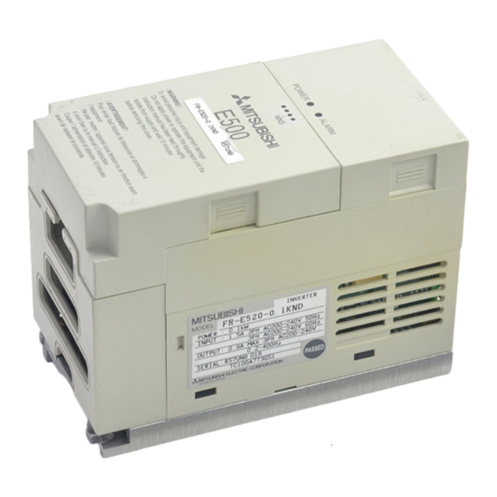
Unpack the inverter and check the capacity plate on the front cover and the rating plate on the inverter side face to ensure that the product agrees with your order and the inverter is intact. 1) Inverter type Capacity plate Rating plate MITSUBISHI Rating plate INVERTER MODEL FR-E520-0.1KND Inverter type... - Page 14 OUTLINE (2) Preparation of instruments and parts required for operation Instruments and parts to be prepared depend on how the inverter is operated. Prepare equipment and parts as necessary. (Refer to page 49.) (3) Installation To operate the inverter with high performance for a long time, install the inverter in a proper place, in the correct direction, with proper clearances.
-
Page 15: Basic Configuration
1.2 Basic Configuration OUTLINE 1.2 Basic Configuration 1.2.1 Basic configuration The following devices are required to operate the inverter. Proper peripheral devices must be selected and correct connections made to ensure proper operation. Incorrect system configuration and connections can cause the inverter to operate improperly, its life to be reduced considerably, and in the worst case, the inverter to be damaged. -
Page 16: Structure
1.3 Structure OUTLINE 1.3 Structure 1.3.1 Appearance and structure (1) Front view POWER lamp (yellow) Accessory cover ALARM lamp (red) Operating status indicator LEDs Rating plate Front cover Capacity plate Wiring cover (2) Without accessory cover and front cover PU connector* POWER lamp (yellow) ALARM lamp (red) Control circuit terminal block... -
Page 17: Removal And Reinstallation Of The
OUTLINE 1.3.3 Removal and reinstallation of the front cover " " " " Removal (For the FR-E520-0.1KND to 3.7KND) The front cover is secured by catches in positions A and B as shown below. Push either A or B in the direction of arrows, and using the other end as a support, pull the front cover toward you to remove. -
Page 18: Removal And Reinstallation Of The Wiring Cover
OUTLINE 1.3.4 Removal and reinstallation of the wiring cover " " " " Removal The wiring cover is fixed by catches in positions 1) and 2). Push either 1) or 2) in the direction of arrows and pull the wiring cover downward to remove. -
Page 19: Removal And Reinstallation Of The Accessory Cover
OUTLINE 1.3.5 Removal and reinstallation of the accessory cover " " " " Removal of the control panel Hold down the portion A indicated by the arrow and lift the right hand side using the portion B indicated by the arrow as a support, and pull out the control panel to the right. -
Page 20: Exploded View
OUTLINE 1.3.6 Exploded view Get other manuals https://www.bkmanuals.com... - Page 21 C H A P T E R 2 CHAPTER 2 INSTALLATIONAND INSTALLATION AND WIRING WIRING This chapter gives information on the basic "installation and wiring" for use of this product. Always read the instructions in this chapter before using the equipment.
-
Page 22: Installation And Wiring
2.1 Installation INSTALLATION AND WIRING 2 INSTALLATION AND WIRING 2.1 Installation 2.1.1 Instructions for installation When mounting any of the FR-E520-0.1KND to 0.75KND, remove the accessory cover, front cover and wiring cover. 1) Handle the unit carefully. The inverter uses plastic parts. Handle it gently to protect it from damage. Also, hold the unit with even strength and do not apply too much strength to the front cover alone. - Page 23 INSTALLATION AND WIRING 6) Avoid places where the inverter is exposed to oil mist, flammable gases, fluff, dust, dirt etc. Install the inverter in a clean place or inside a "totally enclosed" panel which does not accept any suspended matter. 7) Note the cooling method when the inverter is installed in an enclosure.
-
Page 24: Wiring
2.2 Wiring INSTALLATION AND WIRING 2.2 Wiring 2.2.1 Terminal connection diagram " " " " 3-phase 200V power input Motor 3-phase AC power supply Ground Jumper Output stop Remove this jumper when (+)P Reset using the optional power-factor improving DC reactor. Sink input (Note 2) (−)N... - Page 25 INSTALLATION AND WIRING (1) Description of the main circuit terminals Symbol Terminal Name Description Connect to the commercial power supply. Keep these R, S, T AC power input terminals unconnected when using the high power factor converter. U, V, W Inverter output Connect a three-phase squirrel-cage motor.
- Page 26 INSTALLATION AND WIRING (3) DeviceNet signals Terminal Terminal Description Symbol Name V+ (Red) CAN+ (White) DeviceNet ™ SHLD communication Connected with the master station and other slave stations (Bare/nothing) and power to make DeviceNet ™ communication. CAN– (Blue) signals V− (Black) (4) RS-485 communication Name Description...
-
Page 27: Wiring Of The Main Circuit
INSTALLATION AND WIRING 2.2.2 Wiring of the main circuit (1) Wiring instructions 1) It is recommended to use insulation-sleeved solderless terminals for power supply and motor wiring. 2) Power must not be applied to the output terminals (U, V, W) of the inverter. Otherwise the inverter will be damaged. - Page 28 INSTALLATION AND WIRING 6) Connect only the recommended optional brake resistor between the terminals P-PR (+ - PR). Keep terminals P-PR (+ - PR) of 0.1K or 0.2K open. These terminals must not be shorted. 0.1K and 0.2K do not accept the brake resistor. Keep terminals P-PR (+ - PR) open. Also, never short these terminals.
- Page 29 INSTALLATION AND WIRING (2) Terminal block layout of the power circuit FR-E520-0.1KND, 0.2KND, 0.4KND, FR-E520-1.5KND, 2.2KND, 3.7KND 0.75KND N/- P/+ P/+ PR Screw size (M4) Screw size (M4) Screw size (M3.5) Screw size (M4) Screw size (M3.5) FR-E520-5.5KND, 7.5KND Screw size (M5) Screw size (M5)
- Page 30 INSTALLATION AND WIRING (4) Connection of the power supply and motor " " " " Three-phase power input Three-phase power supply 200V Motor Ground Ground terminal No-fuse breaker Ground The power supply cables must be connected Connect the motor to U, V, W. In the above to R, S, T (L ).
-
Page 31: Wiring Of The Control Circuit
INSTALLATION AND WIRING 2.2.3 Wiring of the control circuit (1) Wiring instructions 1) Terminals SD and P24 are common to the I/O signals. Do not connect these common terminals together or do not earth these terminals to the ground. 2) Use shielded or twisted cables for connection to the control circuit terminals and run them away from the main and power circuits (including the 200V relay sequence circuit). - Page 32 INSTALLATION AND WIRING 2) When using bar terminals and solid wires for wiring, their diameters should be 0.9mm maximum. If they are larger, the threads may be damaged during tightening. 3) Loosen the terminal screw and insert the cable into the terminal. 4) Tighten the screw to the specified torque.
- Page 33 INSTALLATION AND WIRING 2) Sink logic type • In this logic, a signal switches on when a current flows out of the corresponding signal input terminal. Terminal SD is common to the contact input signals. Current 3) Source logic type •...
-
Page 34: Devicenet Communication Signal Wiring
INSTALLATION AND WIRING 2.2.4 DeviceNet communication signal wiring (1) Terminal block layout The terminal layout of the inverter's DeviceNet communication signals is as shown below. Terminal screw size: M2.5 CAN+ SHLD CAN- CAUTION The DeviceNet terminal block is hard-wired. It is not removable. (2) Constructing DeviceNet Drop Cable Use the DeviceNet drop cable to connect the inverter to the DeviceNet network. - Page 35 INSTALLATION AND WIRING 1) Strip off the drop cable sheath about 38mm and remove the shield net. In addition to the signal and power wires, there is one drain wire made by twisting the shield net. Drain wire About 38mm 2) Peel off the aluminum tapes which wraps the signal and power wires and strip the insulations about 6mm.
- Page 36 INSTALLATION AND WIRING Pin Out/Functions Pin No. Color Name Signal Type Power cable positive end (V+) White CAN+ Communication data high side (CAN H) Bare SHLD Drain Blue CAN- Communication data low side (CAN L) Black Power cable negative end (V-) —...
- Page 37 INSTALLATION AND WIRING (3) Connection to a Network At this point, the inverter must have been installed correctly with the inverter's node address set (refer to page 47 for node address setting), and the DeviceNet cable connected to the inverter. CAUTION Do not connect cable to the network until told to do so.
- Page 38 INSTALLATION AND WIRING (4) LED Status Indicator The LED Status indicator provides information on the status of operation of the inverter. The status information is shown in the below table. The indicator has five states; Off, Blinking Green, Steady Green, Blinking Red, and Steady Red. After connecting the drop cable to the trunk of the active network, observe the condition of the Status LED.
-
Page 39: Connection To The Pu Connector
Exampl: 5-554720-3, Tyco Electronics Corporation ! Cable : Cable conforming to EIA568 (e.g. 10BASE-T cable) Example: SGLPEV 0.5mm×4P (Twisted pair cable, 4 pairs), MITSUBISHI CABLE INDUSTRIES, LTD. <Maximum wiring length> ! Parameter unit (FR-PU04): 20m (2) For RS-485 communication With the accessory cover disconnected, the PU... - Page 40 : Cable conforming to EIA568 (such as 10BASE-T cable) Example: SGLPEV 0.5mm × 4P (Twisted pair cable, 4 pairs), Mitsubishi Cable Industries, Ltd. (Do not use pins 2) and 8) (P5S).) 3.*Commercially available converter examples Model: FA-T-RS40 Converter Mitsubishi Electric Engineering Co., Ltd. Get other manuals https://www.bkmanuals.com...
- Page 41 INSTALLATION AND WIRING <Wiring methods> 1) Wiring of one RS-485 computer and one inverter Computer Side Terminals Cable connection and signal direction Inverter PU connector Signal name Description 10 BASE-T Cable Receive data Receive data Send data Send data Request to send Request to send (Note 1) Clear to send...
-
Page 42: Connection Of Stand-Alone Option Units
INSTALLATION AND WIRING 2.2.6 Connection of stand-alone option units The inverter accepts a variety of stand-alone option units as required. Incorrect connection will cause inverter damage or an accident. Connect and operate the option unit carefully in accordance with the corresponding option unit manual. (1) Connection of the dedicated external brake resistor (option) (Cannot be connected to 0.1K and 0.2K) Connect a brake resistor across terminals P (+) and PR. - Page 43 INSTALLATION AND WIRING (2) Connection of the BU brake unit (option) Connect the BU brake unit correctly Inverter Motor R (L as shown on the right. Incorrect S (L connection will damage the inverter. T (L Remove jumpers. P (+) N (-) Discharge resistor Constant- voltage...
- Page 44 INSTALLATION AND WIRING (3) Connection of the FR-HC high power factor converter (option unit) When connecting the high power factor converter (FR-HC) to suppress power harmonics, wire as shown below. Wrong connection will damage the high power factor converter and inverter. High power Inverter External box...
-
Page 45: Design Information
INSTALLATION AND WIRING 2.2.7 Design information 1) Provide electrical and mechanical interlocks for MC1 and MC2 which are used for commercial power supply-inverter switch-over. When there is a commercial power supply-inverter switch-over circuit as shown below, the inverter will be damaged by leakage current from the power supply due to arcs generated at the time of switch-over or chattering caused by a sequence error. -
Page 46: Other Wiring
2.3 Other Wiring INSTALLATION AND WIRING 2.3 Other Wiring 2.3.1 Power supply harmonics Power supply harmonics may be generated from the converter section of the inverter, affecting the power supply equipment, power capacitor, etc. Power supply harmonics are different in generation source, frequency band and transmission path from radio frequency (RF) noise and leakage currents. -
Page 47: Japanese Harmonic Suppression Guideline
INSTALLATION AND WIRING 2.3.2 Japanese harmonic suppression guideline Harmonic currents flow from the inverter to a power receiving point via a power transformer. The harmonic suppression guideline was established to protect other consumers from these outgoing harmonic currents. 1) "Harmonic suppression guideline for household appliances and general-purpose products"... - Page 48 INSTALLATION AND WIRING Table 2 Conversion Factors for FR-E500 Series Class Circuit Type Conversion Factor (Ki) K31 = 3.4 Without reactor K32 = 1.8 3-phase bridge With reactor (AC side) K33 = 1.8 (Capacitor-smoothed) With reactor (DC side) With reactors (AC, DC sides) K34 = 1.4...
- Page 49 INSTALLATION AND WIRING Table 5 Rated Capacities and Outgoing Harmonic Currents for Inverter Drive Rated 6.6kV Fundamental Wave Current Converted from 6.6kV Applied Current [A] Equivalent of Rated (No reactor, 100% operation ratio) Motor Fundamental Capacity (kW) 200V Wave Current (kVA) 11th 13th 17th 19th 23rd 25th (mA)
-
Page 50: Inverter-Generated Noise And Reduction Techniques
INSTALLATION AND WIRING 2.3.3 Inverter-generated noise and reduction techniques Some noises enter the inverter causing it to incorrectly operate, and others are radiated by the inverter causing misoperation of peripheral devices. Though the inverter is designed to be insusceptible to noise, it handles low-level signals, so it requires the following basic measures to be taken. - Page 51 INSTALLATION AND WIRING 3) Measures against noises which are radiated by the inverter causing misoperation of peripheral devices. Inverter-generated noises are largely classified into those radiated by the cables connected to the inverter and inverter main circuit (I/O), those electromagnetically and electrostatically inducted to the signal cables of the peripheral devices close to the main circuit power supply, and those transmitted through the power supply cables.
- Page 52 INSTALLATION AND WIRING Noise Path Measures When devices which handle low-level signals and are susceptible to misoperation due to noise (such as instruments, receivers and sensors) are installed near the inverter and their signal cables are contained in the same panel as the inverter or are run near the inverter, the devices may be misoperated by air-propagated noise and the following measures must be taken: (1) Install easily affected devices as far away as possible from the...
- Page 53 INSTALLATION AND WIRING " " " " Data line filter Noise entry can be prevented by providing a data line filter for the detector or other cable. " " " " Data examples By decreasing the carrier frequency, the By using shielded cables as signal cables, noise terminal voltage* can be reduced.
-
Page 54: Leakage Currents And Countermeasures
! By using earth leakage circuit breakers designed for harmonic and surge suppression (e.g. Mitsubishi's Progressive Super Series) in the inverter's own line and other line, operation can be performed with the carrier frequency kept high (with low noise). -
Page 55: Peripheral Devices
INSTALLATION AND WIRING 2.3.5 Peripheral devices (1) Selection of peripheral devices Check the capacity of the motor to be used with the inverter you purchased. Appropriate peripheral devices must be selected according to the capacity. Refer to the following list and prepare appropriate peripheral devices: Power No-Fuse Breaker (NFB) or Earth Leakage Circuit Magnetic Contactor... - Page 56 INSTALLATION AND WIRING " " " " Power factor improving reactor Power Factor Power Factor Inverter Model Improving AC Reactor Improving DC Reactor FR-E520-0.1KND FR-BAL-0.4K (Note) FR-BEL-0.4K (Note) FR-E520-0.2KND FR-BAL-0.4K (Note) FR-BEL-0.4K (Note) FR-E520-0.4KND FR-BAL-0.4K FR-BEL-0.4K FR-E520-0.75KND FR-BAL-0.75K FR-BEL-0.75K FR-E520-1.5KND FR-BAL-1.5K FR-BEL-1.5K FR-E520-2.2KND...
- Page 57 INSTALLATION AND WIRING (2) Selecting the rated sensitivity current for the earth leakage circuit breaker When using the earth leakage circuit breaker with the inverter circuit, select its rated sensitivity current as follows, independently of the PWM carrier frequency: Example of leakage current per 1km in Leakage current example of 3-phase induction motor during commercial cable path during commercial power...
- Page 58 INSTALLATION AND WIRING Progressive Super Series Conventional NV (Type SP, CF, SF,CP) (Type CA, CS, SS) 33 × Leakage current (Ig1) (mA) = 0.17 1000m Leakage current (Ign) (mA) 0 (without noise filter) 33 × Leakage current (Ig2) (mA) = 2.31 1000m Motor leakage 0.18...
-
Page 59: Instructions For Compliance With U.s. And Canadian Electrical Codes
(Note 3) This characteristic curve will be described even under operation of 6Hz or higher when you set the electronic overcurrent 150 180200 Inverter output current (%) protection dedicated to the Mitsubishi (% to rated inverter output current) constant-torque motor. Get other manuals https://www.bkmanuals.com... -
Page 60: Operation/Control
C H A P T E R 3 CHAPTER 3 OPERATION/CONTROL O P E R A T I O N This chapter provides the basic "operation/control" for use of this product. Always read this chapter before using the equipment. 3.1 Inverter Settings............47 Chapter 1 3.2 Configuration ............ -
Page 61: Inverter Settings
3.1 Inverter Settings 3 OPERATION/CONTROL 3.1 Inverter Settings 3.1.1 Node address of the inverter (1) Node address setting Assign a node address for each device (e.g. FR-E520KND) on the DeviceNet network within the range of 0 to 63. To assign the node address, use the node address setting switches SW1 and SW2 (SW1 coresponds to a tens value and SW2 a units value). - Page 62 (2) Changing Node Addresses The state of the node address is sampled once at power on. Changing the address later on will have no effect and the software will keep the number read at power on. The following procedure explains how to change the Node address switches: 1) Turn power to the inverter off.
-
Page 63: Configuration
EDS files. The most recent revision of the FR-E500KND EDS file is available on the Internet as well as a separate item from Mitsubishi Electric. Refer to page 180 for details on how to get this file. -
Page 64: Set Baud Rate
3.2.2 Set baud rate: The baud rate must be consistent throughout the network in order to establish communication and allow configuration via the network. Therefore, this setting is important in the inverter unit configuration. ! Switching power on initializes the FR-E500KND to the communication speed of 125Kbps. - Page 65 (3) Loss of communications In the default polled communication mode, the FR-E500KND will respond to loss of communication based upon the configuration of the EPR bits of Pr. 345 and Pr. 347 as defined on page 125. The default value of these bits is decimal 0. Such loss of polling may occur upon physical disconnection of network cabling, network power loss, failure within the master, etc.
-
Page 66: Operation
3.3 Operation 3.3 Operation The operation modes will be explained as follow. Also parameter definitions for specific DeviceNet parameters are described. 3.3.1 Operation modes PU operation mode Control of the inverter is from the parameter unit (PU). DeviceNet operation mode Control of the inverter is via commands from a DeviceNet master. -
Page 67: Input From Devicenet To Inverter
3.3.3 Input from DeviceNet to inverter Control input commands The FR-E500KND supports STF and STR. Some other Control Input Commands are supported as well. Output Frequency Setting Output frequency setting is possible for the range 0 to 400 Hz in increments of 0.01 Hz. Inverter reset The inverter can be reset via DeviceNet using the ldentity Object reset service. -
Page 68: Operation On Alarm Occurrence
3.3.5 Operation on alarm occurrence The following table shows the behavior of the inverter and network communication operation on alarm occurrence. Operation mode Type of fault Item Net mode PU mode Inverter operation Stop Stop Inverter (Note 3) Network Continue Continue communication Inverter operation Stop (Note 1) - Page 69 C H A P T E R 4 CHAPTER 4 P A R A M E T E R S PARAMETERS This chapter explains the "parameters" of this product. With the factory settings, the inverter is designed to perform simple variable-speed operation. Set necessary parameter values according to the load and operating specifications.
-
Page 70: Parameters
4.1 Parameter List PARAMETERS 4 PARAMETERS 4.1 Parameter List 4.1.1 Parameter list Param- Minimum Custo- Func- Setting Factory Refer eter Name Setting tion Range Setting Number Increments Setting Torque boost (Note 1) 0 to 30% 0.1% Maximum frequency 0 to 120Hz 0.01Hz 120Hz Minimum frequency... - Page 71 PARAMETERS Param- Minimum Custo- Func- Setting Factory Refer eter Name Setting tion Range Setting Number Increments Setting 0 to 400Hz, Frequency jump 1A 0.01Hz 9999 9999 0 to 400Hz, Frequency jump 1B 0.01Hz 9999 9999 0 to 400Hz, Frequency jump 2A 0.01Hz 9999 9999...
- Page 72 PARAMETERS Param- Minimum Custo- Func- Setting Factory Refer eter Name Setting tion Range Setting Number Increments Setting 0, 1, 3, 5, 6, 13, 15, 16, 23, 100, 101, Applied motor (Note 4) 103, 105, 106, 113, 115, 116, 123, PWM frequency selection 0 to 15 Reset selection/ 0 to 3,...
- Page 73 PARAMETERS Param- Minimum Custo- Func- Setting Factory Refer eter Name Setting tion Range Setting Number Increments Setting Stall prevention operation 0 to 31,100 selection User group read selection 0, 1, 10, 11 Parameters set by manufacturer. Do not set. Actual operation hour meter ...
- Page 74 PARAMETERS Param- Minimum Custo- Func- Setting Factory Refer eter Name Setting tion Range Setting Number Increments Setting Soft-PWM setting 0, 1 Cooling fan operation 0, 1 selection 0 to 50%, Rated motor slip 0.01% 9999 9999 Slip compensation 0.01 to 10 s 0.01 s 0.5 s response time...
-
Page 75: List Of Parameters Classified By Purpose Of Use
PARAMETERS 4.1.2 List of parameters classified by purpose of use Set the parameters according to the operating conditions. The following list indicates purpose of use and corresponding parameters. Parameter Numbers Purpose of Use Parameter numbers which must be set Operation mode selection Pr. -
Page 76: Parameters Recommended To Be Set By The User
PARAMETERS Parameter Numbers Purpose of Use Parameter numbers which must be set Display of speed, etc. Pr. 37, Pr. 52 Clearing of inverter's actual operation Pr. 171 time Function write prevention Pr. 77 Reverse rotation prevention Pr. 78 Parameter grouping Pr. -
Page 77: Parameter Function Details
4.2 Parameter Function Details PARAMETERS 4.2 Parameter Function Details 4.2.1 Torque boost (Pr. 0, Pr. 46) Related parameters Pr. 0 "torque boost" Pr. 3 "base frequency" Pr. 46 "second torque boost" Pr. 19 "base frequency voltage" Pr. 71 "applied motor" Pr. -
Page 78: Output Frequency Range (Pr. 1, Pr. 2, Pr. 18)
PARAMETERS 4.2.2 Output frequency range (Pr. 1, Pr. 2, Pr. 18) Related parameters Pr. 1 "maximum frequency" Pr. 13 "starting frequency" Pr. 79 "operation mode selection" Pr. 2 "minimum frequency" Pr. 18 "high-speed maximum frequency" Used to clamp the upper and lower limits of the output frequency. -
Page 79: Base Frequency, Base Frequency Voltage (Pr. 3, Pr. 19, Pr. 47)
! Pr. 47 "Second V/F (base frequency)" is valid when the RT signal is on. (Note 3) ! Use Pr. 19 to set the base voltage (e.g. rated motor voltage). Note: 1. Set 60Hz in Pr. 3 "base frequency" when using a Mitsubishi constant-torque motor. -
Page 80: Multi-Speed Operation (Pr. 4, Pr. 5, Pr. 6, Pr. 24 To Pr. 27, Pr. 232 To Pr. 239)
PARAMETERS " " Multi-speed operation (Pr. 4 to Pr. 6, Pr. 24 to Pr. 27, Pr. 232 to Pr. 239) 4.2.4 Multi-speed operation (Pr. 4, Pr. 5, Pr. 6, Pr. 24 to Pr. 27, Pr. 232 to Pr. 239) Related parameters Pr. -
Page 81: Acceleration/Deceleration Time (Pr. 7, Pr. 8, Pr. 20, Pr. 21, Pr. 44, Pr. 45)
PARAMETERS Note: 1. The multi-speeds can also be set in the PU or DeviceNet operation mode. 2. For 3-speed setting, if two or three speeds are simultaneously selected, priority is given to the frequency setting of the lower signal. 3. Pr. 24 to Pr. 27 and Pr. 232 to Pr. 239 settings have no priority between them. - Page 82 PARAMETERS <Setting> ! Use Pr. 21 to set the acceleration/deceleration time and minimum setting increments: Set value "0" (factory setting)..0 to 3600s (minimum setting increments: 0.1s) Set value "1"......0 to 360s (minimum setting increments: 0.01s) ! Use Pr. 7 and Pr. 44 to set the acceleration time required to reach the frequency set in Pr.
-
Page 83: Electronic Overcurrent Protection (Pr. 9, Pr. 48)
! Setting "0" makes the electronic overcurrent protection (motor protective function) invalid. (The inverter's protective function is valid.) ! When using a Mitsubishi constant-torque motor, first set "1" in Pr. 71 to choose the 100% continuous torque characteristic in the low-speed range. Then, set the rated motor current in Pr. -
Page 84: Dc Injection Brake (Pr. 10 To Pr. 12)
PARAMETERS " " DC dynamic brake (Pr. 10, Pr. 11, Pr. 12) 4.2.7 DC injection brake (Pr. 10 to Pr. 12) Pr. 10 "DC injection brake operation frequency" Pr. 11 "DC injection brake operation time" Pr. 12 "DC injection brake voltage" By setting the DC injection brake voltage (torque), operation time and operation starting frequency, the stopping accuracy of positioning operation, etc. -
Page 85: Starting Frequency (Pr. 13)
PARAMETERS " Starting frequency (Pr. 13) 4.2.8 Starting frequency (Pr. 13) Related parameters Pr. 13 "starting frequency" Pr. 2 "minimum frequency" You can set the starting frequency between 0 and 60Hz. ! Set the starting frequency at which the start signal is switched on. Parameter Factory Setting... -
Page 86: Load Pattern Selection (Pr. 14)
PARAMETERS 4.2.9 Load pattern selection (Pr. 14) " Load pattern selection (Pr. 14) Related parameters Pr. 14 "load pattern selection" Pr. 0 "torque boost" Pr. 46 "second torque boost" Pr. 80 "motor capacity" Pr. 180 to Pr. 183 (input terminal (DeviceNet input) function selection) You can select the optimum output characteristic (V/F characteristic) for the application and load characteristics. -
Page 87: Stall Prevention (Pr. 22, Pr. 23, Pr. 66)
PARAMETERS " " Stall prevention (Pr. 22, Pr. 23, Pr. 66) 4.2.10 Stall prevention (Pr. 22, Pr. 23, Pr. 66) Related parameters Pr. 22 "stall prevention operation level" Pr. 9 "electronic thermal O/L relay" Pr. 48 "second electronic Pr. 23 "stall prevention operation level overcurrent protection"... - Page 88 PARAMETERS <Setting> ! In Pr. 22, set the stall prevention operation level. Normally set it to 150% (factory setting). Set "0" in Pr. 22 to disable the stall prevention operation. ! To reduce the stall prevention operation level in the high-frequency range, set the reduction starting frequency in Pr.
-
Page 89: Acceleration/Deceleration Pattern (Pr. 29)
PARAMETERS " " Acceleration/deceleration pattern (Pr. 29) 4.2.11 Acceleration/deceleration pattern (Pr. 29) Related parameters Pr. 29 "acceleration/deceleration pattern" Pr. 3 "base frequency" Pr. 7 "acceleration time" Pr. 8 "deceleration time" Pr. 20 "acceleration/deceleration reference frequency" Pr. 44 "second Set the acceleration/deceleration pattern. acceleration/deceleration time"... -
Page 90: Regenerative Brake Duty (Pr. 30, Pr. 70)
PARAMETERS " Regenerative brake duty (Pr. 30, Pr. 70) 4.2.12 Regenerative brake duty (Pr. 30, Pr. 70) Pr. 30 "regenerative function selection" Pr. 70 "special regenerative brake duty" ! When making frequent starts/stops, use the optional "brake resistor" to increase the regenerative brake duty. -
Page 91: Frequency Jump (Pr. 31 To Pr. 36)
PARAMETERS " " Frequency jump (Pr. 31 to Pr. 36) 4.2.13 Frequency jump (Pr. 31 to Pr. 36) Pr. 31 "frequency jump 1A" Pr. 32 "frequency jump 1B" Pr. 33 "frequency jump 2A" Pr. 34 "frequency jump 2B" Pr. 35 "frequency jump 3A" Pr. -
Page 92: Speed Display (Pr. 37)
PARAMETERS " " Speed display (Pr. 37) 4.2.14 Speed display (Pr. 37) Related parameter Pr. 37 "speed display" Pr. 52 "PU main display data selection" The unit of the output frequency display of the parameter unit (FR-PU04) can be changed from the frequency to the motor speed or machine speed. Parameter Factory Setting... -
Page 93: Up-To-Frequency Sensitivity (Pr. 41)
PARAMETERS " " Frequency at 5V (10V) input (Pr. 38) " " Up-to-frequency sensitivity (Pr. 41) 4.2.15 Up-to-frequency sensitivity (Pr. 41) Related parameters Pr. 41 "up-to-frequency sensitivity" Pr. 192 "A, B, C terminal (ABC) function selection" The ON range of the up-to-frequency signal (SU) output when the output frequency reaches the running frequency can be adjusted between 0 and ±100% of the running frequency. -
Page 94: Monitor Display (Pr. 52)
PARAMETERS <Setting> Refer to the figure below and set the corresponding parameters: ! When Pr. 43 ≠ 9999, the Pr. 42 setting applies to forward rotation and the Pr. 43 setting applies to reverse rotation. ! Assign the terminal used for FU signal output with Pr. 192 "A, B, C terminal (ABC) function selection". - Page 95 PARAMETERS <Setting> Set Pr. 52 and Pr. 54 in accordance with the following table: Parameter Setting Signal Type Unit Pr. 52 PU main monitor Output 0/100 frequency Output current 0/100 Output voltage 0/100 Alarm display 0/100 Actual operation time When 100 is set in Pr.
-
Page 96: Automatic Restart After Instantaneous Power Failure (Pr. 57, Pr. 58)
PARAMETERS " " Monitoring reference (Pr. 55, Pr. 56) " " Automatic restart after instantaneous power failure (Pr. 57, Pr. 58) 4.2.18 Automatic restart after instantaneous power failure (Pr. 57, Pr. 58) Pr. 57 "restart coasting time" Pr. 58 "restart cushion time" ! You can restart the inverter without stopping the motor (with the motor coasting) when power is restored after an instantaneous power failure. -
Page 97: Shortest Acceleration/Deceleration Mode (Pr. 60 To Pr. 63)
PARAMETERS Note: 1. Automatic restart after instantaneous power failure uses a reduced-voltage starting system in which the output voltage is raised gradually with the preset frequency unchanged, independently of the coasting speed of the motor. As in the FR-A024/044, a motor coasting speed detection system (speed search system) is not used but the output frequency before an instantaneous power failure is output. - Page 98 PARAMETERS < Setting> Automatically Pr. 60 Operation Description Setting Mode Parameters Ordinary operation mode Set to accelerate/decelerate the motor in the shortest time. The inverter makes acceleration/deceleration in the shortest time using its full capabilities. During deceleration, an insufficient brake capability may Shortest cause the regenerative overvoltage alarm 1, 2, 11,...
-
Page 99: Retry Function (Pr. 65, Pr. 67 To Pr. 69)
PARAMETERS " " Retry function (Pr. 65, Pr. 67, Pr. 68, Pr. 69) 4.2.20 Retry function (Pr. 65, Pr. 67 to Pr. 69) Pr. 65 "retry selection" Pr. 67 "number of retries at alarm occurrence" Pr. 68 "retry waiting time" Pr. - Page 100 PARAMETERS Use Pr. 67 to set the number of retries at alarm occurrence. Pr. 67 Setting Number of Retries Alarm Signal Output Retry is not made. 1 to 10 1 to 10 times Not output. 101 to 110 1 to 10 times Output.
-
Page 101: Applied Motor (Pr. 71)
Pr. 96 "auto-tuning setting/status" Set the motor used. ! When using the Mitsubishi constant-torque motor, set "1" in Pr. 71 for either V/F control or general-purpose magnetic flux vector control. The electronic overcurrent protection is set to the thermal characteristic of the constant-torque motor. -
Page 102: Pwm Carrier Frequency (Pr. 72, Pr. 240)
PARAMETERS " Applied motor (Pr. 71) " " PWM carrier frequency (Pr. 72, Pr. 240) 4.2.22 PWM carrier frequency (Pr. 72, Pr. 240) Pr. 72 "PWM frequency selection" Pr. 240 "Soft-PWM setting" You can change the motor tone. ! By parameter setting, you can select Soft-PWM control which changes the motor tone. -
Page 103: Reset Selection/Disconnected Pu Detection/Pu Stop Selection (Pr. 75)
PARAMETERS " " Voltage input (Pr. 73) " Reset selection/disconnected PU detection/PU stop selection (Pr. 75) 4.2.23 Reset selection/disconnected PU detection/PU stop selection (Pr. 75) Pr. 75 "reset selection/disconnected PU detection/PU stop selection" You can select the reset selection, disconnected PU (FR-PU04) detection function and PU stop selection function. - Page 104 PARAMETERS STOP How to make a restart after a stop by the key on the PU RESET Parameter unit (FR-PU04) 1) After completion of deceleration to a stop, switch off the STF or STR signal. 2) Press the key. 3) Switch on the STF or STR signal. Time Parameter unit (FR-PU04)
-
Page 105: Parameter Write Inhibit Selection (Pr. 77)
PARAMETERS 4.2.24 Parameter write inhibit selection (Pr. 77) Related parameters Pr. 77 "parameter write disable selection" Pr. 79 "operation mode selection" You can select between write-enable and disable for parameters. This function is used to prevent parameter values from being rewritten by incorrect operation. Parameter Factory Setting Range... -
Page 106: Operation Mode Selection (Pr. 79)
PARAMETERS " " Operation mode selection (Pr. 79) 4.2.26 Operation mode selection (Pr. 79) Related parameters Pr. 79 "operation mode selection" Pr. 4 to Pr. 6, Pr. 24 to Pr. 27, Pr. 232 to Pr. 239 (multi-speed operation) Used to select the operation mode of the inverter. Pr. -
Page 107: General-Purpose Magnetic Flux Vector Control Selection (Pr. 80)
General- purpose 0.1 to 7.5 Set the motor capacity applied. magnetic flux vector control ! When using Mitsubishi's constant-torque motor (SF-JRCA), set "1" in Pr. 71. (When using the SF-JRC, perform the offline auto tuning .) Get other manuals https://www.bkmanuals.com... -
Page 108: Offline Auto Tuning Function (Pr. 82 To Pr. 84, Pr. 90, Pr. 96)
" The Mitsubishi standard motor (SF-JR0.4kW or more) or Mitsubishi constant-torque motor (By SF-JRCA 200V class and 4-pole motor of 0.4kW to 7.5kW) allows general-purpose magnetic flux vector control operation to be performed without using the offline auto tuning function. - Page 109 ! Standard motor ..............Pr. 71 = "3" or "103" ! Constant-torque motor............Pr. 71 = "13" or "113" ! Mitsubishi standard motor SF-JR 4 poles (1.5kW or less). Pr. 71 = "23" or "123" Note: Pr. 83 and Pr. 84 are only displayed when the general-purpose magnetic flux vector control is selected.
- Page 110 Setting Description Number 0 to 500A Set the rated motor current (A). 0, 100 Thermal characteristics suitable for standard motor Thermal characteristics suitable for Mitsubishi's constant- 1, 101 torque motor 3, 103 Standard motor 13, 113 Constant-torque motor Select "offline auto tuning setting"...
- Page 111 PARAMETERS (3) Monitoring the offline tuning status ! For confirmation on the DeviceNet master unit, check the Pr. 96 setting. 1: setting, 2: tuning in progress, 3: completion, 8: forced end, 9: error-activated end ! When the parameter unit (FR-PU04) is used, the Pr. 96 value is displayed during tuning on the main monitor as shown below: ! Parameter unit (FR-PU04) main monitor (For inverter trip)
- Page 112 PARAMETERS 4) Error display definitions Error Display Error Cause Remedy Inverter trip Make setting again. Increase Current limit (stall prevention) function was acceleration/deceleration time. activated. Set "1" in Pr. 156. Converter output voltage reached 75% of Check for fluctuation of power rated value.
- Page 113 PARAMETERS <Setting the motor constant as desired> " To set the motor constant without using the offline auto tuning data <Operating procedure> 1. Set any of the following values in Pr. 71: Star Connection Delta Connection Motor Motor Standard motor 5 or 105 6 or 106 Setting...
-
Page 114: Computer Link Operation (Pr. 117 To Pr. 124)
PARAMETERS " Computer link operation (Pr. 117 to Pr. 124) 4.2.29 Computer link operation (Pr. 117 to Pr. 124) Pr. 117 "station number" Pr. 118 "communication speed" Pr. 119 "stop bit length" Pr. 120 "parity check presence/absence" Pr. 121 "number of communication retries" Pr. - Page 115 PARAMETERS <Setting> To make communication between the personal computer and inverter, the communication specifications must be set to the inverter initially. If initial setting is not made or there is a setting fault, data transfer cannot be made. Note: After making the initial setting of the parameters, always reset the inverter. After have changed...
- Page 116 PARAMETERS <Computer programming> (1) Communication protocol Data communication between the computer and inverter is performed using the following procedure: Data read Computer ↓ (Data flow) Inverter Time Inverter ↓ (Data flow) Data write Computer *1. If a data error is detected and a retry must be made, execute retry operation with the user program.
- Page 117 PARAMETERS (3) Data format Data used is hexadecimal. Data is automatically transferred in ASCII between the computer and inverter. 1) Data format types (1) Communication request data from computer to inverter [Data write] Inverter Instruction Format A station Data check code number ←Number of characters...
- Page 118 PARAMETERS 3) Reply data from inverter to computer during data read [No data error detected] [Data error detected] Inverter Read Format E station check data number Format F 10 11 Inverter Inverter Read Error Format E' station station code data check number number...
- Page 119 PARAMETERS 5) Waiting time Specify the waiting time between the receipt of data at the inverter from the computer and the transmission of reply data. Set the waiting time in accordance with the response time of the computer between 0 and 150ms in 10ms increments (e.g.
- Page 120 PARAMETERS 7) Sum check code The sum check code is 2-digit ASCII (hexadecimal) representing the lower 1 byte (8 bits) of the sum (binary) derived from the checked ASCII data. (Example 1) Station Instruction Computer → inverter check Data number code code ←Binary code...
- Page 121 PARAMETERS CAUTION When the inverter's permissible communication time interval is not set, interlocks are provided to disable operation to prevent hazardous conditions. Always set the communication check time interval before starting operation. Data communication is not started automatically but is made only once when the computer provides a communication request.
- Page 122 PARAMETERS <Setting items and set data> After completion of parameter settings, set the instruction codes and data then start communication from the computer to allow various types of operation control and monitoring. Number of Data Instruction Digits Item Description (Data Code code FF=1)
- Page 123 PARAMETERS Number of Data Instruction Digits Item Description (Data Code code FF=1) b0: Inverter running (RUN) b1: Forward rotation 0 0 0 0 0 0 b2: Reverse rotation (For example 1) Inverter status b3: Up to frequency (SU) 2 digits [Example 1] H02 ...
- Page 124 PARAMETERS Number of Data Instruction Digits Item Description (Data Code code FF=1) H00 to H6C and H80 to HEC parameter values are changed. Read Link H00: Pr. 0 to Pr. 96 values are accessible. parameter H01: Pr. 117 to Pr. 156 values are accessible. 2 digits expansion H02: Pr.
- Page 125 PARAMETERS <Error Code List> The corresponding error code in the following list is displayed if an error is detected in any communication request data from the computer: Error Item Definition Inverter Operation Code number errors consecutively Computer NAK detected in communication request data error from the computer is greater than allowed number of retries.
- Page 126 PARAMETERS (5) Communication specifications for RS-485 communication Operation Mode Operation Communication Item Location Operation from PU Connector Run command (start) Enable Running frequency setting Enable Monitoring Enable Computer user program via Parameter write Enable (*2) PU connector Parameter read Enable Inverter reset Enable Stop command (*1)
-
Page 127: Settings For Connection Of Fr-Pu04 (Pr. 145, Pr. 990, Pr. 991)
PARAMETERS " " PID control (Pr. 128 to Pr. 134) 4.2.30 Settings for connection of FR-PU04 (Pr. 145, Pr. 990, Pr. 991) Pr. 145 "Parameter unit display language selection" Pr. 990 "Buzzer beep control" Pr. 991 "LCD contrast" ! ! ! ! All of the below parameters are only applicable when using the FR-PU04 parameter unit. -
Page 128: Output Current Detection Function (Pr. 150, Pr. 151)
PARAMETERS " Output current detection function (Pr. 150 to Pr. 151) 4.2.31 Output current detection function (Pr. 150, Pr. 151) Related parameters Pr. 150 "output current detection level" Pr. 192 "A, B, C terminal (ABC) function Pr. 151 "output current detection period" selection"... -
Page 129: Zero Current Detection (Pr. 152, Pr. 153)
PARAMETERS " " Zero current detection (Pr. 152, Pr. 153) 4.2.32 Zero current detection (Pr. 152, Pr. 153) Related parameters Pr. 152 "zero current detection level" Pr. 192 "A, B, C terminal function (ABC) selection" Pr. 153 "zero current detection period" When the inverter's output current falls to "0", torque will not be generated. -
Page 130: Stall Prevention Function And Current Limit Function (Pr. 156)
PARAMETERS CAUTION The zero current detection level setting should not be too high, and the zero current detection time setting should not be too long. Otherwise, the detection signal may not be output when torque is not generated at a low output current. - Page 131 PARAMETERS <Setting> Refer to the following tables and set the parameter as required. Stall Prevention Stall Prevention OL Signal OL Signal Operation Operation Output Output Fast- Fast- Selection Selection ': Activated ': Activated Response Response Operation Operation " " Current Current : Not activated : Not activated...
-
Page 132: User Group Selection (Pr. 160, Pr. 173 To Pr. 176)
PARAMETERS " User group selection (Pr. 160, Pr. 173 to Pr. 176) 4.2.34 User group selection (Pr. 160, Pr. 173 to Pr. 176) Pr. 160 "user group read selection" Pr. 173 "user group 1 registration" Pr. 174 "user group 1 deletion" Pr. -
Page 133: Actual Operation Hour Meter Clear (Pr. 171)
PARAMETERS 4.2.35 Actual operation hour meter clear (Pr. 171) Related parameter Pr. 171 "actual operation hour meter Pr. 52 "PU main display data clear" selection" You can clear the monitor (actual operation hour) value which is selected when Pr. 52 is "23". - Page 134 PARAMETERS " " Actual operation hour meter clear (Pr. 171) <Setting> Refer to the following list and set the parameters. Signal Related Setting Function Name Parameters Pr. 4 to Pr. 6 Low-speed operation command Pr. 24 to Pr. 27 Pr. 232 to Pr. 239 Pr.
-
Page 135: Output Terminal (Devicenet Input) Function Selection (Pr. 190 To Pr. 192)
PARAMETERS " Output terminal function selection (Pr. 190 to Pr. 192) 4.2.37 Output terminal (DeviceNet input) function selection (Pr. 190 to Pr. 192) Pr. 190 "(RUN) function selection" Pr. 191 "(FU) function selection" Pr. 192 "A, B, C terminal (ABC) function selection" You can change the functions of the contact output terminals (DeviceNet input). -
Page 136: Cooling Fan Operation Selection (Pr. 244)
PARAMETERS Pr. 232 to Pr. 239 & & & & Refer to Pr. 4. Pr. 240 & & & & Refer to Pr. 72. " Cooling fan operation selection ( " Pr. 244) 4.2.38 Cooling fan operation selection (Pr. 244) Pr. -
Page 137: Slip Compensation (Pr. 245 To Pr. 247)
PARAMETERS " " Slip compensation (Pr. 245 to Pr. 247) 4.2.39 Slip compensation (Pr. 245 to Pr. 247) Pr. 245 "rated motor slip" Pr. 246 "slip compensation response time constant" Pr. 247 "constant-output region slip compensation selection" The inverter output current may be used to assume motor slip to keep the motor speed constant. -
Page 138: Ground Fault Detection At Start (Pr. 249)
PARAMETERS " " Ground fault detection at start (Pr. 249) 4.2.40 Ground fault detection at start (Pr. 249) Pr. 249 "ground fault detection at start" You can select whether ground fault detection at start is made or not. Ground fault detection is made only immediately after the start signal is input to the inverter. - Page 139 PARAMETERS (1)Pr. 250 = "9999" When the start signal switches off, the motor is decelerated to a stop. Start signal Output frequency Decelerated when start signal switches off. (Hz) Deceleration time (time set in Pr. 8, etc.) DC brake Time (2)Pr.
-
Page 140: Devicenet Specific Parameters (Pr. 345 To Pr. 348)
PARAMETERS 4.2.42 DeviceNet specific parameters (Pr. 345 to Pr. 348) Pr. 345 "DeviceNet Address Startup Data (Lower byte)" Pr. 346 "DeviceNet Baudrate Startup Data (Lower byte)" Pr. 347 "DeviceNet Address Startup (Higher byte)" Pr. 348 "DeviceNet Baudrate Startup Data (Higher byte)" Pr. - Page 141 PARAMETERS Definitions of each registration Default Name Description Definition setting Watch dog DeviceNet connection object 0 = Transition to timeout timeout operation (Class code 0x05) 1 = Automatic delete (WDA) (Note) Instance 2 attribute 12 2 = Automatic reset Supports the control management object.
- Page 142 C H A P T E R 5 CHAPTER 5 PROTECTIVE PROTECTIVE FUNCTIONS FUNCTIONS This chapter explains the "protective functions" of this product. Always read the instructions before using the equipment. 5.1 Errors (Alarms) ............127 5.2 Troubleshooting ............135 Chapter 1 5.3 Precautions for Maintenance and Inspection ..
-
Page 143: Protective Functions
5.1 Errors (Alarms) PROTECTIVE FUNCTIONS 5 PROTECTIVE FUNCTIONS 5.1 Errors (Alarms) If any fault has occurred in the inverter, the corresponding protective function is activated to bring the inverter to an alarm stop and automatically give the corresponding error (alarm) indication on the PU display. If your fault does not correspond to any of the following errors or if you have any other problem, please contact your sales representative. -
Page 144: Error (Alarm) Definitions
PROTECTIVE FUNCTIONS 5.1.2 Error (alarm) definitions (1) Major faults When the protective function is activated, the inverter output is shut off and the alarm is output. FR-PU04 Indication OC During Acc Overcurrent shut-off during acceleration Name When the inverter output current reaches or exceeds approximately Description 200% of the rated current during acceleration, the protective circuit is activated to stop the inverter output. - Page 145 PROTECTIVE FUNCTIONS FR-PU04 Indication Stedy Spd OV Regenerative overvoltage shut-off during constant speed Name If regenerative energy causes the inverter's internal main circuit DC voltage to reach or exceed the specified value, the protective circuit Description is activated to stop the inverter output. It may also be activated by a surge voltage generated in the power supply system.
- Page 146 PROTECTIVE FUNCTIONS FR-PU04 Indication H/Sink O/Temp Fin overheat Name If the cooling fin overheats, the overheat sensor is actuated to stop Description the inverter output. • Check for too high ambient temperature. Check point • Check for cooling fin clogging. Corrective action Set the ambient temperature to within the specifications.
- Page 147 PROTECTIVE FUNCTIONS FR-PU04 Indication Stll Prev STP Stall prevention Name The running frequency has fallen to 0 by stall prevention activated. Description (OL while stall prevention is being activated.) Check point Check the motor for use under overload. Corrective action Reduce the load weight.
- Page 148 PROTECTIVE FUNCTIONS FR-PU04 Indication CPU Fault CPU error Name If the arithmetic operation of the built-in CPU does not end within a Description predetermined period, the inverter self-determines it as an alarm and stops the output. Check point Corrective action Please contact your sales representative.
- Page 149 PROTECTIVE FUNCTIONS (3) Warnings FR-PU04 Indication Stall prevention (overcurrent) Name If a current of more than 150% (Note 4) of the During rated inverter current flows in the motor, this acceleration function stops the increase in frequency until the overload current reduces to prevent the inverter from resulting in overcurrent shut-off.
-
Page 150: To Know The Operating Status At The Occurrence Of Alarm
PROTECTIVE FUNCTIONS 5.1.3 To know the operating status at the occurrence of alarm If any fault has occurred in the inverter, the corresponding protective function is activated to bring the inverter to an alarm stop and automatically give the corresponding error (alarm) indication on the PU display. If your fault does not correspond to any of the following errors or if you have any other problem, please contact your sales representative. -
Page 151: Troubleshooting
5.2 Troubleshooting PROTECTIVE FUNCTIONS 5.2 Troubleshooting POINT:Check the corresponding areas. If the cause is still unknown, it is recommended to initialize the parameters (return to factory settings), re-set the required parameter values, and check again. 5.2.1 Motor remains stopped 1) Check the main circuit Check that a proper power supply voltage is applied (POWER lamp is lit). -
Page 152: Speed Greatly Differs From The Setting
PROTECTIVE FUNCTIONS 5.2.3 Speed greatly differs from the setting Check that the frequency setting signal is correct. (Measure the input signal level.) Check that the following parameter settings are correct (Pr. 1, Pr. 2, Pr. 19, Pr. 245). Check that the input signal lines are not affected by external noise. (Use shielded cables) Check that the load is not too heavy. -
Page 153: The Operation Mode Does Not Change To The Devicenet Operation Mode
PROTECTIVE FUNCTIONS 5.2.8 The operation mode does not change to the DeviceNet operation mode Check that the inverter and cable are correctly connected. (Is there any contact failure, disconnection, etc.?) Check that the node address setting switch is correctly set. (Does the setting match the program? Is the node address duplicated or outside the range?) Check that the operation mode changeover program has been executed. -
Page 154: How To Check For Errors Using The Operation Status Indicator Led
If a fault occurs and the inverter fails to operate properly, locate the cause of the fault and take proper corrective action by referring to page 135. If the corresponding information is not found the inverter may have a problem, or the component parts maybe damaged, contact your local Mitsubishi sales representative. Get other manuals https://www.bkmanuals.com... -
Page 155: Inspecting Display On Parameter Unit And Status Led
PROTECTIVE FUNCTIONS 5.2.12 Inspecting display on parameter unit and status LED In response to the occurrence of a fault, the display unit of the inverter automatically displays the code of the detected fault and MNS Status LED shows the status of the detected fault. -
Page 156: Precautions For Maintenance And Inspection
5.3 Precautions for Maintenance and Inspection PROTECTIVE FUNCTIONS 5.3 Precautions for Maintenance and Inspection The transistorized inverter is a static unit mainly consisting of semiconductor devices. Daily inspection must be performed to prevent any fault from occurring due to adverse influence by the operating environment, such as temperature, humidity, dust, dirt and vibration, changes in the parts with time, service life, and other factors. -
Page 157: Insulation Resistance Test Using Megger
PROTECTIVE FUNCTIONS 5.3.4 Insulation resistance test using megger 1) Before performing the insulation resistance test using a megger on the external circuit, disconnect the cables from all terminals of the inverter so that the test voltage is not applied to the inverter. 2) For the continuity test of the control circuit, use a meter (high resistance range) and do not use the megger or buzzer. -
Page 158: Daily And Periodic Inspection
PROTECTIVE FUNCTIONS 5.3.6 Daily and periodic inspection Interval Periodic* Inspection Description Method Criterion Instrument Item Ambient temperature: -10°C to +50°C, Thermo- Check ambient Surrounding non-freezing. meter, temperature, humidity, Refer to page 9. environment Ambient hygrometer, dust, dirt, etc. humidity: 90% recorder or less, non- condensing. - Page 159 ' Disconnect cables Check with megger 5MΩ or more. 500V Insulation (across terminals and from U, V, W, megger resistance ground terminal). including motor cables. * For periodic inspection, contact you nearest Mitsubishi sales representative. Get other manuals https://www.bkmanuals.com...
- Page 160 PROTECTIVE FUNCTIONS " " " " Checking the inverter and converter modules <Preparation> (1)Disconnect the external power supply cables (R, S, T (L )) and motor cables (U, V, W). (2)Prepare a meter. (Use 100Ω range.) <Checking method> Change the polarity of the meter alternately at the inverter terminals R (L ), S (L T (L ), U, V, W, P (+) and N (−), and check for continuity.
-
Page 161: Replacement Of Parts
5 years control board (as required). Note: For part replacement, contact the nearest Mitsubishi FA center. (1) Cooling fan The cooling fan cools heat-generating parts such as the main circuit semiconductor devices. The life of the cooling fan bearing is usually 10,000 to 35,000 hours. Hence, the cooling fan must be changed every 2 to 3 years if the inverter is run continuously. - Page 162 PROTECTIVE FUNCTIONS " " " " Reinstallation 1) After confirming the orientation of the fan, reinstall the fan to the cover so that the arrow on the left of "AIR FLOW" faces in AIR FLOW the opposite direction of the fan cover. Note: If the air flow is set in the wrong direction, the inverter life can be shorter.
-
Page 163: Measurement Of Main Circuit Voltages, Currents And Powers
PROTECTIVE FUNCTIONS 5.3.8 Measurement of main circuit voltages, currents and powers " " " " Measurement of voltages and currents Since the voltages and currents on the inverter power supply and output sides include harmonics, accurate measurement depends on the instruments used and circuits measured. When instruments for commercial frequency are used for measurement, measure the following circuits using the instruments given on the next page. - Page 164 PROTECTIVE FUNCTIONS Measuring Points and Instruments Remarks Item Measuring Point Measuring Instrument (Reference Measured Value) Power supply Is the commercial power supply within Across R-S (L ), S-T (L Moving-iron type AC voltage permissible variation of AC voltage ) and T-R (L voltmeter (V1) (Refer to page 149)
-
Page 165: Specifications
CHAPTER 6 SPECIFICATIONS This chapter provides the "specifications" of this product. Always read the instructions before using the equipment 6.1 Standard Specifications .......... 149 Chapter 1 Chapter 2 Chapter 3 Chapter 4 Chapter 5 Chapter 6 Get other manuals https://www.bkmanuals.com... -
Page 166: Standard Specifications
Approximate weight (kg) Note: 1. The applicable motor capacity indicated is the maximum capacity applicable when a Mitsubishi 4-pole standard motor is used. 2. The rated output capacity indicated assumes that the output voltage is 230V. 3. The overload capacity indicated in % is the ratio of the overload current to the inverter's rated current. -
Page 167: Common Specifications
SPECIFICATIONS 6.1.2 Common specifications Soft-PWM control/high carrier frequency PWM control can be selected. Control system V/F control or general-purpose magnetic flux vector control can be selected. Output frequency range 0.2 to 400Hz (starting frequency variable between 0 and 60Hz) Frequency setting Digital input 0.01Hz (less than 100Hz), 0.1Hz (100Hz or more) - Page 168 SPECIFICATIONS Maximum/minimum frequency setting, frequency jump operation, external thermal relay input selection, automatic restart operation after Operation functions instantaneous power failure, forward/reverse rotation prevention, slip compensation, operation mode selection, offline auto tuning function DeviceNet operation. 1 contact output (230VAC 0.3A, 30VDC 0.3A) can be selected from inverter running, up to frequency, frequency detection, overload alarm, Operating status zero current detection, output current detection, operation ready, minor...
-
Page 169: Outline Dimension Drawings
SPECIFICATIONS 6.1.3 Outline dimension drawings " " " " FR-E520-0.1KND, 0.2KND, 0.4KND, 0.75KND φ5 hole 30.6 Capacity FR-E520-0.1KND 95.6 FR-E520-0.2KND 95.6 FR-E520-0.4KND 127.6 Wiring holes FR-E520-0.75KND 147.6 Note: FR-E520-0.75KND is provided with cooling fan. (Unit: mm) Get other manuals https://www.bkmanuals.com... - Page 170 SPECIFICATIONS " " " " FR-E520-1.5KND, 2.2KND 2-φ5 hole 30.6 150.6 Wiring holes Cooling fan ×1 (Unit: mm) Get other manuals https://www.bkmanuals.com...
- Page 171 SPECIFICATIONS " " " " FR-E520-3.7KND 2-φ5 hole 30.6 82.5 19.5 157.6 55.5 114.5 Wiring holes Cooling fan ×1 (Unit: mm) Get other manuals https://www.bkmanuals.com...
- Page 172 SPECIFICATIONS " " " " FR-E520-5.5KND, 7.5KND 2-φ6 hole 112.5 57.5 19.6 189.6 Wiring holes Cooling fans × 2 (Unit: mm) Get other manuals https://www.bkmanuals.com...
-
Page 173: Devicenet Specifications
SPECIFICATIONS 6.1.4 DeviceNet specifications • Communication power: supplied by DeviceNet 1) Power supply power supply, 11 to 28 V with a 10 A capacity • Conforms to ODVA DeviceNet Specification, 2) Standard supports UCMM • DeviceNet (linear bus with drop lines) 3) Network topology •... -
Page 174: Appendix
Always read the instructions before using the equipment. Appendix 1 Object Map ..........157 Appendix 2 Electronic Data Sheets (EDS files)..... 180 Appendix 3 FR-E500 Series DeviceNet Type Parameter Data.......... 181 Appendix 4 Data Code List ........... 185 Get other manuals https://www.bkmanuals.com... -
Page 175: Appendix 1 Object Map
APPENDIX 1 Object Map APPENDIX APPENDIX 1 Object Map This section describes the DeviceNet object definitions of the FR-E500KND. For details of the definitions, please consult the DeviceNet documentation available from ODVA. In the following tables, Get and Set mean: Get: Read from inverter Set: Write to inverter 1. - Page 176 2. Class 0x03 - DeviceNet Object (1) Class 0x03 Attributes - Instance 0 Note: Not applicable to the FR-E500KND. (2) Class 0x03 Services - Instance 0 Note: Not applicable to the FR-E500KND. (3) Class 0x03 Instance Attributes - Instance 1 Access Attribute Value...
- Page 177 3. Class 0x04 - Assembly Object (1) Class 0x04 - Output Instance 20 Instance Byte Bit 7 Bit 6 Bit 5 Bit 4 Bit 3 Bit 2 Bit 1 Bit 0 0x14 Fault − − − − − − Reset −...
- Page 178 The Output Instance 126 bytes operate in the following manner: Byte Bit 7 - If Write Parameter=1, the Parameter Write Data is written to the parameter and the rest of the parameter is ignored. Bit 7 - If Write Parameter=0, the Speed Ref in RPM is set, and the rest of the command byte is executed.
- Page 179 (6) Class 0x04 - Input Instance 176 Instance Byte Bit 7 Bit 6 Bit 5 Bit 4 Bit 3 Bit 2 Bit 1 Bit 0 0xB0 Control At Ref Run (2) Run (1) − From From Ready Faulted Speed Speed Actual (Low Byte) Speed Actual (High Byte) Parameter Read (Low Byte) Parameter Read (High Byte)
- Page 180 (7) Class 0x04 - Input Instance 150 Instance Byte Bit 7 Bit 6 Bit 5 Bit 4 Bit 3 Bit 2 Bit 1 Bit 0 0x96 Running Running − − − Faulted 0x00 Actual Speed (Low Byte) Actual Speed (High Byte) Output Current (Low Byte) Output Current (High Byte) Error Factor...
- Page 181 (8) Class 0x04 - Output Instance 100 Output Byte Bit 7 Bit 6 Bit 5 Bit 4 Bit 3 Bit 2 Bit 1 Bit 0 Instance Write Fault − 0x64 Param Ctrl Reset 0x00 Speed Reference (Low Byte) Speed Reference (High Byte) Acceleration Time (Low Byte) Acceleration Time (High Byte) Deceleration Time (Low Byte)
- Page 182 4. Class 0x05 - DeviceNet Connection Object The FR-E500KND supports only Polled I/O and Explicit Messaging. It does not support Bit-Strobed I/O. (1) Class 0x05 Attributes - Instance 0 Note: Not applicable to the FR-E500KND. (2) Class 0x05 Services - Instance 0 Note: Not applicable to the FR-E500KND.
- Page 183 (4) Class 0x05 Instance Attributes Instance 2 - Polled I/O Access Attribute Value State 0 to 5 Instance Type 0 to 1 Transport Trigger Class 0x83 Produced Connection ID 0 to 0x7F0 Consumed Connection ID 0 to 0x7F0 Initial Comm Characteristics 0x01 Produced Connection Size Consumed Connection Size...
- Page 184 (6) Class 0x05 Instance Attributes Instance 4 - Explicit Messaging Access Attribute Value State 0 to 5 Instance Type 0 to 1 Transport Trigger Class 0x83 Produced Connection ID 0 to 0x7F0 Consumed Connection ID 0 to 0x7F0 Initial Comm. Characteristics 0x33 Produced Connection Size Consumed Connection Size...
- Page 185 (8) Class 0x05 Instance Attributes Instance 6 - Explicit Messaging Access Attribute Value State 0 to 5 Instance Type 0 to 1 Transport Trigger Class 0x83 Produced Connection ID 0 to 0x7F0 Consumed Connection ID 0 to 0x7F0 Initial Comm Characteristics 0x33 Produced Connection Size Consumed Connection Size...
- Page 186 5. Class 0x28 - Motor Data Object (1) Class 0x28 Attributes - Instance 0 Note: Not applicable to the FR-E500KND. (2) Class 0x28 Services - Instance 0 Note: Not applicable to the FR-E500KND. (3) Class 0x28 Instance Attributes Instance 1 Access Attribute Value...
- Page 187 6. Class 0x29 - Control Supervisor Object (1) Class 0x29 Attributes - Instance 0 Note: Not applicable to the FR-E500KND. (2) Class 0x29 Services Note: Not applicable to the FR-E500KND. (3) Class 0x29 Instance Attributes Instance 1 Access Attribute Value Forward Rotation Get/Set 0 to 1...
- Page 188 7. Class 0x2A - AC Drive Object (1) Class 0x2A Attributes - Instance 0 Note: Not applicable to the FR-E500KND. (2) Class 0x2A Services Note: Not applicable to the FR-E500KND. (3) Class 0x2A Instance Attributes Instance 1 AC Profile Compatibles Access Attribute Value...
- Page 189 The following variables and parameters are specific to the FR-E500KND. FR-E500KND System Environment Variables Access Attribute Value Inverter reset Parameter Clear 0x965A Parameter All Clear 0x99AA Parameter Clear (Ex Com Pr) 0x5A96 Parameter All Clear (Ex Com Pr) 0xAA99 Get/Set Running Frequency (RAM) (Note) 30.00Hz 30.00Hz...
- Page 190 Alarm Code List Code Definition Code Definition Code Definition 0x10 0x80 0xF5 0x11 0x81 0xF6 0x12 0x90 0xF7 0x20 0xB0 0xF8 0x21 0xB1 0xF9 0x22 0xB2 0xFA 0x30 0xC0 0xFB 0x31 0xF0 0xFC 0x40 0xF1 0xFD 0x41 0xF2 0xFE 0x60 0xF3 0xFF 0x70...
- Page 191 8. Class 0x66 - E500 Extended Object 1 (1) Class 0x66 Attributes - Instance 0 Note: Not applicable to the FR-E500KND. (2) Class 0x66 Services Note: Not applicable to the FR-E500KND. (3) Class 0x66 Instance Attributes Instance 1 Parameters (Pr. 0 = No.10) Access Attribute Default Setting...
- Page 192 Access Attribute Default Setting Get/Set Pr. 29 Acceleration/Deceleration Pattern Get/Set Pr. 30 Regenerative Function Selection Get/Set Pr. 31 Frequency Jump 1A (Note 3) Get/Set Pr. 32 Frequency Jump 1B (Note 3) Get/Set Pr. 33 Frequency Jump 2A (Note 3) Get/Set Pr.
- Page 193 Access Attribute Default Setting Pr. 79 Operation Mode Selection Get/Set Pr. 80 Motor Capacity (Note 3) Get/Set Pr. 82 Motor Exciting Current (Note 3) Get/Set Pr. 83 Rated Motor Voltage (Note 2) Get/Set Pr. 84 Rated Motor Frequency 60.00Hz Get/Set Pr.
- Page 194 Access Attribute Default Setting Get/Set Pr. 234 Multi-Speed Setting (Speed 10) (Note 3) Get/Set Pr. 235 Multi-Speed Setting (Speed 11) (Note 3) Get/Set Pr. 236 Multi-Speed Setting (Speed 12) (Note 3) Get/Set Pr. 237 Multi-Speed Setting (Speed 13) (Note 3) Get/Set Pr.
- Page 195 9. Class 0x67 - E520 Extended Object 2 (1) Class 0x67 Attributes - Instance 0 Note: Not applicable to the FR-E500KND. (2) Class 0x67 Services Note: Not applicable to the FR-E500KND. (3) Class 0x67 Instance Attributes Instance 1 FR-E500KND Parameters E500 Pr.
- Page 196 Definition of each registration Default Name Description Definition Setting Watch dog DeviceNet connection object 0 = Shift to timeout timeout (Class code 0x05) instance 2 1 = Automatic deletion operation (WDA) attribute 12 2 = Automatic reset (Note) Supports control management object (Class code 0x29) 0 = Fault + stop DN fault mode...
- Page 197 10. Response Timing Item 1 Polling-Reading and Request Without Changing State: Explicit Messaging (G2 & G3)-Get-Attribute-Reading Data: Request Response Response Time = 1 ms Item 2. Polling-Writing and Request With Changing State: Explicit Messaging (G2 & G3)-Set-Attribute-Writing Data (Excluding Items 3 & 4): Request Response Response Time = 30 ms...
-
Page 198: Appendix 2 Electronic Data Sheets (Eds Files)
APPENDIX 2 Electronic Data Sheets (EDS files) APPENDIX 2 Electronic Data Sheets (EDS files) The following method is recommended to get the EDS file designed for the FR- E500KND type inverter. • Download from the Internet. The EDS file can be downloaded at no charge from the Open DeviceNet Vender Association, Inc. -
Page 199: Appendix 3 Devicenet Parameters
APPENDIX 3 DeviceNet Parameters APPENDIX 3 DeviceNet Parameters Attr id/ Attr/ Attribute Function E520 Object /service code name • • Torque Boost E500_66 attrib HiSpd • • • ACDrive attrib Limit Maximum Frequency • • E500_66 attrib LoSpd • • •... - Page 200 Attr id/ Attr/ Attribute Function E520 Object /service code name Acceleration/Deceleration • • E500_66 attrib Pattern Regenerative Function • • E500_66 attrib Selection • • E500_66 Frequency Jump 1A attrib • • E500_66 Frequency Jump 1B attrib • • E500_66 Frequency Jump 2A attrib •...
- Page 201 Attr id/ Attr/ Attribute Function E520 Object /service code name • • E500_66 Motor Capacity attrib • • E500_66 Motor Exciting Current attrib MotrData/ • • • attrib Rated V ACMotrInst Rated Motor Voltage • • E500_66 attrib MotrData/ • •...
- Page 202 Attr id/ Attr/ Attribute Function E520 Object /service code name • • E500_66 Multi-Speed Setting (Speed 12) attrib • • E500_66 Multi-Speed Setting (Speed 13) attrib • • E500_66 Multi-Speed Setting (Speed 14) attrib • • Multi-Speed Setting (Speed 15) E500_66 attrib •...
-
Page 203: Appendix 4 Data Code List
APPENDIX 4 Data Code List APPENDIX 4 Data Code List Link Parameter Extension Data Code Func- Parameter Name Setting tion Number Read Write (Data Code 7F/FF) Torque boost Maximum frequency Minimum frequency Base frequency Multi-speed setting (high speed) Multi-speed setting (middle speed) Multi-speed setting (low speed) Acceleration time Deceleration time... - Page 204 Link Parameter Extension Data Code Func- Parameter Name Setting tion Number Read Write (Data Code 7F/FF) Up-to-frequency sensitivity Output frequency detection Output frequency detection for reverse rotation Second acceleration/deceleration time Second deceleration time Second torque boost Second V/F (base frequency) Second electronic overcurrent protection PU main display data selection...
- Page 205 Link Parameter Extension Data Code Func- Parameter Name Setting tion Number Read Write (Data Code 7F/FF) Station number Communication speed Stop bit length Parity check presence/absence Number of communication retries Communication check time interval Waiting time setting CR • LF presence/absence selection Parameter unit language selection Output current detection level...
- Page 206 Link Parameter Extension Data Code Func- Parameter Name Setting tion Number Read Write (Data Code 7F/FF) Multi-speed setting (speed 8) Multi-speed setting (speed 9) Multi-speed setting (speed 10) Multi-speed setting (speed 11) Multi-speed setting (speed 12) Multi-speed setting (speed 13) Multi-speed setting (speed 14) Multi-speed setting (speed 15) Soft-PWM setting...
- Page 207 REVISIONS *The manual number is given on the bottom left of the back cover. Print Date Revision *Manual Number Jul., 1998 IB(NA)-0600008-A First edition Nov., 2000 IB(NA)-0600008-B Revision of specifications Mar., 2001 IB(NA)-0600008-C Partial change Specification changes made with the receipt of ODVA conformance test version A13 certification Get other manuals https://www.bkmanuals.com...