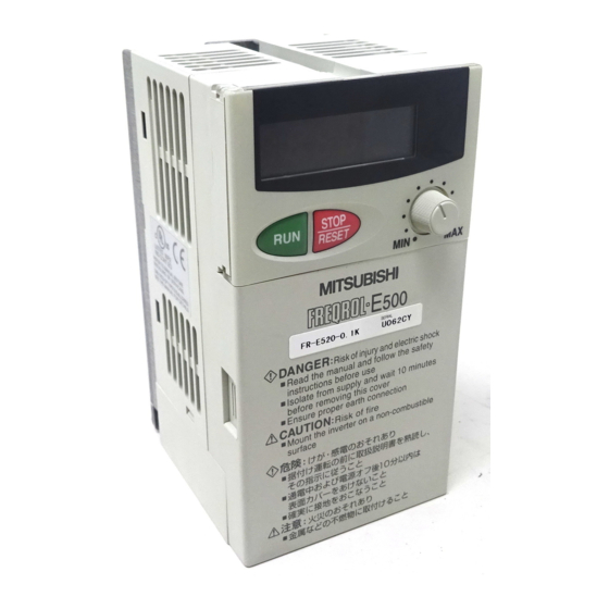
Mitsubishi FR-E 500 Instruction Manual
Fr-e 500 series transistorized inverter
Hide thumbs
Also See for FR-E 500:
- Instruction manual (207 pages) ,
- Manual (167 pages) ,
- Installation manual (28 pages)
Table of Contents
Advertisement
Quick Links
Advertisement
Table of Contents

Related Manuals for Mitsubishi FR-E 500


Summary of Contents for Mitsubishi FR-E 500
- Page 2 Thank you for choosing the Mitsubishi Transistorized inverter. This instruction manual gives handling information and precautions for use of this equipment. Incorrect handling might cause an unexpected fault. Before using the inverter, please read this manual carefully to use the equipment to its optimum.
-
Page 3: Safety Instructions
SAFETY INSTRUCTIONS 1. Electric Shock Prevention WARNING While power is on or when the inverter is running, do not open the front cover. You may get an electric shock. Do not run the inverter with the front cover removed. Otherwise, you may access the exposed high-voltage terminals or the charging part of the circuitry and get an electric shock. - Page 4 3. Injury Prevention CAUTION Apply only the voltage specified in the instruction manual to each terminal to prevent damage etc. Ensure that the cables are connected to the correct terminals. Otherwise, damage etc. may occur. Always make sure that polarity is correct to prevent damage etc. While power is on and for some time after power-off, do not touch the inverter or brake resistor as they are hot and you may get burnt.
- Page 5 ( 2 ) Wiring CAUTION Do not fit capacitive equipment such as a power factor correction capacitor, radio noise filter or surge suppressor to the output of the inverter. The connection orientation of the output cables U, V, W to the motor will affect the direction of rotation of the motor.
- Page 6 CAUTION When a 400V class motor is inverter-driven, it should be insulation-enhanced or surge voltages suppressed. Surge voltages attributale to the wiring constants may occur at the motor terminals, deteriorating the insulation of the motor. When parameter clear or all clear is performed, each parameter returns to the factory setting.
-
Page 7: Table Of Contents
CONTENTS 1 OUTLINE 1.1 Pre-Operation Information ..................1 1.1.1 Precautions for operation ..................1 1.2 Basic Configuration.....................3 1.2.1 Basic configuration ....................3 1.3 Structure ........................4 1.3.1 Appearance and structure ..................4 1.3.2 Removal and reinstallation of the front cover ............5 1.3.3 Removal and reinstallation of the wiring cover .............7 1.3.4 Removal and reinstallation of the accessory cover ..........8 1.3.5 Reinstallation and removal of the control panel............9 1.3.6 Removal of the control panel (FR-PA02-... - Page 8 3 OPERATION/CONTROL 3.1 Pre-Operation Information ..................48 3.1.1 Types of operation modes..................48 3.1.2 Power on ......................50 3.2 About the Control Panel....................51 3.2.1 Names and functions of the control panel (FR-PA02- )........51 3.2.2 Control panel mode is changed by pressing the key .........52 MODE 3.2.3 Monitoring......................52 3.2.4 Frequency setting ....................53...
- Page 9 4.2.8 Starting frequency (Pr. 13) .................80 4.2.9 Load pattern selection (Pr. 14) ................81 4.2.10 Jog operation (Pr. 15, Pr. 16) ................82 4.2.11 Stall prevention (Pr. 22, Pr. 23, Pr. 66).............83 4.2.12 Acceleration/deceleration pattern (Pr. 29) ............85 4.2.13 Regenerative brake duty (Pr. 30, Pr. 70)............86 4.2.14 Frequency jump (Pr.
- Page 10 4.2.43 Input terminal function selection (Pr. 180 to Pr. 183) ........148 4.2.44 Output terminal function selection (Pr. 190 to Pr. 192)........150 4.2.45 Cooling fan operation selection (Pr. 244) ............151 4.2.46 Slip compensation (Pr. 245 to Pr. 247) ............152 4.2.47 Ground fault detection at start (Pr. 249) (400V class does not have this function) ............153 4.2.48 Stop selection (Pr.
- Page 11 5.3.4 Insulation resistance test using megger ............179 5.3.5 Pressure test ....................179 5.3.6 Daily and Periodic Inspection ................180 5.3.7 Replacement of parts ..................183 5.3.8 Measurement of main circuit voltages, currents and powers......188 6 SPECIFICATIONS 6.1 Standard Specifications ..................191 6.1.1 Model specifications ..................191 6.1.2 Common specifications ..................194 6.1.3 Outline drawings....................196 APPENDIX...
- Page 12 Chapter 1 1.2 Basic Configuration............. 3 1.3 Structure ..............4 Chapter 2 <Abbreviations> ! PU Control panel and parameter Chapter 3 unit (FR-PU04) ! Inverter Mitsubishi transistorized inverter FR-E500 series ! Pr. Chapter 4 Parameter number Chapter 5 Chapter 6...
-
Page 13: Outline
Unpack the inverter and check the capacity plate on the front cover and the rating plate on the inverter side face to ensure that the product agrees with your order and the inverter is intact. 1) Inverter type Rating plate Capacity plate MITSUBISHI INVERTER Rating plate MODEL FR-E520-0.1K-NA Inverter type... - Page 14 OUTLINE ( 2 ) Preparation of instruments and parts required for operation Instruments and parts to be prepared depend on how the inverter is operated. Prepare equipment and parts as necessary. (Refer to page 48.) ( 3 ) Installation To operate the inverter with high performance for a long time, install the inverter in a proper place, in the correct direction, with proper clearances.
-
Page 15: Basic Configuration
1.2 Basic Configuration OUTLINE 1.2 Basic Configuration 1.2.1 Basic configuration The following devices are required to operate the inverter. Proper peripheral devices must be selected and correct connections made to ensure proper operation. Incorrect system configuration and connections can cause the inverter to operate improperly, its life to be reduced considerably, and in the worst case, the inverter to be damaged. -
Page 16: Structure
1.3 Structure OUTLINE 1.3 Structure 1.3.1 Appearance and structure (1) Front view (100V class, 200V class) (400V class) POWER lamp (yellow) Accessory cover ALARM lamp (red) Capacity plate Rating plate Front cover Wiring port cover for option (2) Without accessory cover and front cover (100V class, 200V class) (400V class) Inboard option... -
Page 17: Removal And Reinstallation Of The
OUTLINE 1.3.2 Removal and reinstallation of the front cover " " " " Removal (For the FR-E520-0.1K to 3.7K-NA, FR-E510W-0.1K to 0.75K-NA) The front cover is secured by catches in positions A and B as shown below. Push either A or B in the direction of arrows, and using the other end as a support, pull the front cover toward you to remove. - Page 18 OUTLINE (For the FR-E540-0.4K to 7.5K-NA) The front cover is fixed with catches in positions A, B and C. Push A and B in the directions of arrows at the same time and remove the cover using C as supporting points. "...
-
Page 19: Removal And Reinstallation Of The Wiring Cover
OUTLINE 1.3.3 Removal and reinstallation of the wiring cover " " " " Removal (For the FR-E520-0.1K to 7.5K-NA, FR-E510W-0.1K to 0.75K-NA) The wiring cover is fixed by catches in positions 1) and 2). Push either 1) or 2) in the direction of arrows and pull the wiring cover downward to remove. -
Page 20: Removal And Reinstallation Of The Accessory Cover
OUTLINE 1.3.4 Removal and reinstallation of the accessory cover " " " " Removal of the accessory cover Hold down the portion A indicated by the arrow and lift the right hand side using the portion B indicated by the arrow as a support, and pull out the accessory cover to the right. -
Page 21: Reinstallation And Removal Of The Control Panel
OUTLINE 1.3.5 Reinstallation and removal of the control panel To ensure safety, reinstall and removal the optional control panel (FR-PA02- ) after switching power off. The charging area and control printed board are exposed on the rear surface of the control panel. -
Page 22: Removal Of The Control Panel (Fr-Pa02- )
OUTLINE " " " " Using the connection cable for operation 1) Fit the rear cover option FR-E5P to the back surface of the optional control panel. 2) Securely plug one end of the connection cable into the PU connector of the inverter and the other end into the adaptor of the FR-E5P option to connect it to the control panel. -
Page 23: Exploded View
OUTLINE 1.3.7 Exploded view " " " " FR-E520-0.1K to 7.5K-NA " " " " FR-E510W-0.1K to 0.75K-NA Control panel (FR-PA02 Accessory cover Wiring cover Front cover " " " " FR-E540-0.4K to 7.5K-NA Control panel (FR-PA02- Accessory Front cover cover Wiring port cover for option... - Page 24 C H A P T E R 2 CHAPTER 2 INSTALLATION AND INSTALLATIONAND WIRINNG WIRING This chapter gives information on the basic "installation and wiring" for use of this product. Always read the instructions in this chapter before using the equipment.
-
Page 25: Installation And Wiring
2.1 Installation INSTALLATION AND WIRING 2 INSTALLATION AND WIRING 2.1 Installation 2.1.1 Instructions for installation For the FR-E520-0.1K to 0.75K-NA and FR-E510W-0.1K to 0.4K-NA, install the inverter with the accessory cover or control panel (FR-PA02- ) front cover open. <For the accessory cover> <For the control panel (FR-PA02 )>... - Page 26 INSTALLATION AND WIRING 7) Note the cooling method when the inverter is installed in an enclosure. When two or more inverters are installed or a ventilation fan is mounted in an enclosure, the inverters and ventilation fan must be installed in proper positions with extreme care taken to keep the ambient temperatures of the inverters with the permissible values.
-
Page 27: Wiring
2.2 Wiring INSTALLATION AND WIRING 2.2 Wiring 2.2.1 Terminal connection diagram " " " " 3-phase 200V power input " " " " 3-phase 400V power input Motor 3-phase AC power supply Ground 24VDC power output and external transistor common Jumper Note 5 Remove this jumper when... - Page 28 INSTALLATION AND WIRING " " " " Single-phase 100V power input Motor R (L Power supply S (L Ground Note: 1. To ensure safety, connect the power input to the inverter via a magnetic contactor and earth leakage circuit breaker or no-fuse breaker, and use the magnetic contactor to switch power on-off.
- Page 29 INSTALLATION AND WIRING ( 2 ) Description of the control circuit terminals Terminal Type Symbol Description Name When the STF Forward Turn on the STF signal to start forward and STR signals rotation start rotation and turn it off to stop. are turned on simultaneously, the stop...
- Page 30 INSTALLATION AND WIRING Terminal Type Symbol Description Name Contact output indicating that the output has been stopped by the inverter protective function activated. 230VAC 0.3A, 30VDC A, B, C Alarm output 0.3A. Alarm: discontinuity across B-C (continuity across A-C), normal: continuity Output across B-C (discontinuity across A-C).
-
Page 31: Wiring Of The Main Circuit
INSTALLATION AND WIRING 2.2.2 Wiring of the main circuit ( 1 ) Wiring instructions 1) It is recommended to use insulation-sleeved solderless terminals for power supply and motor wiring. 2) Power must not be applied to the output terminals (U, V, W) of the inverter. Otherwise the inverter will be damaged. - Page 32 INSTALLATION AND WIRING 6) Connect only the recommended optional brake resistor between the terminals P - PR (+ - PR). Keep terminals P-PR (+ - PR) of 0.1K or 0.2K open. These terminals must not be shorted. 0.1K and 0.2K do not accept the brake resistor. Keep terminals P-PR (+ - PR) open. Also, never short these terminals.
- Page 33 INSTALLATION AND WIRING ( 2 ) Terminal block layout of the power circuit FR-E520-0.1K-NA, 0.2K-NA, 0.4K-NA, FR-E520-1.5K-NA, 2.2K-NA, 3.7K-NA 0.75K-NA N/- P/+ P/+ PR Screw size (M4) Screw size (M4) Screw size (M3.5) Screw size (M4) Screw size (M3.5) FR-E520-5.5K-NA, 7.5K-NA Screw size (M5) Screw size (M5)
- Page 34 INSTALLATION AND WIRING ( 3 ) Cables, crimping terminals, etc. The following table lists the cables and crimping terminals used with the inputs (R (L S (L ), T (L )) and outputs (U, V, W) of the inverter and the torques for tightening the screws: 1) FR-E520-0.1K-NA to 7.5K-NA PVC insulated...
-
Page 35: Wiring Of The Control Circuit
INSTALLATION AND WIRING ( 4 ) Connection of the power supply and motor " " " " Three-phase power input Three-phase power supply 200V Three-phase power supply 400V Motor Ground Ground terminal No-fuse breaker Ground The power supply cables must be connected Connect the motor to U, V, W. - Page 36 INSTALLATION AND WIRING ( 2 ) Terminal block layout In the control circuit of the inverter, the terminals are arranged as shown below: Terminal screw size: M2.5 (200V class, 100V class) Terminal layout of control circuit (400V class) *AM for the 400V class inverter. ( 3 ) Wiring method 1) For wiring the control circuit, use cables after stripping their sheaths.
- Page 37 INSTALLATION AND WIRING 1) Use tweezers etc. to remove the connector in the sink logic position and fit it in the source logic position. Do this position changing before switching power on. Note: 1. Make sure that the front cover has been installed securely. 2.
- Page 38 INSTALLATION AND WIRING • When using an external power supply for transistor output, use terminal PC as a common to prevent misoperation caused by undesirable current. (Do not connect terminal SD of the inverter with terminal 0V of the external power supply.
- Page 39 INSTALLATION AND WIRING • When using an external power supply for transistor output, use terminal SD as a common to prevent misoperation caused by undesirable current. Inverter AY-80 24VDC (SD) (5) How to use the STOP signal The following connection example shows how to self-hold the start signals (forward rotation, reverse rotation).
-
Page 40: Connection To The Pu Connector
! Cable : Cable conforming to EIA568 (e.g. 10BASE-T cable) Example: SGLPEV 0.5mm×4P (Twisted pair cable, 4 pairs), MITSUBISHI CABLE INDUSTRIES, LTD. <When using the control panel> Note: The rear cover and junction adaptor are required since the circuit board is exposed in the back of the control panel. - Page 41 2. Cable : Cable conforming to EIA568 (such as 10BASE-T cable) Example: SGLPEV 0.5mm × 4P (Twisted pair cable, 4 pairs), Mitsubishi Cable Industries, Ltd. 3.*Commercially available converter examples Model: FA-T-RS40 Converter Nagoya Sales Office, Mitsubishi Electric Engineering Co., Ltd.
- Page 42 INSTALLATION AND WIRING <Wiring methods> 1) Wiring of one RS-485 computer and one inverter Computer Side Terminals Cable connection and signal direction Inverter PU connector Signal name Description 10 BASE-T Cable Receive data Receive data Send data Send data Request to send Request to send (Note 1) Clear to send...
-
Page 43: Connection Of Stand-Alone Option Units
INSTALLATION AND WIRING 2.2.5 Connection of stand-alone option units The inverter accepts a variety of stand-alone option units as required. Incorrect connection will cause inverter damage or an accident. Connect and operate the option unit carefully in accordance with the corresponding option unit manual. ( 1 ) Connection of the dedicated external brake resistor (option) (Cannot be connected to 0.1K and 0.2K) Connect a brake resistor across terminals P (+) and PR. - Page 44 INSTALLATION AND WIRING ( 2 ) Connection of the BU brake unit (option) Connect the BU brake unit correctly Inverter Motor R (L as shown on the right. Incorrect S (L connection will damage the inverter. T (L Remove jumpers. P (+) N (-) Discharge resistor T (Note 3)
- Page 45 INSTALLATION AND WIRING ( 3 ) Connection of the FR-HC high power factor converter (option unit) When connecting the high power factor converter (FR-HC) to suppress power harmonics, wire as shown below. Wrong connection will damage the high power factor converter and inverter.
-
Page 46: Design Information
INSTALLATION AND WIRING 2.2.6 Design information 1) Provide electrical and mechanical interlocks for MC1 and MC2 which are used for commercial power supply-inverter switch-over. When there is a commercial power supply-inverter switch-over circuit as shown below, the inverter will be damaged by leakage current from the power supply due to arcs generated at the time of switch-over or chattering caused by a sequence error. -
Page 47: Other Wiring
2.3 Other Wiring INSTALLATION AND WIRING 2.3 Other Wiring 2.3.1 Power supply harmonics Power supply harmonics may be generated from the converter section of the inverter, affecting the power supply equipment, power capacitor, etc. Power supply harmonics are different in generation source, frequency band and transmission path from radio frequency (RF) noise and leakage currents. -
Page 48: Inverter-Generated Noise And Reduction Techniques
INSTALLATION AND WIRING 2.3.2 Inverter-generated noise and reduction techniques Some noises enter the inverter causing it to incorrectly operate, and others are radiated by the inverter causing misoperation of peripheral devices. Though the inverter is designed to be insusceptible to noise, it handles low-level signals, so it requires the following basic measures to be taken. - Page 49 INSTALLATION AND WIRING 3) Measures against noises which are radiated by the inverter causing misoperation of peripheral devices. Inverter-generated noises are largely classified into those radiated by the cables connected to the inverter and inverter main circuit (I/O), those electromagnetically and electrostatically inducted to the signal cables of the peripheral devices close to the main circuit power supply, and those transmitted through the power supply cables.
- Page 50 INSTALLATION AND WIRING Noise Path Measures When devices which handle low-level signals and are susceptible to misoperation due to noise (such as instruments, receivers and sensors) are installed near the inverter and their signal cables are contained in the same panel as the inverter or are run near the inverter, the devices may be misoperated by air-propagated noise and the following measures must be taken: (1) Install easily affected devices as far away as possible from the...
- Page 51 INSTALLATION AND WIRING " " " " Data line filter Noise entry can be prevented by providing a data line filter for the detector or other cable. " " " " Data examples By using shielded cables as signal cables, By decreasing the carrier frequency, the induction noise can be reduced greatly (1/10 to noise terminal voltage* can be reduced.
-
Page 52: Leakage Currents And Countermeasures
! By using earth leakage circuit breakers designed for harmonic and surge suppression (e.g. Mitsubishi's Progressive Super Series) in the inverter's own line and other line, operation can be performed with the carrier frequency kept high (with low noise). -
Page 53: Inverter-Driven 400V Class Motor
INSTALLATION AND WIRING " " " " Countermeasures ! Use the electronic overcurrent protection of the inverter. ! Decrease the carrier frequency. Note that motor noise increases. Selection of Soft-PWM will make it unoffending. To ensure that the motor is protected not to be influenced by line-to-line leakage currents, we recommend the protection method which uses a temperature sensor to directly detect motor temperature. -
Page 54: Peripheral Devices
INSTALLATION AND WIRING 2.3.5 Peripheral devices ( 1 ) Selection of peripheral devices Check the capacity of the motor to be used with the inverter you purchased. Appropriate peripheral devices must be selected according to the capacity. Refer to the following list and prepare appropriate peripheral devices: No-Fuse Breaker (NFB) or Earth Power Magnetic Contactor... - Page 55 INSTALLATION AND WIRING " " " " Installation and selection of no-fuse breaker Install a no-fuse breaker (NFB) in the power supply side for protection of the inverter's primary wiring. Refer to the previous table and choose the NFB according to the inverter's power supply side power factor (which changes with the power supply voltage, output frequency and load).
- Page 56 INSTALLATION AND WIRING ( 2 ) Selecting the rated sensitivity current for the earth leakage circuit breaker When using the earth leakage circuit breaker with the inverter circuit, select its rated sensitivity current as follows, independently of the PWM carrier frequency: Example of leakage current per 1km in Leakage current example of 3-phase induction motor during commercial...
- Page 57 INSTALLATION AND WIRING <Example> × 5m × 70m 5.5mm 5.5mm (16.40 feet) (229.66 feet) NV Noise filter 3φ Inverter 200V 2.2kW (3HP) Ig1 Ign Note: 1. The earth leakage circuit breaker should be installed to the primary (power supply) side of the inverter. 2.
-
Page 58: Instructions For Compliance With U.s And Canadian Electrical Codes
INSTALLATION AND WIRING 2.3.6 Instructions for compliance with U.S and Canadian Electrical Codes (Standard to comply with: UL 508C) ( 1 ) Installation The above types of inverter have been approved as products for use in enclosure and approval tests were conducted under the following conditions. For enclosure design, refer to these conditions so that the ambient temperature of the inverter is 50°C (122°F) or less. -
Page 59: Instructions For Compliance With The European Standards
6Hz or higher 150 180200 when you set the electronic overcurrent Inverter output current (%) protection dedicated to the Mitsubishi (% to rated inverter output current) constant-torque motor. 2.3.7 Instructions for compliance with the European standards (The products conforming to the Low Voltage Directive carry the CE mark.) - Page 60 INSTALLATION AND WIRING ( 2 ) Low Voltage Directive 1) Our view of transistorized inverters for the Low Voltage Directive Transistorized inverters are covered by the Low Voltage Directive (Standard to comply with: DIN VDE0160 (200V class), EN50178 (400V class, 100V class)). 2) Compliance We have self-confirmed our inverters as products compliant to the Low Voltage Directive and place the CE mark on the inverters.
-
Page 61: Operation/Control
C H A P T E R 3 CHAPTER 3 O P E R A T I O N OPERATION/CONTROL This chapter provides the basic "operation/control" for use of this product. Always read this chapter before using the equipment. 3.1 Pre-Operation Information ........48 Chapter 1 3.2 About the Control Panel.......... -
Page 62: Pre-Operation Information
3.1 Pre-Operation Information 3 OPERATION/CONTROL 3.1 Pre-Operation Information 3.1.1 Types of operation modes The inverter can be operated in any of "PU operation mode", "external operation mode", "combined operation mode" and "communication operation mode". Prepare required instruments and parts according to the operation mode. For the way of changing the operation mode, refer to page 54. - Page 63 ( 3 ) Combined operation mode 1 (Pr. 79 "operation mode selection" = 3) The start signal is an external signal. The frequency setting signal is set using the optional control panel or parameter unit. Preparation ! Start signal ....Switch, relay, etc. ! Operation unit...Control panel (FR-PA02 ) or parameter unit (FR-PU04)
-
Page 64: Power On
3.1.2 Power on Before switching power on, check the following. " " " " Installation check Make sure that the inverter is installed correctly in a proper location. (Refer to page 12.) " " " " Wiring check Make sure that the main and control circuits are wired correctly. Make sure that the options and peripheral devices are selected and connected correctly. -
Page 65: About The Control Panel
3.2 About the Control Panel 3.2 About the Control Panel With the optional control panel (FR-PA02 ), you can run the inverter, set the frequency, monitor the operation command display, set parameters, and display an error. 3.2.1 Names and functions of the control panel (FR-PA02 Cover opened Unit indication Display... -
Page 66: Monitoring
3.2.2 Control panel mode is changed by pressing the MODE "Monitoring mode "Frequency setting "Parameter setting mode mode (Note) MODE MODE MODE MODE MODE MODE STOP STOP STOP RESET RESET RESET "Help mode "Operating mode MODE MODE MODE MODE STOP STOP RESET RESET... -
Page 67: Frequency Setting
3.2.4 Frequency setting In the PU operation mode, set the frequency value used for operation performed under the operation command given by the key ( key). This mode is displayed only in PU operation. To frequency monitoring "Frequency setting mode "Set frequency changing "Set frequency MODE... - Page 68 ( 1 ) Example: To change the Pr. 79 "operation mode selection" setting from "2" (external operation mode) to "1" (PU operation mode) (For details of Pr. 79, refer to page 110.) Press the key, to choose the MODE parameter setting mode. "Parameter setting mode Most significant Least significant...
-
Page 69: Operation Mode
3.2.6 Operation mode The operation mode change method which is shown below is only allowed when Pr. 79 "operation mode selection" is "0". "PU operation "External operation "PU jog operation MODE STOP RESET MODE MODE MODE To 3.2.7 Help mode Note: If the operation mode cannot be changed, refer to page 177. - Page 70 (1) Alarm history Four past alarms can be displayed with the key. ("." is appended to the most recent alarm.) When no alarm exists, E._ _0 is displayed. "Most recent alarm When alarm occurs Frequency Current PU EXT Voltage Energization time PU EXT PU EXT (2) Alarm history clear...
- Page 71 (3) Parameter clear Initializes the parameter values to the factory settings. The calibration values are not initialized. (Parameter values are not cleared by setting "1" in Pr. 77 "parameter write disable selection") Flicker Cancel Note: 1. In the FR-E520-0.1K to 7.5K-NA and FR-E510W-0.1K to 0.75K-NA, Pr. 122 "communication check time interval"...
-
Page 72: Operation
3.3 Operation 3.3 Operation 3.3.1 Pre-operation checks Before starting operation, check the following: " Safety Perform test operation after making sure that safety is ensured if the machine should become out of control. " Machine Make sure that the machine is free of damage. "... -
Page 73: External Operation Mode (Operation Using The External Frequency Setting Potentiometer And External Start Signal)
3.3.2 External operation mode (Operation using the external frequency setting potentiometer and external start signal) ( 1 ) Operation at 60Hz Operation command: Externally connected start signal. Frequency setting: Externally connected frequency setting potentiometer Step Description Image Power on → Operation mode check With the factory setting, the external operation mode is selected and the [EXT] indication is lit when power is switched on. -
Page 74: Pu Operation Mode (Operation Using The Control Panel)
3.3.3 PU operation mode (Operation using the control panel) ( 1 ) Using the control panel (FR-PA02 ) for operation at 60Hz with digital frequency setting Operation command: key or key of the control panel (FR-PA02 Frequency setting: Related parameters: Pr. 79 "operation mode selection". By repeating step 2 below during motor run, speed can be varied. -
Page 75: Combined Operation Mode 1 (Operation Using Both External Start Signal And Control Panel)
3.3.4 Combined operation mode 1 (Operation using both external start signal and control panel) When the start signal is provided externally (switch etc.) and the running frequency is set from the control panel (Pr. 79 = 3). The external frequency setting signal and PU's forward rotation, reverse rotation and STOP keys are not accepted. -
Page 76: Combined Operation Mode 2
3.3.5 Combined operation mode 2 When the running frequency is set from a potentiometer connected across terminals 2- 5 (frequency setting potentiometer) and the start signal is provided by the key or key of the control panel (FR-PA02 Operation command: key (or key) of the control panel (FR-PA02 ) or... - Page 77 C H A P T E R 4 CHAPTER 4 P A R A M E T E R S PARAMETERS This chapter explains the "parameters" of this product. With the factory settings, the inverter is designed to perform simple variable-speed operation. Set necessary parameter values according to the load and operating specifications.
-
Page 78: Parameters
4.1 Parameter List PARAMETERS 4 PARAMETERS 4.1 Parameter List 4.1.1 Parameter list Param- Minimum Custo- Func- Setting Factory Refer eter Name Setting tion Range Setting Number Increments Setting 6%/4% Torque boost (Note 1) 0 to 30% 0.1% (Note 11) Maximum frequency 0 to 120Hz 0.01Hz (Note 3) 120Hz 0 to 120Hz 0.01Hz (Note 3) - Page 79 PARAMETERS Param- Minimum Custo- Func- Setting Factory Refer eter Name Setting tion Range Setting Number Increments Setting Acceleration/deceleration 0, 1, 2 pattern Regenerative function 0, 1 selection 0 to 400Hz, 0.01Hz Frequency jump 1A 9999 9999 (Note 3) 0 to 400Hz, 0.01Hz Frequency jump 1B 9999...
- Page 80 PARAMETERS Param- Minimum Custo- Func- Setting Factory Refer eter Name Setting tion Range Setting Number Increments Setting Remote setting function 0, 1, 2 selection Shortest acceleration/ 0, 1, 2, deceleration mode 11, 12 Reference I for intelligent 0 to 500A, 0.01A 9999 mode...
- Page 81 PARAMETERS Param- Minimum Custo- Func- Setting Factory Refer eter Name Setting tion Range Setting Number Increments Setting Station number 0 to 31 Communication speed 48, 96, 192 0, 1 (data length 8) Stop bit length 10, 11 (data length 7) Parity check 0, 1, 2 presence/absence...
- Page 82 PARAMETERS Param- Minimum Custo- Func- Setting Factory Refer eter Name Setting tion Range Setting Number Increments Setting User group 1 registration 0 to 999 0 to User group 1 deletion 999,9999 User group 2 registration 0 to 999 0 to User group 2 deletion 999,9999 RL terminal function...
- Page 83 PARAMETERS Param- Minimum Custo- Func- Setting Factory Refer eter Name Setting tion Range Setting Number Increments Setting FM terminal calibration (Note 9) AM terminal calibration (Note 10) Frequency setting voltage 0 to 0 to 0.01Hz 0V 0Hz bias...
-
Page 84: List Of Parameters Classified By Purpose Of Use
PARAMETERS 4.1.2 List of parameters classified by purpose of use Set the parameters according to the operating conditions. The following list indicates purpose of use and corresponding parameters. Parameter Numbers Purpose of Use Parameter numbers which must be set Operation mode selection Pr. - Page 85 PARAMETERS Parameter Numbers Purpose of Use Parameter numbers which must be set Frequency meter calibration Pr. 54, Pr. 55, Pr. 56, Pr. 158, Pr. 900, Pr. 901 Monitor display on control panel (FR- Pr. 54, Pr. 55, Pr. 56, Pr. 158, Pr. 900, Pr. 901 PA02- ) or parameter unit (FR-PU04) Display of speed, etc.
-
Page 86: Parameters Recommended To Be Set By The User
PARAMETERS 4.1.3 Parameters recommended to be set by the user We recommend the following parameters to be set by the user. Set them according to the operation specifications, load, etc. Parameter Name Application Number Maximum frequency Used to set the maximum and minimum output Minimum frequency frequencies. -
Page 87: Parameter Function Details
4.2 Parameter Function Details PARAMETERS 4.2 Parameter Function Details 4.2.1 Torque boost (Pr. 0, Pr. 46) Related parameters Pr. 0 "torque boost" Pr. 3 "base frequency" Pr. 19 "base frequency voltage" Pr. 46 "second torque boost" Pr. 71 "applied motor" Pr. -
Page 88: Output Frequency Range (Pr. 1, Pr. 2, Pr. 18)
PARAMETERS 4.2.2 Output frequency range (Pr. 1, Pr. 2, Pr. 18) Related parameters Pr. 1 "maximum frequency" Pr. 13 "starting frequency" Pr. 38 "frequency at 5V (10V) Pr. 2 "minimum frequency" input" Pr. 39 "frequency at 20mA input" Pr. 18 "high-speed maximum frequency" Pr. -
Page 89: Base Frequency, Base Frequency Voltage (Pr. 3, Pr. 19, Pr. 47)
! Pr. 47 "Second V/F (base frequency) " is valid when the RT signal is on. (Note 3) ! Use Pr. 19 to set the base voltage (e.g. rated motor voltage). Note: 1. Set 60Hz in Pr. 3 "base frequency" when using a Mitsubishi constant-torque motor. -
Page 90: Multi-Speed Operation (Pr. 4, Pr. 5, Pr. 6, Pr. 24 To Pr. 27, Pr. 232 To Pr. 239)
PARAMETERS 4.2.4 Multi-speed operation (Pr. 4, Pr. 5, Pr. 6, Pr. 24 to Pr. 27, Pr. 232 to Pr. 239) Related parameters Pr. 4 "multi-speed setting (high speed)" Pr. 1 "maximum frequency" Pr. 5 "multi-speed setting (middle speed)" Pr. 2 "minimum frequency" Pr. -
Page 91: Acceleration/Deceleration Time (Pr. 7, Pr. 8, Pr. 20, Pr. 21, Pr. 44, Pr. 45)
PARAMETERS Note: 1. The multi-speed settings override the main speeds (across terminals 2-5, 4-5). 2. The multi-speeds can also be set in the PU or external operation mode. 3. For 3-speed setting, if two or three speeds are simultaneously selected, priority is given to the frequency setting of the lower signal. - Page 92 PARAMETERS Pr.20 Running frequency Time Pr.7 Pr.8 Pr.44 Pr.45 Acceleration Deceleration <Setting> ! Use Pr. 21 to set the acceleration/deceleration time and minimum setting increments: Set value "0" (factory setting)..0 to 3600s (minimum setting increments: 0.1s) Set value "1"......0 to 360s (minimum setting increments: 0.01s) ! Use Pr.
-
Page 93: Electronic Overcurrent Protection (Pr. 9, Pr. 48)
! Setting "0" makes the electronic overcurrent protection (motor protective function) invalid. (The inverter's protective function is valid.) ! When using Mitsubishi constant-torque motor, first set "1" in Pr. 71 to choose the 100% continuous torque characteristic in the low-speed range. Then, set the rated motor current in Pr. -
Page 94: Dc Injection Brake (Pr. 10 To Pr. 12)
PARAMETERS 4.2.7 DC injection brake (Pr. 10 to Pr. 12) Pr. 10 "DC injection brake operation frequency" Pr. 11 "DC injection brake operation time" Pr. 12 "DC injection brake voltage" By setting the DC injection brake voltage (torque), operation time and operation starting frequency, the stopping accuracy of positioning operation, etc. -
Page 95: Starting Frequency (Pr. 13)
PARAMETERS 4.2.8 Starting frequency (Pr. 13) Related parameters Pr. 13 "starting frequency" Pr. 2 "minimum frequency" You can set the starting frequency between 0 and 60Hz. ! Set the starting frequency at which the start signal is switched on. Parameter Factory Setting Output frequency... -
Page 96: Load Pattern Selection (Pr. 14)
PARAMETERS 4.2.9 Load pattern selection (Pr. 14) Related parameter Pr. 14 "load pattern selection" Pr. 0 "torque boost" Pr. 46 "second torque boost" Pr. 80 "motor capacity" Pr. 180 to Pr. 183 (input terminal function selection) You can select the optimum output characteristic (V/F characteristic) for the application and load characteristics. -
Page 97: Jog Operation (Pr. 15, Pr. 16)
PARAMETERS 4.2.10 Jog operation (Pr. 15, Pr. 16) Related parameters Pr. 15 "jog frequency" Pr. 20 "acceleration/deceleration reference frequency" Pr. 16 "jog acceleration/deceleration time" Pr. 21 "acceleration/deceleration time increments" Jog operation can be started and stopped by selecting the jog mode from the control panel and pressing and releasing the key ( key). -
Page 98: Stall Prevention (Pr. 22, Pr. 23, Pr. 66)
PARAMETERS 4.2.11 Stall prevention (Pr. 22, Pr. 23, Pr. 66) Related parameters Pr. 22 "stall prevention operation level" Pr. 9 "electronic thermal O/L relay" Pr. 48 "second electronic Pr. 23 "stall prevention operation overcurrent protection" level compensation factor Pr. 73 "0-5V/0-10V selection" at double speed"... - Page 99 PARAMETERS <Setting> ! In Pr. 22, set the stall prevention operation level. Normally set it to 150% (factory setting). Set "0" in Pr. 22 to disable the stall prevention operation. ! To reduce the stall prevention operation level in the high-frequency range, set the reduction starting frequency in Pr.
-
Page 100: Acceleration/Deceleration Pattern (Pr. 29)
PARAMETERS 4.2.12 Acceleration/deceleration pattern (Pr. 29) Related parameters Pr. 29 "acceleration/deceleration pattern" Pr. 3 "base frequency" Pr. 7 "acceleration time" Pr. 8 "deceleration time" Pr. 20 "acceleration/deceleration reference frequency" Set the acceleration/deceleration pattern. Pr. 44 "second acceleration/deceleration time" Parameter Factory Setting Pr. -
Page 101: Regenerative Brake Duty (Pr. 30, Pr. 70)
PARAMETERS 4.2.13 Regenerative brake duty (Pr. 30, Pr. 70) Pr. 30 "regenerative function selection" Pr. 70 "special regenerative brake duty" ! When making frequent starts/stops, use the optional "brake resistor" to increase the regenerative brake duty. (more than 0.4K) Parameter Factory Setting Number... -
Page 102: Frequency Jump (Pr. 31 To Pr. 36)
PARAMETERS 4.2.14 Frequency jump (Pr. 31 to Pr. 36) Pr. 31 "frequency jump 1A" Pr. 32 "frequency jump 1B" Pr. 33 "frequency jump 2A" Pr. 34 "frequency jump 2B" Pr. 35 "frequency jump 3A" Pr. 36 "frequency jump 3B" ! When it is desired to avoid resonance attributable to the natural frequency of a mechanical system, these parameters allow resonant frequencies to be jumped. -
Page 103: Speed Display (Pr. 37)
PARAMETERS 4.2.15 Speed display (Pr. 37) Related parameter Pr. 37 "speed display" Pr. 52 "control panel/PU main display data selection" The unit of the output frequency display of the control panel (FR-PA02- ) and PU (FR-PU04) can be changed from the frequency to the motor speed or machine speed. Parameter Factory Setting... -
Page 104: Frequency At 5V (10V) Input (Pr. 38)
PARAMETERS 4.2.16 Frequency at 5V (10V) input (Pr. 38) Related parameters Pr. 38 "frequency at 5V (10V) input" Pr. 73 "0-5V/0-10V selection" Pr. 79 "operation mode selection" Pr. 902 "frequency setting voltage bias" Pr. 903 "frequency setting voltage gain" ! You can set the frequency Pr.38 provided when the Output frequency... -
Page 105: Up-To-Frequency Sensitivity (Pr. 41)
PARAMETERS 4.2.18 Up-to-frequency sensitivity (Pr. 41) Related parameters Pr. 41 "up-to-frequency sensitivity" Pr. 190 "RUN terminal function selection" Pr. 191 "FU terminal function selection" Pr. 192 "A, B, C terminal function selection" The ON range of the up-to-frequency signal (SU) output when the output frequency reaches the running frequency can be adjusted between 0 and ±100% of the running frequency. - Page 106 PARAMETERS ! You can also set the detection of the frequency used exclusively for reverse rotation. This function is effective for switching the timing of electromagnetic brake operation between forward rotation (rise) and reverse rotation (fall) during vertical lift operation etc. Parameter Factory Setting...
-
Page 107: Monitor Display (Pr. 52, Pr. 54, Pr. 158)
PARAMETERS 4.2.20 Monitor display (Pr. 52, Pr. 54, Pr. 158) Related parameters Pr. 52 "control panel/PU main display Pr. 37 "speed display" data selection" Pr. 55 "frequency monitoring reference" Pr. 54 "FM terminal function selection" Pr. 56 "current monitoring reference" Pr. - Page 108 PARAMETERS When 100 is set in Pr. 52, the monitored values during stop and during operation differ as indicated below: Pr. 52 During During stop During operation operation/during stop Output Output frequency Set frequency Output frequency frequency Output current Output current Output voltage Output voltage Alarm display...
-
Page 109: Monitoring Reference (Pr. 55, Pr. 56)
PARAMETERS 4.2.21 Monitoring reference (Pr. 55, Pr. 56) Related parameters Pr. 55 "frequency monitoring reference" Pr. 54 "FM terminal function selection" Pr. 56 "current monitoring reference" Pr. 158 "AM terminal function selection" Pr. 900 "FM terminal calibration" Set the frequency or current which is referenced Pr. -
Page 110: Automatic Restart After Instantaneous Power Failure (Pr. 57, Pr. 58)
PARAMETERS 4.2.22 Automatic restart after instantaneous power failure (Pr. 57, Pr. 58) Pr. 57 "restart coasting time" Pr. 58 "restart cushion time" ! You can restart the inverter without stopping the motor (with the motor coasting) when power is restored after an instantaneous power failure. Parameter Number Factory Setting Setting Range... - Page 111 PARAMETERS Note: 1. Automatic restart after instantaneous power failure uses a reduced-voltage starting system in which the output voltage is raised gradually with the preset frequency unchanged, independently of the coasting speed of the motor. As in the FR-A024/A044, a motor coasting speed detection system (speed search system) is not used but the output frequency before an instantaneous power failure is output.
-
Page 112: Remote Setting Function Selection (Pr. 59)
PARAMETERS 4.2.23 Remote setting function selection (Pr. 59) Related parameters Pr. 59 "remote setting function selection" Pr. 1 "maximum frequency" Pr. 7 "acceleration time" If the operator panel is located away from the Pr. 8 "deceleration time" control box, you can use contact signals to Pr. - Page 113 PARAMETERS Note: 1. The frequency can be varied by RH (acceleration) and RM (deceleration) between 0 and the maximum frequency (Pr. 1 or Pr. 18 setting). 2. When the acceleration or deceleration signal switches on, the set frequency varies according to the slope set in Pr. 44 or Pr. 45. The output frequency acceleration/deceleration times are as set in Pr.
-
Page 114: Shortest Acceleration/Deceleration Mode (Pr. 60 To Pr. 63)
PARAMETERS 4.2.24 Shortest acceleration/deceleration mode (Pr. 60 to Pr. 63) Pr. 60 "shortest acceleration/deceleration mode" Related parameters Pr. 7 "acceleration time" Pr. 61 "reference I for intelligent mode" Pr. 8 "deceleration time" Pr. 62 "ref. I for intelligent mode accel" Pr. - Page 115 PARAMETERS <Setting> • Set the parameters when it is desired to improve the performance in the shortest acceleration/deceleration mode. ( 1 ) Pr. 61 "reference I for intelligent mode" Setting Reference Current 9999 (factory setting) Referenced from rated inverter current 0 to 500A Referenced from setting (rated motor current) ( 2 ) Pr.
-
Page 116: Retry Function (Pr. 65, Pr. 67 To Pr. 69)
PARAMETERS 4.2.25 Retry function (Pr. 65, Pr. 67 to Pr. 69) Pr. 65 "retry selection" Pr. 67 "number of retries at alarm occurrence" Pr. 68 "retry waiting time" Pr. 69 "retry count display erasure" When any protective function (major fault) is activated and the inverter stops its output, the inverter itself resets automatically and performs retries. - Page 117 PARAMETERS Use Pr. 67 to set the number of retries at alarm occurrence. Pr. 67 Setting Number of Retries Alarm Signal Output Retry is not made. 1 to 10 1 to 10 times Not output. 101 to 110 1 to 10 times Output.
-
Page 118: Applied Motor (Pr. 71)
Pr. 96 "auto-tuning setting/status" Set the motor used. ! When using the Mitsubishi constant-torque motor, set "1" in Pr. 71 for either V/F control or general-purpose magnetic flux vector control. The electronic overcurrent protection is set to the thermal characteristic of the constant-torque motor. -
Page 119: Pwm Carrier Frequency (Pr. 72, Pr. 240)
PARAMETERS 4.2.27 PWM carrier frequency (Pr. 72, Pr. 240) Pr. 72 "PWM frequency selection" Pr. 240 "Soft-PWM setting" You can change the motor tone. ! By parameter setting, you can select Soft-PWM control which changes the motor tone. ! Soft-PWM control changes motor noise from a metallic tone into an unoffending complex tone. -
Page 120: Voltage Input (Pr. 73)
PARAMETERS 4.2.28 Voltage input (Pr. 73) Related parameters Pr. 73 "0-5V/0-10V selection" Pr. 22 "stall prevention operation level" Pr. 38 "frequency at 5V (10V) input" ! You can change the input (terminal 2) specifications in response to the frequency setting voltage signal. When entering 0 to 10VDC, always make this setting. Parameter Factory Setting... -
Page 121: Input Filter Time Constant (Pr. 74)
PARAMETERS 4.2.29 Input filter time constant (Pr. 74) Pr. 74 "filter time constant" You can set the input section's internal filter constant for an external voltage or current frequency setting signal. ! Effective for eliminating noise in the frequency setting circuit. ! Increase the filter time constant if steady operation cannot be performed due to noise. - Page 122 PARAMETERS <Setting> Pr. 75 PU Disconnection PU Stop Reset Selection Setting Detection Selection Reset input normally enabled. Pressing the If the PU is disconnected, Reset input enabled only when the STOP operation will be continued. RESET protective function is activated. decelerates the When the PU is Reset input normally enabled.
-
Page 123: Parameter Write Inhibit Selection (Pr. 77)
PARAMETERS Note: 1. By entering the reset signal (RES) during operation, the inverter shuts off output while it is reset, the data of the electronic overcurrent protection and regenerative brake duty are reset, and the motor coasts. 2. The PU disconnection detection function judges that the PU is disconnected when it is removed from the inverter for more than 1 second. -
Page 124: Reverse Rotation Prevention Selection (Pr. 78)
PARAMETERS Note: 1. The parameters half-tone screened in the parameter list can be set at any time. 2. If Pr. 77 = "2", the values of Pr. 23, Pr. 66, Pr. 71, Pr. 79, Pr. 80, Pr. 83, Pr. 84, Pr. 96, Pr. 180 to Pr. 183 and Pr. 190 to Pr. 192 cannot be written during operation. -
Page 125: Operation Mode Selection (Pr. 79)
PARAMETERS 4.2.33 Operation mode selection (Pr. 79) Related parameters Pr. 79 "operation mode selection" Pr. 4 to Pr. 6, Pr. 24 to Pr. 27, Pr. 232 to Pr. 239 Used to select the operation mode of the inverter. "multi-speed operation" The inverter can be run from the control panel or Pr. - Page 126 PARAMETERS Note: Either "3" or "4" may be set to select the PU/external combined operation. These settings differ in starting method. ( 1 ) Switch-over mode During operation, you can change the current operation mode to another operation mode. Operation Mode Switching Control/Operating Status Switching External operation to PU...
- Page 127 PARAMETERS 2) Function MRS Signal Function/Operation Output stopped during external operation. Operation mode can be switched to PU operation mode. Parameter values can be rewritten in PU operation mode. PU operation allowed. Forcibly switched to external operation mode. External operation allowed. Switching to PU operation mode inhibited.
-
Page 128: General-Purpose Magnetic Flux Vector Control Selection (Pr. 80)
PARAMETERS ( 3 ) Operation mode switching by external signal 1) Preparation Set "8" (switching to other than external operation mode) in Pr. 79. Use any of Pr. 180 to Pr. 183 (input terminal function selection) to set the terminal used for X16 signal input. - Page 129 (Note) vector control Note: The setting range changes with the inverter: 0.2kW to 7.5kW, 9999 for the 400V class. ! When using Mitsubishi's constant-torque motor (SF-JRCA), set "1" in Pr. 71. (When using the SF-JRC, perform the offline auto tuning.)
-
Page 130: Offline Auto Tuning Function (Pr. 82 To Pr. 84, Pr. 90, Pr. 96)
" The Mitsubishi standard motor (SF-JR0.4kW or more) or Mitsubishi constant-torque motor (By SF-JRCA 200V class and 4-pole motor of 0.4kW to 7.5kW) allows general-purpose magnetic flux vector control operation to be performed without using the offline auto tuning function. - Page 131 ! Standard motor ..............Pr. 71 = "3" or "103" ! Constant-torque motor............Pr. 71 = "13" or "113" ! Mitsubishi standard motor SF-JR 4 poles (1.5kW (2HP) or less)........Pr. 71 = "23" or "123" Note: Pr. 83 and Pr. 84 are only displayed when the general-purpose magnetic flux vector control is selected.
- Page 132 Setting Description Number 0 to 500A Set the rated motor current (A). 0, 100 Thermal characteristics suitable for standard motor Thermal characteristics suitable for Mitsubishi's constant- 1, 101 torque motor 3, 103 Standard motor 13, 113 Constant-torque motor Select "offline auto tuning setting"...
- Page 133 PARAMETERS ( 3 ) Monitoring the offline tuning status When the parameter unit (FR-PU04) is used, the Pr. 96 value is displayed during tuning on the main monitor as shown below. When the control panel is used, the same value as on the PU is only displayed: ! Control panel display (FR-PA02 (For inverter trip) 2.
- Page 134 PARAMETERS 4) Error display definitions Error Display Error Cause Remedy Inverter trip Make setting again. Increase Current limit (stall prevention) function was acceleration/deceleration time. activated. Set "1" in Pr. 156. Converter output voltage reached 75% of Check for fluctuation of power rated value.
- Page 135 PARAMETERS <Setting the motor constant as desired> " To set the motor constant without using the offline auto tuning data <Operating procedure> 1. Set any of the following values in Pr. 71: Star Connection Motor Delta Connection Motor Standard motor 5 or 105 6 or 106 Setting...
-
Page 136: Computer Link Operation (Pr. 117 To Pr. 124, Pr. 342)
PARAMETERS 4.2.36 Computer link operation (Pr. 117 to Pr. 124, Pr. 342) Pr. 117 "station number" Pr. 118 "communication speed" Pr. 119 "stop bit length" Pr. 120 "parity check presence/absence" Pr. 121 "number of communication retries" Pr. 122 "communication check time interval" Pr. - Page 137 PARAMETERS <Setting> To make communication between the personal computer and inverter, the communication specifications must be set to the inverter initially. If initial setting is not made or there is a setting fault, data transfer cannot be made. Note: After making the initial setting of the parameters, always reset the inverter. After you have changed the communication-related parameters, communication cannot be made unit the inverter is reset.
- Page 138 PARAMETERS <Computer programming> ( 1 ) Communication protocol Data communication between the computer and inverter is performed using the following procedure: Data read Computer ↓ (Data flow) Inverter Time Inverter ↓ (Data flow) Data write Computer *1. If a data error is detected and a retry must be made, execute retry operation with the user program.
- Page 139 PARAMETERS ( 3 ) Data format Data used is hexadecimal. Data is automatically transferred in ASCII between the computer and inverter. 1) Data format types (1) Communication request data from computer to inverter [Data write] Inverter Instruction Format A station Data check code...
- Page 140 PARAMETERS 3) Reply data from inverter to computer during data read [No data error detected] [Data error detected] Inverter Read Format E station check data number Format F 10 11 Inverter Inverter Read Error Format E' station station code data check number number...
- Page 141 PARAMETERS 5) Waiting time Specify the waiting time between the receipt of data at the inverter from the computer and the transmission of reply data. Set the waiting time in accordance with the response time of the computer between 0 and 150ms in 10ms increments (e.g.
-
Page 142: Communication Specification
PARAMETERS [Data sending time calculation expression] Communication Number of data specification Data sending × × characters Communication speed (Total number of bits) time (s) (Refer to page 124) (bps) (See below) " Communication specification Name Number of Bits 1 bit Stop bit length 2 bits 7 bits... - Page 143 PARAMETERS 8) Error code If any error is found in the data received by the inverter, its definition is sent back to the computer together with the NAK code. (Refer to page 132.) Note: 1. When the data from the computer has an error, the inverter will not accept that data.
-
Page 144: Setting Items And Set Data
PARAMETERS <Setting items and set data> After completion of parameter settings, set the instruction codes and data then start communication from the computer to allow various types of operation control and monitoring. Number of Data Instruction Digits Item Description (Data Code code FF=1) - Page 145 PARAMETERS Number of Data Instruction Digits Item Description (Data Code code FF=1) b0: Inverter running (RUN) b1: Forward rotation 0 0 0 0 0 0 b2: Reverse rotation (For example 1) Inverter status b3: Up to frequency (SU) 2 digits [Example 1] H02 ...
- Page 146 PARAMETERS Number of Data Instruction Digits Item Description (Data Code code FF=1) H00 to H6C and H80 to HEC parameter values are changed. Read H00: Pr. 0 to Pr. 96 values are accessible. H01: Pr. 117 to Pr. 158 and Pr. 900 to Pr. 905 Link values are accessible.
- Page 147 PARAMETERS <Error Code List> The corresponding error code in the following list is displayed if an error is detected in any communication request data from the computer: Error Item Definition Inverter Operation Code number errors consecutively Computer NAK detected in communication request data error from the computer is greater than allowed number of retries.
- Page 148 PARAMETERS ( 5 ) Communication specifications for RS-485 communication Operation Mode Operation Communication Item Location Operation from PU External Operation Connector Run command (start) Enable Disable Enable Running frequency setting Enable (Combined operation mode) Computer user Monitoring Enable Enable program via Parameter write Enable (*2) Disable (*2)
-
Page 149: Pid Control (Pr. 128 To Pr. 134)
PARAMETERS 4.2.37 PID control (Pr. 128 to Pr. 134) Related parameters Pr. 128 "PID action selection" Pr. 73 "0-5V/0-10V selection" Pr. 79 "operation mode selection" Pr. 129 "PID proportional band" Pr. 180 to Pr. 183 (input terminal function selection) Pr. 130 "PID integral time" Pr. - Page 150 PARAMETERS ( 2 ) PID action overview 1) PI action A combination of proportional control action (P) and integral control action (I) for providing a manipulated variable in response to deviation and changes with time. [Operation example for stepped changes of process value] Note: PI action is the sum of P and I Deviation Set point...
- Page 151 PARAMETERS 4) Reverse action Increases the manipulated variable (output frequency) if deviation X (set point - process value) is positive, and decreases the manipulated variable if deviation is negative. Set point Deviation [Heating] Cold → fi up X>0 Set point Hot →...
- Page 152 PARAMETERS ( 3 ) Wiring example ! Pr. 190 = 14 ! Pr. 191 = 15 ! Pr. 192 = 16 Inverter Pump Motor R (L Power supply S (L T (L Forward rotation Reverse rotation For 2-wire For 3-wire type type (Note 2)
- Page 153 PARAMETERS ( 4 ) I/O signals Signal Terminal Used Function Description Set point input Enter the set point for PID control. Enter the 4 to 20mADC process value signal Process value input from the detector. Output to indicate that the process value Upper limit output signal exceeded the upper limit value.
- Page 154 PARAMETERS ( 5 ) Parameter setting Parameter Setting Name Description Number No PID action action For heating, pressure control, etc. PID reverse action selection For cooling, etc. PID forward action If the proportional band is narrow (parameter setting is small), the manipulated variable varies greatly with a slight change of the process value.
- Page 155 PARAMETERS ( 7 ) Calibration example (A detector of 4mA at 0°C (32°F) and 20mA at 50°C (122°F) is used to adjust the room temperature to 25°C (77°F) under PID control. The set point is given to across inverter terminals 2-5 (0-5V).) START Determine the set point.
- Page 156 PARAMETERS <Set point input calibration> 1. Apply the input voltage of 0% set point setting (e.g. 0V) to across terminals 2-5. 2. Make calibration using Pr. 902. At this time, enter the frequency which should be output by the inverter at the deviation of 0% (e.g. 0Hz). 3.
-
Page 157: Output Current Detection Function (Pr. 150, Pr.151)
PARAMETERS 4.2.38 Output current detection function (Pr. 150, Pr.151) Related parameters Pr. 150 "output current detection level" Pr. 190 to Pr. 192 (output terminal function Pr. 151 "output current detection period" selection) ! If the output current remains higher than the Pr. 150 setting during inverter operation for longer than the time set in Pr. -
Page 158: Zero Current Detection (Pr. 152, Pr.153)
PARAMETERS 4.2.39 Zero current detection (Pr. 152, Pr.153) Related parameters Pr. 152 "zero current detection level" Pr. 190 to Pr. 192 (output terminal function selection) Pr. 153 "zero current detection period" When the inverter's output current falls to "0", torque will not be generated. This may cause a gravity drop when the inverter is used in vertical lift application. -
Page 159: Stall Prevention Function And Current Limit Function (Pr. 156)
PARAMETERS CAUTION The zero current detection level setting should not be too high, and the zero current detection time setting should not be too long. Otherwise, the detection signal may not be output when torque is not generated at a low output current. - Page 160 PARAMETERS <Setting> Refer to the following tables and set the parameter as required. Stall Prevention Stall Prevention Operation Operation Signal Signal Selection Output Selection Output ( ( ( ( : Activated (: Activated Fast-Response Fast-Response " " " " " : Not activated Operation Operation : Not activated...
-
Page 161: User Group Selection (Pr. 160, Pr. 173 To Pr. 176)
PARAMETERS 4.2.41 User group selection (Pr. 160, Pr. 173 to Pr. 176) Pr. 160 "user group read selection" Pr. 173 "user group 1 registration" Pr. 174 "user group 1 deletion" Pr. 175 "user group 2 registration" Pr. 176 "user group 2 deletion" Among all parameters, a total of 32 parameters can be registered to two different user groups. - Page 162 PARAMETERS ( 3 ) Set the required value in Pr. 160 to make the user group or groups valid or invalid. Pr. 160 Setting Description Previous parameters read User group 1's parameters read User group 2's parameters read User group 1 and 2 parameters read Note: 1.
-
Page 163: Actual Operation Hour Meter Clear (Pr. 171)
PARAMETERS 4.2.42 Actual operation hour meter clear (Pr. 171) Pr. 171 "actual operation hour meter Related parameter clear" Pr. 52 "Control panel/PU main display data selection" You can clear the monitor (actual operation hour) value which is selected when Pr. 52 is "23". - Page 164 PARAMETERS <Setting> Refer to the following list and set the parameters. Signal Related Setting Function Name Parameters Pr. 4 to Pr. 6 Pr. 59 = 0 Low-speed operation command Pr. 24 to Pr. 27 Pr. 232 to Pr. 239 Pr. 59 = 1, 2 * Remote setting (setting clear) Pr.
-
Page 165: Output Terminal Function Selection (Pr. 190 To Pr. 192)
PARAMETERS 4.2.44 Output terminal function selection (Pr. 190 to Pr. 192) Pr. 190 "RUN terminal function selection" Pr. 191 "FU terminal function selection" Pr. 192 "A, B, C terminal function selection" You can change the functions of the open collector and contact output terminals. Parameter Terminal Factory... -
Page 166: Cooling Fan Operation Selection (Pr. 244)
PARAMETERS Pr. 232 to Pr. 239 ' ' Refer to Pr. 4. Pr. 240 ' ' Refer to Pr. 72. 4.2.45 Cooling fan operation selection (Pr. 244) Pr. 244 "cooling fan operation selection" You can control the operation of the cooling fan built in the inverter (whether there is a cooling fan or not depends on the models. -
Page 167: Slip Compensation (Pr. 245 To Pr. 247)
PARAMETERS 4.2.46 Slip compensation (Pr. 245 to Pr. 247) Pr. 245 "rated motor slip" Pr. 246 "slip compensation response time" Pr. 247 "constant-output region slip compensation selection" The inverter output current may be used to assume motor slip to keep the motor speed constant. -
Page 168: Ground Fault Detection At Start (Pr. 249)
PARAMETERS 4.2.47 Ground fault detection at start (Pr. 249) (400V class does not have this function) Pr. 249 "ground fault detection at start" You can select whether ground fault detection at start is made or not. Ground fault detection is made only immediately after the start signal is input to the inverter. If a ground fault occurs during operation, the protective function is not activated. -
Page 169: Stop Selection (Pr. 250)
PARAMETERS 4.2.48 Stop selection (Pr. 250) Related parameters Pr. 250 "stop selection" Pr. 7 "acceleration time" Pr. 8 "deceleration time" Pr. 44 "second acceleration/ deceleration time" Pr. 45 "second deceleration time" Used to select the stopping method (deceleration to a stop or coasting) when the start signal (STF/STR) switches off. -
Page 170: Output Phase Failure Protection Selection (Pr. 251)
PARAMETERS When the Pr. 250 value is 8888, the functions of terminals STF and STR change as shown below: STF = start signal, STR = rotation direction signal Inverter Operating Status Stop Forward rotation Reverse rotation When the Pr. 250 value is any of 1000 to 1100 s, the functions of terminals STF and STR are the same as when the Pr. -
Page 171: Meter (Frequency Meter) Calibration (Pr. 900) (200V Class, 100V Class)
PARAMETERS 4.2.50 Meter (frequency meter) calibration (Pr. 900) (200V class, 100V class) Related parameters Pr. 900 "FM terminal calibration" Pr. 54 "FM terminal function selection" Pr. 55 "frequency monitoring reference" Pr. 56 "current monitoring reference" " By using the control panel or parameter unit, you can calibrate a meter connected to terminal FM to full scale deflection. - Page 172 PARAMETERS <Operation procedure> ! When using the control panel (FR-PA02- 1) Select the PU operation mode. 2) Set the running frequency. 3) Press the key. 4) Read Pr. 900 "FM terminal calibration". 5) Press the key to run the inverter. (Motor need not be connected.) 6) Hold down the key to adjust the meter pointer to a required position.
-
Page 173: Meter (Frequency Meter) Calibration (Pr. 901) (400V Class)
PARAMETERS 4.2.51 Meter (frequency meter) calibration (Pr. 901) (400V class) Related parameters Pr. 901 "AM terminal calibration" Pr. 55 "frequency monitoring reference" Pr. 56 "current monitoring reference" Pr. 158 "AM terminal function selection" " By using the control panel or parameter unit, you can calibrate a meter connected to terminal AM to full scale deflection. - Page 174 PARAMETERS <Operation procedure> ! When using the control panel (FR-PA02- 1) Select the PU operation mode. 2) Set the running frequency. 3) Press the key. 4) Read Pr. 901 "AM terminal calibration". 5) Press the key to run the inverter. (Motor need not be connected.) 6) Hold down the key to adjust the meter pointer to a required position.
-
Page 175: Biases And Gains Of The Frequency Setting Voltage (Current)
PARAMETERS 4.2.52 Biases and gains of the frequency setting voltage (current) (Pr. 902 to Pr. 905) Related parameters Pr. 902 "frequency setting voltage bias" Pr. 38 "frequency at 5V (10V) input" Pr. 903 "frequency setting voltage gain" Pr. 39 "frequency at 20mA input"... -
Page 176: Adjustment Procedure
PARAMETERS Pr. 903 "frequency setting voltage gain" (Pr.902, Pr. 904, Pr. 905 can also be adjusted similarly.) <Adjustment procedure> When using an external frequency setting signal to set the frequency. (1)Power-on (monitoring mode) MODE STOP RESET (2)Choose the PU operation mode. 1) Using the key, make sure that the PU operation mode has been selected. - Page 177 PARAMETERS 2) Set "1" (PU operation mode) in Pr. 79 "operation mode selection". Example:To change the external operation mode (Pr. 79=2) to the PU operation mode (Pr. 79=1) Using the key, MODE choose the "parameter setting mode" as in 1). "Parameter setting mode Most significant Least significant...
- Page 178 PARAMETERS (3)Read Pr. 903 and show the current setting of the gain frequency. (Pr. 902, Pr. 904 and Pr. 905 can also be adjusted similarly.) "Parameter setting mode Using the key, choose the "parameter setting mode" as in (2)-1). MODE MODE STOP RESET...
- Page 179 PARAMETERS 1) When not adjusting the gain voltage → go to (5) 2) When adjusting any point by applying a voltage → go to (6) 3) When adjusting any point without applying a voltage → go to (7) (5)How to adjust the gain frequency only without the voltage being adjusted "Press the "Analog voltage A/D value (%) key once to display...
- Page 180 PARAMETERS (8)Press the key to shift to the next parameter. (9)Re-set Pr. 79 "operation mode selection" according to the operation mode to be used. Note: 1. If the Pr. 903 or Pr. 905 (gain adjustment) value is changed, the Pr. 20 value does not change.
- Page 181 C H A P T E R 5 CHAPTER 5 PROTECTIVE PROTECTIVE FUNCTIONS FUNCTIONS This chapter explains the "protective functions" of this product. Always read the instructions before using the equipment. 5.1 Errors (Alarms) ............166 5.2 Troubleshooting ............175 Chapter 1 5.3 Precautions for Maintenance and Inspection ..
-
Page 182: Protective Functions
5.1 Errors (Alarms) PROTECTIVE FUNCTIONS 5 PROTECTIVE FUNCTIONS 5.1 Errors (Alarms) If any fault has occurred in the inverter, the corresponding protective function is activated to bring the inverter to an alarm stop and automatically give the corresponding error (alarm) indication on the optional control panel or the panel display. - Page 183 PROTECTIVE FUNCTIONS Operation Panel Indication E. OC3 FR-PU04 OC During Dec Overcurrent shut-off during deceleration Name When the inverter output current reaches or exceeds approximately 200% of the rated current during deceleration Description (other than acceleration or constant speed), the protective circuit is activated to stop the inverter output.
- Page 184 PROTECTIVE FUNCTIONS Operation Panel Indication E. OV3 FR-PU04 OV During Dec Regenerative overvoltage shut-off during deceleration or stop Name If regenerative energy causes the inverter's internal main circuit DC voltage to reach or exceed the specified value, the Description protective circuit is activated to stop the inverter output. It may also be activated by a surge voltage generated in the power supply system.
- Page 185 PROTECTIVE FUNCTIONS Operation Panel Indication E. FIN FR-PU04 H/Sink O/Temp Fin overheat Name If the cooling fin overheats, the overheat sensor is actuated Description to stop the inverter output. • Check for too high ambient temperature. Check point • Check for cooling fin clogging. Corrective action Set the ambient temperature to within the specifications.
- Page 186 PROTECTIVE FUNCTIONS Operation Panel Indication E. OLT FR-PU04 Stll Prev STP Stall prevention Name The running frequency has fallen to 0 by stall prevention Description activated. (OL while stall prevention is being activated.) Check point Check the motor for use under overload. Corrective action Reduce the load weight.
- Page 187 PROTECTIVE FUNCTIONS Operation Panel Indication E. RET FR-PU04 Retry No Over Name Retry count exceeded If operation cannot be resumed properly within the number of Description retries set, this function stops the inverter output. Check point Find the cause of alarm occurrence. Eliminate the cause of the error preceding this error Corrective action indication.
- Page 188 PROTECTIVE FUNCTIONS (3) Warnings Operation Panel Indication FR-PU04 Name Stall prevention (overcurrent) During If a current of more than 150% (Note 5) of acceleration the rated inverter current flows in the motor, this function stops the increase in frequency until overload current reduces to prevent the inverter from...
- Page 189 PROTECTIVE FUNCTIONS Operation Panel Indication FR-PU04 PU stop Name STOP A stop made by pressing the key of the PU has been RESET Description set in Pr. 75 "PU stop selection". STOP Check for a stop made by pressing the key of the RESET Check point...
-
Page 190: To Know The Operating Status At The Occurrence Of Alarm
PROTECTIVE FUNCTIONS 5.1.2 To know the operating status at the occurrence of alarm When any alarm has occurred, the display automatically switches to the indication of the corresponding protective function (error). By pressing the key at this point MODE without resetting the inverter, the display shows the output frequency. In this way, it is possible to know the running frequency at the occurrence of the alarm. -
Page 191: Troubleshooting
5.2 Troubleshooting PROTECTIVE FUNCTIONS 5.2 Troubleshooting POINT: Check the corresponding areas. If the cause is still unknown, it is recommended to initialize the parameters (return to factory settings), re-set the required parameter values, and check again. 5.2.1 Motor remains stopped 1) Check the main circuit Check that a proper power supply voltage is applied (control panel display is provided). -
Page 192: Speed Greatly Differs From The Setting
PROTECTIVE FUNCTIONS 5.2.3 Speed greatly differs from the setting Check that the frequency setting signal is correct. (Measure the input signal level.) Check that the following parameter settings are correct (Pr. 1, Pr. 2, Pr. 19, Pr. 38, Pr. 39, Pr. 245, Pr. 902 to Pr. 905). Check that the input signal lines are not affected by external noise. -
Page 193: Operation Mode Is Not Changed Properly
PROTECTIVE FUNCTIONS 5.2.8 Operation mode is not changed properly If the operation mode does not change correctly, check the following: 1. External input signal ....Check that the STF or STR signal is off. When it is on, the operation mode cannot be changed. -
Page 194: Precautions For Maintenance And Inspection
5.3 Precautions for Maintenance and Inspection PROTECTIVE FUNCTIONS 5.3 Precautions for Maintenance and Inspection The transistorized inverter is a static unit mainly consisting of semiconductor devices. Daily inspection must be performed to prevent any fault from occurring due to adverse influence by the operating environment, such as temperature, humidity, dust, dirt and vibration, changes in the parts with time, service life, and other factors. -
Page 195: Insulation Resistance Test Using Megger
PROTECTIVE FUNCTIONS 5.3.4 Insulation resistance test using megger 1) Before performing the insulation resistance test using a megger on the external circuit, disconnect the cables from all terminals of the inverter so that the test voltage is not applied to the inverter. 2) For the continuity test of the control circuit, use a meter (high resistance range) and do not use the megger or buzzer. -
Page 196: Daily And Periodic Inspection
PROTECTIVE FUNCTIONS 5.3.6 Daily and Periodic Inspection Interval Periodic* Inspection Description Method Criterion Instrument Item Ambient temperature: -10°C to +50°C Check ambient (14°F to 122°F), Thermometer, Surrounding temperature, humidity, Refer to page 12. non-freezing. hygrometer, environment dust, dirt, etc. Ambient recorder humidity: 90% or less, non-... - Page 197 Check with megger 500V Insulation (across terminals and from U, V, W, megger resistance ground terminal). including motor cables. Note: The values within the parentheses are for the 400V class. * For periodic inspection, contact you nearest Mitsubishi sales representative.
- Page 198 PROTECTIVE FUNCTIONS " " " " Checking the inverter and converter modules <Preparation> (1)Disconnect the external power supply cables (R, S, T (L )) and motor cables (U, V, W). (2)Prepare a meter. (Use 100Ω range.) <Checking method> Change the polarity of the meter alternately at the inverter terminals R (L ), S (L T (L ), U, V, W, P (+) and N (−), and check for continuity.
-
Page 199: Replacement Of Parts
Smoothing capacitor on control board 5 years (as required). Note: For part replacement, contact the nearest Mitsubishi FA center. ( 1 ) Cooling fan The cooling fan cools heat-generating parts such as the main circuit semiconductor devices. The life of the cooling fan bearing is usually 10,000 to 35,000 hours. Hence, the cooling fan must be changed every 2 to 3 years if the inverter is run continuously. - Page 200 PROTECTIVE FUNCTIONS (For the FR-E540-1.5K to 7.5K-NA) 1) Remove the front cover (Refer to page 5.). 2) Unplug the fan connector. The cooling fan is connected to the cooling fan connector beside the main circuit terminal block of the inverter. Unplug the connector.
- Page 201 PROTECTIVE FUNCTIONS " " " " Reinstallation (For the FR-E520-0.75K to 7.5K-NA) 1) After confirming the orientation of the fan, reinstall the fan to the cover so that the arrow on the left of "AIR FLOW" faces in AIR FLOW the opposite direction of the fan cover.
- Page 202 PROTECTIVE FUNCTIONS (For the FR-E540-1.5K to 7.5K-NA) 1) After confirming the orientation of the fan, reinstall the fan to the ↑AIR FLOW cover so that the arrow on the left of "AIR FLOW" faces in the opposite direction of the fan cover. Note: If the air flow is set in the wrong direction, the inverter life can be shorter.
- Page 203 PROTECTIVE FUNCTIONS ( 2 ) Smoothing capacitors A large-capacity aluminum electrolytic capacitor is used for smoothing the DC in the main circuit, and an aluminum electrolytic capacitor is also used for stabilizing the control power in the control circuit. Their characteristics are adversely affected by ripple current, etc. When the inverter is operated in an ordinary, air-conditioned environment, change the capacitors about every 5 years.
-
Page 204: Measurement Of Main Circuit Voltages, Currents And Powers
PROTECTIVE FUNCTIONS 5.3.8 Measurement of main circuit voltages, currents and powers " " " " Measurement of voltages and currents Since the voltages and currents on the inverter power supply and output sides include harmonics, accurate measurement depends on the instruments used and circuits measured. -
Page 205: Frequency Setting
PROTECTIVE FUNCTIONS Measuring Points and Instruments Measuring Remarks Item Measuring Point Instrument (Reference Measured Value) Power supply Is the commercial power supply Across R-S (L ), S-T (L Moving-iron type AC voltage within permissible variation of AC ) and T-R (L voltmeter (V1) voltage (refer to page 191). - Page 206 PROTECTIVE FUNCTIONS Note: 1. Use FFT to measure the output voltage accurately. It can not be measured accurately with a meter or general instrumentation. 2. If the carrier frequency exceeds 5kHz, do not use this instrument since using it may increase eddy-current loss produced in metal parts inside the instrument, leading to burnout.
-
Page 207: Specifications
C H A P T E R 6 CHAPTER 6 S P E C I F I C A T I O N S SPECIFICATIONS This chapter provides the "specifications" of this product. Always read the instructions before using the equipment 6.1 Standard Specifications .......... -
Page 208: Standard Specifications
(10.8) Note: 1. The applicable motor capacity indicated is the maximum capacity applicable when a Mitsubishi 4-pole standard motor is used. 2. The rated output capacity indicated assumes that the output voltage is 230V. 3. The overload capacity indicated in % is the ratio of the overload current to the inverter's rated current. - Page 209 (8.38) Note: 1. The applicable motor capacity indicated is the maximum capacity applicable when a Mitsubishi 4-pole standard motor is used. 2. The rated output capacity indicated assumes that the output voltage is 440V. 3. The overload capacity indicated in % is the ratio of the overload current to the inverter's rated current.
- Page 210 1.0 (2.2) 1.7 (3.75) Note: 1. The applicable motor capacity indicated is the maximum capacity applicable when a Mitsubishi 4-pole standard motor is used. Normally, the rated current (at 50Hz) of the motor applied should not exceed the rated current.
-
Page 211: Common Specifications
SPECIFICATIONS 6.1.2 Common specifications Soft-PWM control/high carrier frequency PWM control can be selected. Control system V/F control or general-purpose magnetic flux vector control can be selected. Output frequency range 0.2 to 400Hz (starting frequency variable between 0 and 60Hz) Across terminals 2-5: 1/500 of maximum set frequency (5VDC input), Analog input Frequency 1/1000 (10VDC, 4-20mADC input) -
Page 212: Operation Mode
SPECIFICATIONS Maximum/minimum frequency setting, frequency jump operation, external thermal relay input selection, automatic restart operation after Operation functions instantaneous power failure, forward/reverse rotation prevention, slip compensation, operation mode selection, offline auto tuning function, PID control, computer link operation (RS-485) 2 open collector output signals can be selected from inverter running, up to frequency, frequency detection, overload alarm, zero current Operating status detection, output current detection, PID upper limit, PID lower limit, PID... -
Page 213: Outline Drawings
SPECIFICATIONS 6.1.3 Outline drawings (1) 200V class, 100V class ! ! ! ! FR-E520-0.1K-NA, 0.2K-NA, 0.4K-NA, 0.75K-NA ! ! ! ! FR-E510W-0.1K-NA, 0.2K-NA, 0.4K-NA φ5 hole 5 (0.20) 4 (0.16) 55 (2.17) 6 (0.24) 56 (2.20) 6 (0.24) (0.43) 68 (2.68) Capacity FR-E520-0.1K-NA 76 (2.99) - Page 214 SPECIFICATIONS " " " " FR-E520-1.5K-NA, 2.2K-NA " " " " FR-E510W-0.75K-NA 2-φ5 hole 5 (0.20) 29 (1.14) 11 (0.43) 68 (2.68) (0.43) 6 (0.24) 96 (3.78) 6 (0.24) 108 (4.25) Wiring holes Inverter Model FR-E520-1.5K-NA, 2.2K-NA (5.16) (2.56) (2.17) (0.31) FR-E510W-0.75K-NA Cooling...
- Page 215 SPECIFICATIONS " " " " FR-E520-3.7K-NA 2-φ5 hole 5 (0.20) 5 (0.20) 82.5 (3.25) 68 (2.68) 19.5 (0.77) 11 (0.43) 55 (2.17) 72 (2.83) 55.5 (2.19) 114.5 (4.51) 138 (5.43) 158 (6.22) 6 (0.24) 6 (0.24) 170 (6.69) Wiring holes Cooling fan×2 (Unit: mm (inches))
- Page 216 SPECIFICATIONS " " " " FR-E520-5.5K-NA, 7.5K-NA 2-φ6 hole 6 (0.24) 96 (3.78) 68 (2.68) (0.63) 11 (0.43) 57.5 10 (0.39) (2.26) 8 (0.31) 164 (6.46) 8 (0.31) 112.5 (4.43) 180 (7.09) 170 (6.69) Wiring holes Cooling fan (Unit: mm (inches))
- Page 217 SPECIFICATIONS (2) 400V class " " " " FR-E540-0.4K, 0.75K, 1.5K, 2.2K, 3.7K-NA 2-φ5 hole 11 (0.43) 61 (2.40) 5 (0.20) 6 (0.24) 128 (5.04) 6 (0.24) 140 (5.51) Inverter Type FR-E540-0.4K, 116 (4.57) 44 (1.73) 0.75K-NA FR-E540-1.5K 136 (5.35) 64 (2.52) to 3.7K-NA Note: There is no cooling fan in the...
- Page 218 SPECIFICATIONS " " " " FR-E540-5.5K, 7.5K-NA 2-φ5 hole 64 (2.52) 73 (2.87) (0.43) (0.20) 148 (5.83) 208 (8.19) 6 (0.24) (0.24) 220 (8.66) Cooling fan × 2 (Unit: mm (inches))
-
Page 219: Appendix
APPENDIX A P P E N D I X This chapter provides "supplementary information" for use of this product. Always read the instructions before using the equipment. Appendix 1 Data Code List ......... 202 APPENDIX... -
Page 220: Appendix 1 Data Code List
APPENDIX 1 Data Code List APPENDIX Appendix 1 Data Code List Link Parameter Extension Data Code Func- Parameter Name Setting tion Number Read Write (Data Code 7F/FF) Torque boost Maximum frequency Minimum frequency Base frequency Multi-speed setting (high speed) Multi-speed setting (middle speed) Multi-speed setting (low speed) Acceleration time Deceleration time... - Page 221 Link Parameter Extension Data Code Func- Parameter Name Setting tion Number Read Write (Data Code 7F/FF) Up-to-frequency sensitivity Output frequency detection Output frequency detection for reverse rotation Second acceleration/deceleration time Second deceleration time Second torque boost Second V/F (base frequency) Second electronic overcurrent protection Control panel/PU main display...
- Page 222 Link Parameter Extension Data Code Func- Parameter Name Setting tion Number Read Write (Data Code 7F/FF) Station number Communication speed Stop bit length Parity check presence/absence Number of communication retries Communication check time interval Waiting time setting CR⋅LF presence/absence selection PID action selection PID proportional band PID integral time...
- Page 223 Link Parameter Extension Data Code Func- Parameter Name Setting tion Number Read Write (Data Code 7F/FF) Multi-speed setting (speed 8) Multi-speed setting (speed 9) Multi-speed setting (speed 10) Multi-speed setting (speed 11) Multi-speed setting (speed 12) Multi-speed setting (speed 13) Multi-speed setting (speed 14) Multi-speed setting (speed 15) Soft-PWM setting...
- Page 224 REVISIONS *The manual number is given on the bottom left of the back cover. Print Date *Manual Number Revision Jul., 1998 IB(NA)-66866-A First edition Additions Mar., 1999 IB(NA)-66866-B • Three-phase 400V power input specifications May, 1999 IB(NA)-66866-C Additions • Single-phase 100V power input specifications May, 2000 IB(NA)-66866-D Modifications •...