Table of Contents
Advertisement
Quick Links
Advertisement
Table of Contents

Related Manuals for Fluke ThermoView TV30 Series


Summary of Contents for Fluke ThermoView TV30 Series
- Page 1 ThermoView TV30 Series Thermal Imager Camera Users Manual 5340877, English, Rev. 1.0, May 2023 © 2023 Fluke Process Instruments. All rights reserved. Printed in Germany. Specifications subject to change without notice. All product names are trademarks of their respective companies.
-
Page 2: Warranty
Warranty The manufacturer warrants this instrument to be free from defects in material and workmanship under normal use and service for the period of two years from date of purchase. This warranty extends only to the original purchaser. This warranty shall not apply to fuses, batteries or any product which has been subject to misuse, neglect, accident, or abnormal conditions of operation. -
Page 3: Table Of Contents
Table of Contents Chapter Page ............................... 2 ARRANTY ............................3 ABLE OF ONTENTS ..............................6 IST OF ABLES ..............................7 IST OF IGURES ........................... 9 OMPLIANCE TATEMENT ............................10 AFETY NFORMATION ..............................13 ONTACTS ..............................14 ESCRIPTION 1.1 Available Models ......................................16 1.2 System Architecture ...................................... - Page 4 5.5 Powering .......................................... 27 5.5.1 Power over External Supply ................................... 27 5.5.2 Power over Ethernet ....................................28 5.6 Networking ........................................28 5.6.1 Ethernet Connector ....................................28 5.7 Connecting ........................................29 5.7.1 12-Pin Connector....................................29 5.7.2 Digital Inputs ......................................30 5.7.3 Digital Outputs ......................................30 ..............................
- Page 5 8.1.8 PoE Injector Industrial (A-TV-POE2) ..............................66 8.1.9 Power Supply DIN Rail (A-PS-DIN-24V) ............................... 67 8.1.10 Fiber Optic to Ethernet Converter (A-CON-FO-RJ45)......................... 68 8.1.11 Ethernet Switch (A-CON-SW)................................69 8.1.12 I/O Modules ......................................70 8.2 Mechanical Accessories ....................................71 8.2.1 Mounting Base (A-TV30-MB) ................................. 72 8.2.2 Air Purge Collar (A-TV30-AP) ................................
-
Page 6: List Of Tables
List of Tables Table Page Table 5-1: Pin Assignment for DIN Connector ................................30 Table 7-2: OPC UA Items ......................................54 Table 8-3: Available Ethernet PoE Cables .................................. 57 Table 8-4: Cable Specification ..................................... 58 Table 8-5: Color Assignment to DIN Connector ................................58 Table 8-6: Cable Specification ..................................... -
Page 7: List Of Figures
List of Figures Figure Page Figure 1-1: Front and Rear View of TV30 Infrared Cameras ............................15 Figure 1-2: Available Models ....................................... 16 Figure 1-3: Principal System Architecture for TV30 SA Camera ..........................17 Figure 2-1: Dimensions of ThermoView TV30 ................................23 Figure 5-1: Field of View for the TV30 Camera................................ - Page 8 Figure 8-18: Enclosure Dimensions ..................................... 77 Figure 8-19: Outdoor Enclosure....................................80 Figure 8-20: Dimensions ......................................81 Figure 8-21: Swivel Bracket with Mount Beam ................................85 Figure 8-22: Mounting Base to be fixed to the Mount Beam of Swivel Bracket ......................85 Figure 8-23: Camera with Swivel Bracket..................................
-
Page 9: Compliance Statement
Compliance Statement The device complies with the requirements of the European Directives: EC – Directive 2014/30/EU – EMC EC – Directive 2011/65/EU – RoHS Compliance amended by Directive (EU) 2015/863 EC – Directive Nr. 1907/2006 – REACH amended by Directive (EU) 2020/2096 EN 61326-1:2013 Electrical measurement, control and laboratory devices - Electromagnetic susceptibility (EMC) -
Page 10: Safety Information
Safety Information This document contains important information, which should be kept at all times with the instrument during its operational life. Other users of this instrument should be given these instructions with the instrument. Eventual updates to this information must be added to the original document. The instrument can only be operated by trained personnel in accordance with these instructions and local safety regulations. - Page 11 Safety Symbol Description » Consult user documentation. Warning. Risk of danger. Warning. Hazardous voltage. Risk of electric shock. Earth (ground) terminal Protective conductor terminal This product complies with the WEEE Directive marking requirements. The affixed label indicates that you must not discard this electrical/electronic product in domestic household waste.
- Page 12 Warning To prevent possible electrical shock, fire, or personal injury and for safe operation of the Product: Read all safety information before you use the Product. Carefully read all instructions. Do not alter the Product and use only as specified, or the protection supplied by the Product can be compromised.
-
Page 13: Contacts
Contacts Fluke Process Instruments America Everett, WA USA Tel: +1 800 227 8074 (USA and Canada, only) +1 425 446 6300 solutions@flukeprocessinstruments.com EMEA Berlin, Germany Tel: +49 30 478 0080 info@flukeprocessinstruments.de China Beijing, China Tel: +86 10 6438 4691 info@flukeprocessinstruments.cn... -
Page 14: Description
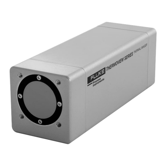
® ThermoView TV30 Series Users Manual, Rev. 1.0, May 2023 1 Description The TV30 cameras define a new class of high-performance multi-product thermal imager, providing the models with a full complement of accessories with an IP67 environmental rating that can operate in the harshest environments. -
Page 15: Figure 1-1: Front And Rear View Of Tv30 Infrared Cameras
Description Available Models Figure 1-1: Front and Rear View of TV30 Infrared Cameras Protective Window (replacable) Status 1 Gbit/s Ethernet PoE M12 connector, 8 pin DIN M16 Connector, 12 pin... -
Page 16: Available Models
® ThermoView TV30 Series Users Manual, Rev. 1.0, May 2023 1.1 Available Models The following TV30 model variants are available. Figure 1-2: Available Models Model Temp Range IR Resolution Lens Interface Remark TV33 SA -10 to 1300°C 320 x 240 30°... -
Page 17: System Architecture
Description System Architecture 1.2 System Architecture Figure 1-3: Principal System Architecture for TV30 SA Camera OPC UA SCADA/HMI MQTT External I/O TV30 SA Camera Processing Unit (PLC) Internal I/O... -
Page 18: Technical Data
® ThermoView TV30 Series Users Manual, Rev. 1.0, May 2023 2 Technical Data 2.1 Measurement Specification Temperature Range -10 to 1300°C (14 to 2372°F) indication starting at -20°C (-4°F) Sub range 1: -10 to 100°C (14 to 212°F) Sub range 2: 20 to 250°C (68 to 482°F) Sub range 3: 200 to 1300°C (392 to 2372°F) -
Page 19: Optical Specifications
Technical Data Optical Specifications 2.2 Optical Specifications The following optical specification is based on the theoretical calculated spot size derived on the pitch of the camera detector array and the lens focal length. The Instantaneous Field of View (IFOV) specifies the size of the image of an individual detector element in the object plane assuming ideal imaging optics. -
Page 20: Wide Angle Lens
® ThermoView TV30 Series Users Manual, Rev. 1.0, May 2023 2.2.2 Wide Angle Lens Field of View (FOV) 48° x 36° (horizontal x vertical) 100 mm to ∞ (3.9 in to ∞) Focus Range TV33 IFOV 2.6 mrad MFOV 7.9 mrad TV36 IFOV 1.3 mrad... -
Page 21: Electrical Specifications
Technical Data Electrical Specifications 2.3 Electrical Specifications Power 24 VDC, ± 20%, max 15 W (via M16 socket) ≤ 500 mV (peak-to-peak) Residual ripple Power over Ethernet IEEE 802.3at, mode A or B, mixed DC & data Ethernet Connection M12 socket, 8 wires (full duplex) 10/100/1000 Mbit/s, 1000BASE-TX, Auto-Negotiation electrically isolated from power supply multi-color indicator, see section 6.2... -
Page 22: Communications
® ThermoView TV30 Series Users Manual, Rev. 1.0, May 2023 2.4 Communications Protocols TCP/IP version 4 mDNS (Multicast DNS/Bonjour) HTTPS (Hypertext Transfer Protocol Secure) SSDP (Simple Service Discovery Protocol) NTP (Network Time Protocol) MQTT OPC UA (OPC Unified Architecture) Addressing static IP address (factory default) DHCP Auto IP (address range 169.254.0.0/16) -
Page 23: Dimensions
Technical Data Dimensions 2.6 Dimensions Figure 2-1: Dimensions of ThermoView TV30 2.7 Scope of Delivery The scope of standard delivery includes the following: ThermoView TV30 camera Printed version of Safety Data Sheet & Quickstart The user manual is available as download on the following web site: www.flukeprocessinstruments.com/en-us/downloads/product-manuals... -
Page 24: Basics
® ThermoView TV30 Series Users Manual, Rev. 1.0, May 2023 3 Basics 3.1 Measurement of Infrared Temperature All surfaces emit infrared radiation. The intensity of this infrared radiation changes according to the temperature of the object. Depending on the material and surface properties, the emitted radiation lies in a wavelength spectrum of approximately 1 to 20 µm. -
Page 25: Environment
Environment Ambient Temperature 4 Environment 4.1 Ambient Temperature Without water cooling, the TV30 camera is designed for ambient operating temperatures between -10 to 50°C (14 to 122°F). With water cooling equipment, it can be used in environments at higher temperatures. By forcing water circulation, it is possible to maintain cooled internal housing temperatures. -
Page 26: Installation
® ThermoView TV30 Series Users Manual, Rev. 1.0, May 2023 5 Installation Risk of Personal Injury When this instrument is being used in a critical process that could cause property damage and personal injury, the user should provide a redundant device or system that will initiate a safe process shutdown in the event that this instrument should fail. -
Page 27: Powering
Installation Powering mounting to provide the required alignment accuracy. Avoiding or removing physical mounting limitations and obstructions in the camera’s optical path, may also be required. 5.5 Powering 5.5.1 Power over External Supply In case the camera is not supplied with power via Ethernet PoE, power can also be supplied using the 12-wire cable. -
Page 28: Power Over Ethernet
® ThermoView TV30 Series Users Manual, Rev. 1.0, May 2023 5.5.2 Power over Ethernet The camera is supplied with power via the PoE (Power over Ethernet) following the IEEE 802.3at standard. PoE allows a single cable to provide both data connection and electric power to the sensor. The following figure shows exemplarily the connection to a computer or a non-PoE switch. -
Page 29: Connecting
Installation Connecting Figure 5-4: Connecting the Ethernet M12 Cable to the Camera Ethernet cables offered by the manufacturer can be found as electrical accessories, see section 8.1.1 Ethernet PoE Cable (A-CB-xx-M12-W08-xx), page 57. For dedicated PoE injectors are offered by the manufacturer, see section 8.1.7 PoE Injector (A-TV-POE1), page 65, and 8.1.8... -
Page 30: Digital Inputs
® ThermoView TV30 Series Users Manual, Rev. 1.0, May 2023 Table 5-1: Pin Assignment for DIN Connector Connector Pin TV30 SA + 24 VDC GND Power Input 1 Input 2 Input 3 GND Input Output 1 Output 2 Output 3 GND Output n.a. -
Page 31: Figure 5-7: Digital Output Using Pull-Up
Installation Connecting Figure 5-7: Digital Output using Pull-Up +5 VDC Camera Isolation Output 1 (J) max I = 7 mA source GND Output (K) Figure 5-8: Digital Output using Open-Drain 24 VDC max Camera Isolation Output 1 (J) max I = 100 mA sink GND Output (K) -
Page 32: Operation
® ThermoView TV30 Series Users Manual, Rev. 1.0, May 2023 6 Operation 6.1 Getting Started Find below the first basic steps to work with the camera: Powering Supply power to the camera either via Power over Ethernet (PoE) or directly via the 12-wire connector on the back of the housing, see section 5.5 Powering, page 27. -
Page 33: Shutter
Operation Shutter Please note that the camera displays these patterns in a priority order, higher numbered events mask lower numbered events. So, for example, the camera is connected to Ethernet (solid green) but have an over- temperature condition. In that case, the LED displays a solid red until the over-temp condition is cleared, then the LED would display solid green. -
Page 34: Web Server
® ThermoView TV30 Series Users Manual, Rev. 1.0, May 2023 7 Web Server Several information of the camera is available and will be displayed using a standard web browser. Furthermore, several settings can be initiated and transferred to the imager. It is possible to display or set the device IP address, to modify the focus of the infrared camera or to upload a new firmware. -
Page 35: Camera
Web Server Camera Pages 7.2 Camera Pages 7.2.1 <Camera> <Values> Figure 7-2: Values The camera uses analysis objects to present thermal information contained in an infrared image called AOI’s (area of interest). An AOI can be built using one of the tools on the left side of the page: ... -
Page 36: Figure 7-3: Values Selection
® ThermoView TV30 Series Users Manual, Rev. 1.0, May 2023 Figure 7-3: Values Selection Name describes the AOI via a name Emissivity defines the desired emissivity value specifically assigned to the AOI In case of overlapping pixels of several AOIs, the emissivity value of the last generated AOI is applied for these pixels. -
Page 37: Figure 7-4: Calculated Value
Web Server Camera Pages Clicking on the math symbol icon on the left side of the page opens the dialog for the calculated value. Figure 7-4: Calculated Value Name describes the Calculated Value via a name Value 1 defines the first operator for the calculation (e.g. Rect AOI) Value 2 defines the second operator for the calculation (e.g. -
Page 38: Camera>
® ThermoView TV30 Series Users Manual, Rev. 1.0, May 2023 7.2.2 <Camera> <Conditions> Figure 7-5: Conditions Condition is a state that must exists to activate a specific action. Most of the process control logic is defined by conditions. Conditions are universal, they can be used in different circumstances: alarm conditions, conditions that output temperature values and so on. -
Page 39: Figure 7-6: Measurement Condition
Web Server Camera Pages Figure 7-6: Measurement Condition Name defines the name of the condition Value The value can be provided from an AOI, a constant temperature value, or the internal device temperature. Operator Defines the comparison operation between the value and a fixed temperature. The logical operator is selectable between Greater Than or Less Than Output Output Type... -
Page 40: Figure 7-7: Combination Condition
® ThermoView TV30 Series Users Manual, Rev. 1.0, May 2023 Figure 7-7: Combination Condition Name defines the name of the combination Condition 1 refers to the status of a predefined condition Condition 2 refers to the status of a predefined condition Operator links condition 1 and condition 2 with the logical operator AND or OR Output... -
Page 41: Camera>
Web Server Camera Pages 7.2.3 <Camera> <Configuration> Figure 7-8: Configuration Palette and Measurement Range In infrared images color of every pixel depends on its temperature. The TV30 camera has means to adjust this dependency to make visual appearance of the image better and to intensify important details. To set relation between colors and temperature you need to select color palette and define temperature range. - Page 42 ® ThermoView TV30 Series Users Manual, Rev. 1.0, May 2023 Focus The camera is equipped with a motorized focus. The focus setting is controlled by Autofocus Type. Autofocus Type <AOI> focus setting is applied to an exclusive AOI <Full Image> focus setting is applied to the whole infrared image <Manual>...
-
Page 43: Settings
Web Server Settings Pages Figure 7-9: Shutter Settings Enable Automatic Shutter enables/disables the automatic shutter Input to disable shutter links to an internal input of the camera or to a Wago input Input to activate shutter links to an internal input of the camera or to a Wago input True when value is “high”... -
Page 44: Settings>
® ThermoView TV30 Series Users Manual, Rev. 1.0, May 2023 Select User Switches between predefined users. <New User> adds a profile for a new user. User Type <Admin> - providing full privileges <Developer> - providing access to Home and Camera page <Viewer>... -
Page 45: Obtain Ip Address Via Dhcp / Auto Ip
Web Server Settings Pages 7.3.2.1 Obtain IP Address via DHCP / Auto IP Using DHCP In DHCP mode, connect the infrared camera to a network which has a DHCP server available. Typically, the router of your network runs a DHCP server, but this can also run in a server computer. Contact your network administrator for more information about your network setup. -
Page 46: Settings>
® ThermoView TV30 Series Users Manual, Rev. 1.0, May 2023 Figure 7-13: Networking 7.3.3 <Settings> <Localization> Figure 7-14: Localization Device Date/Time Use NTP Synchronization NTP is the default time synchronization method. It uses the router/modem in the network or the Google NTP server time.google.com Sync with Computer Time You can also synchronize the camera with the computer time. -
Page 47: Settings>
Web Server Settings Pages 7.3.4 <Settings> <Device Management> Figure 7-15: Device Management Name Camera Name Specifies a name for the camera. Reduced Resolution … Switches to the camera to a lower resolution. This could be helpful to reduce data traffic in a network. Calibration Download Statement of Downloads the statement calibration practices for the camera as a pdf file. -
Page 48: I/O
® ThermoView TV30 Series Users Manual, Rev. 1.0, May 2023 Firmware will be reset … Your firmware will be reset to factory state and all stored data will be removed/reverted. Firmware Update Firmware Update allows to install a new firmware version to the device. Contact the TechSupport team for getting latest firmware file available. -
Page 49: I/O>
Web Server I/O Pages 7.4.2 <I/O> <External> Figure 7-17: WAGO Module Wago Enabled Enables the support of the camera for the Wago IO modules. Fieldbus Coupler Address Specifies the IP network address and the port for the fieldbus coupler. The fieldbus coupler is used to manage the WAGO IO modules, the Wago modules itself do not have individual IP addresses. - Page 50 ® ThermoView TV30 Series Users Manual, Rev. 1.0, May 2023 Number of digital outputs Shows the number of detected digital outputs. Pressing the Setting button opens the following dialog: Output: selects the desired digital output Inverted: inverts the digital data at the digital output so that 0 becomes 1 or 1 becomes 0.
-
Page 51: I/O>
Web Server I/O Pages 7.4.3 <I/O> <MQTT> MQTT is a communication protocol in a server-client architecture. After the connection is established, the TV30 camera as a publisher (MQTT client) sends messages to the broker (MQTT server). A message always consists of the message content and a topic. - Page 52 ® ThermoView TV30 Series Users Manual, Rev. 1.0, May 2023 MQTT Enabled Enables the TV30 camera as publisher (MQTT client). Broker Address Enter the IP address of the MQTT broker to which the TV30 camera should connect as publisher. Broker Port Enter the communication port of the desired MQTT broker.
-
Page 53: I/O>
Web Server I/O Pages 7.4.4 <I/O> <OPC UA> OPC UA (OPC Unified Architecture) is a standard for platform-independent data exchange for the industrial communication. Figure 7-20: Principle of OPC UA Network OPC UA Client OPC UA Client Cloud OPC UA Server TV30 Camera OPC UA Client OPC UA Client... -
Page 54: Table 7-2: Opc Ua Items
® ThermoView TV30 Series Users Manual, Rev. 1.0, May 2023 Table 7-2: OPC UA Items Device Item Access Format Comments ThermoView- read Device name. If the user does not assign a name to the camera, the serial <name> number is used for <name>. Example: ThermoView-59280004 emissivity read/write double Global emissivity in the standard range 0.01 …... - Page 55 Web Server I/O Pages Device Item Access Format Comments deviceStatus read UInt32 Error status of the camera 0 = no error Bit 0: Cali param/mats error Bit 1: Mfg param error Bit 2: Parameter store error Bit 3: Engine I2C error Bit 4: Engine video open error Bit 5: Engine video data error Bit 6: Focus motor error...
-
Page 56: Accessories
® ThermoView TV30 Series Users Manual, Rev. 1.0, May 2023 8 Accessories A full range of accessories for various applications and industrial environments are available. Accessories include items, that may be ordered at any time and added on-site. 8.1 Electrical Accessories The following electrical accessories are available: ... -
Page 57: Ethernet Poe Cable (A-Cb-Xx-M12-W08-Xx)
Accessories Electrical Accessories 8.1.1 Ethernet PoE Cable (A-CB-xx-M12-W08-xx) The Ethernet PoE cable comes with an eight-pin male M12 connector, assigned to the cameras rear eight-socket female M12 connector. The corresponding end of the Ethernet PoE cable is equipped with a general RJ45 snap- in connector. -
Page 58: 12-Wire Cable, High Temp (A-Cb-Ht-M16-W12-Xx)
® ThermoView TV30 Series Users Manual, Rev. 1.0, May 2023 8.1.2 12-Wire Cable, High Temp (A-CB-HT-M16-W12-xx) Use the High Temp 12-wire cable for the camera to support power supply and all inputs and outputs. The cable described below is a shielded 12-conductor cable, made of two twisted pairs plus 8 separate wires, all as tinned copper braid. - Page 59 Accessories Electrical Accessories Risk of Personal Injury Teflon develops poisonous gasses when it is exposed to flames! Note An ordered cable does not include a terminal block! Note If you cut the cable to shorten it, notice that both sets of twisted-pair wires have drain wires inside their insulation. These drain wires (and the white wire that is not part of the twisted pair) must be connected to the terminal labeled CLEAR.
-
Page 60: 12-Wire Cable, Low Temp (A-Cb-Lt-M16-W12-Xx)
® ThermoView TV30 Series Users Manual, Rev. 1.0, May 2023 8.1.3 12-Wire Cable, Low Temp (A-CB-LT-M16-W12-xx) Use the Low Temp 12-wire cable for the sensor to support power supply, all inputs, outputs, and the RS485 interface. The cable described below is a shielded 12-conductor cable, made of two twisted pairs plus 8 separate wires, all as tinned copper braid. - Page 61 Accessories Electrical Accessories Risk of Personal Injury Polyurethane may cause allergy and possibly cancer! Note An ordered cable does not include a terminal block! Note If you cut the cable to shorten it, notice that both sets of twisted-pair wires have drain wires inside their insulation. These drain wires (and the white wire that is not part of the twisted pair) must be connected to the terminal labeled CLEAR.
-
Page 62: Terminal Block (A-Tv30-Tb)
® ThermoView TV30 Series Users Manual, Rev. 1.0, May 2023 8.1.4 Terminal Block (A-TV30-TB) The terminal block accessory is for the connection of the sensor to the customer’s industrial environment. It lists all different conductor colors on one side and the related signal names on the other side. Terminal Block with Wire Color Assignment Figure 8-5: to the Camera... -
Page 63: Ethernet Cable (A-Cb-Lt-Rj45-Xx)
Accessories Electrical Accessories 8.1.5 Ethernet Cable (A-CB-LT-RJ45-xx) The Ethernet cable comes with RJ45 connectors on both ends. Figure 8-6: Ethernet Cable Table 8-8: Ethernet Cables – Available Lengths Length A-CB-LT-RJ45-03 0.3 m (1 ft) A-CB-LT-RJ45-25 25 m (82 ft) -
Page 64: Fiber Optic Cable (A-Cb-Fo-Xxx)
® ThermoView TV30 Series Users Manual, Rev. 1.0, May 2023 8.1.6 Fiber Optic Cable (A-CB-FO-xxx) Use fiber optic communication for Ethernet cable runs beyond 90 m (295 ft). The cables are available in the following lengths: 150 m (492 ft), part number A-CB-FO-150 ... -
Page 65: Poe Injector (A-Tv-Poe1)
Accessories Electrical Accessories 8.1.7 PoE Injector (A-TV-POE1) The PoE Injector (A-TV-POE1) is intended to use in office environments. With PoE (Power over Ethernet), the injector transfers both data and electrical power to Ethernet-enabled devices using a standard CAT5 cable. The injector injects up to 30 W for the attached device(s). It operates at an ambient temperature up to 55ºC (131°F). -
Page 66: Poe Injector Industrial (A-Tv-Poe2)
® ThermoView TV30 Series Users Manual, Rev. 1.0, May 2023 8.1.8 PoE Injector Industrial (A-TV-POE2) The PoE Injector Industrial (A-TV-POE2) is intended to use in industrial environments. With PoE (Power over Ethernet), the injector transfers both data and electrical power to Ethernet-enabled devices using a standard CAT5 cable. -
Page 67: Power Supply Din Rail (A-Ps-Din-24V)
Accessories Electrical Accessories 8.1.9 Power Supply DIN Rail (A-PS-DIN-24V) The DIN-rail mount industrial power supply delivers isolated dc power and provides short circuit and overload protection. Risk of Personal Injury To prevent electrical shocks, the power supply must be used in protected environments (cabinets)! Technical data: Protection class... -
Page 68: Fiber Optic To Ethernet Converter (A-Con-Fo-Rj45)
® ThermoView TV30 Series Users Manual, Rev. 1.0, May 2023 8.1.10 Fiber Optic to Ethernet Converter (A-CON-FO-RJ45) The Fiber Optic Converter (A-CON-FO-RJ45) is an industrial Ethernet switch with 6 RJ45 GBit Ethernet ports and 2 multi-mode GBit fiber optic ports. The converter is DIN-rail or wall mountable. Communications Standard IEEE 802.3, 802.3u, 802.3ab, 802.3x, IEEE 802.3z... -
Page 69: Ethernet Switch (A-Con-Sw)
Accessories Electrical Accessories 8.1.11 Ethernet Switch (A-CON-SW) The Ethernet Switch (A-CON-SW) has 4 x 10/100/1000BASE-T Ethernet ports with PoE+ functionality and 2 x SFP sockets. It works within a wide operating temperature range. This switch can provide 30 W output per PoE port. -
Page 70: I/O Modules
® ThermoView TV30 Series Users Manual, Rev. 1.0, May 2023 8.1.12 I/O Modules The following I/O modules are available for the TV30 imager: Basic Kit (A-IO-BASICKIT), contains: Fieldbus Coupler 750-362, Supply Module 750-602, End Module 750-600 Digital Input Module 750-1406, 16 channels (A-IO-16DI) ... -
Page 71: Mechanical Accessories
Accessories Mechanical Accessories 8.2 Mechanical Accessories The following mechanical accessories are available: Mounting Base (A-TV30-MB) Air Purge Collar (A-TV30-AP) Water Cooling Enclosure (A-TV30-AP-WC) Outdoor Enclosure (A-TV-ENCVW) Swivel Bracket (A-BR-S) Protective Windows (S-TV30-PW) -
Page 72: Mounting Base (A-Tv30-Mb)
® ThermoView TV30 Series Users Manual, Rev. 1.0, May 2023 8.2.1 Mounting Base (A-TV30-MB) The mounting base is to adapt the imager in an easy way to any kind of fixture. For the fixture to tripods or swivel brackets, the mounting base provides two standard ¼-20 UNC holes. Figure 8-9: Mounting Base Figure 8-10: Mounting Base Dimensions... -
Page 73: Figure 8-11: Assembling The Mounting Base
Accessories Mechanical Accessories Figure 8-11: Assembling the Mounting Base M4x10 (x4) Figure 8-12: Camera with Mounting Base... -
Page 74: Air Purge Collar (A-Tv30-Ap)
® ThermoView TV30 Series Users Manual, Rev. 1.0, May 2023 8.2.2 Air Purge Collar (A-TV30-AP) The air purge collar is used to keep dust, moisture, airborne particles, and vapors away from the lens. Air flows into the 1/8” NPT fitting and out the front aperture. Clean filtered (or “instrument”) air is recommended to avoid contaminants from settling on the lens. -
Page 75: Figure 8-15: Camera With Air Purge Collar And Mounting Base
Accessories Mechanical Accessories Figure 8-15: Camera with Air Purge Collar and Mounting Base... -
Page 76: Water Cooling Enclosure (A-Tv30-Ap-Wc)
® ThermoView TV30 Series Users Manual, Rev. 1.0, May 2023 8.2.3 Water Cooling Enclosure (A-TV30-AP-WC) The water cooling enclosure allows the camera to be used in high ambient temperatures with water cooling. Water is supplied at the inlet IN, circulates in the housing walls, cools the unit, and exits at the outlet OUT. The connections are given via 1/8”... -
Page 77: Figure 8-18: Enclosure Dimensions
Accessories Mechanical Accessories Figure 8-18: Enclosure Dimensions... -
Page 78: Assembling
® ThermoView TV30 Series Users Manual, Rev. 1.0, May 2023 8.2.3.1 Assembling Remove the M4x6 screws (x4) to detach the back plate. Remove the back plate. The tray attached to the back plate does not need to be taken apart. Insert the imager in the tray and secure it with the screws M4x10 (x4) from below. - Page 79 Accessories Mechanical Accessories Slide the assembled into the enclosure. Use the M4x6 screws (x4) to close the enclosure. If required, the water cooling enclosure can also be combined with the mounting base with screws M4x10 (x4), see section 8.2.1 Mounting Base (A- TV30-MB), page 72.
-
Page 80: Outdoor Enclosure (A-Tv-Encvw)
® ThermoView TV30 Series Users Manual, Rev. 1.0, May 2023 8.2.4 Outdoor Enclosure (A-TV-ENCVW) In case, the thermal imager must be mounted in outdoor environments, an outdoor enclosure ensures weatherproofed installations. It provides a high protection rate, a sunshield, and a temperature-controlled heater for cooler environments. -
Page 81: Installation
Accessories Mechanical Accessories Figure 8-20: Dimensions 8.2.4.2 Installation Note To avoid erroneous readings, ensure that the transmission of 0.87 for the built-in protective window (Germanium) must be set in the thermal imager! Note For installation / commissioning of the internal heating element be referred to the enclosed instructions of the manufacturer. - Page 82 ® ThermoView TV30 Series Users Manual, Rev. 1.0, May 2023 Push the housing cover upwards until the key on the housing cover snaps into the slot of the housing body. Remove the three hexagon socket screws on the back of the housing.
- Page 83 Accessories Mechanical Accessories Mount the sealing inner and the end cap to each cable. Pass all cables through the enclosure cable glands. Plug the connectors to the camera. Tight the end caps. Installation with PoE requires only one cable. Close the unused cable gland with the enclosed sealing body.
- Page 84 ® ThermoView TV30 Series Users Manual, Rev. 1.0, May 2023 Remount the rear lid onto the enclosure.
-
Page 85: Swivel Bracket (A-Br-S)
Accessories Mechanical Accessories 8.2.5 Swivel Bracket (A-BR-S) The swivel bracket is to mount the camera in a moveable position, to correct in an easy way the pitch and yaw orientation. For a correct imager orientation, you can pitch (0° – 90°) and swivel (0° - 360°) the imager sighting axis. -
Page 86: Figure 8-23: Camera With Swivel Bracket
® ThermoView TV30 Series Users Manual, Rev. 1.0, May 2023 Figure 8-23: Camera with Swivel Bracket... -
Page 87: Protective Windows (S-Tv30-Pw)
Accessories Mechanical Accessories 8.2.6 Protective Windows (S-TV30-PW) The protective window protects the camera’s inner parts against dust and other contamination. The window is integrated directly into the front end of the camera. It is available as spare part. Figure 8-24: Protective Window... -
Page 88: Maintenance
® ThermoView TV30 Series Users Manual, Rev. 1.0, May 2023 9 Maintenance Our sales representatives and customer service staff are always at your disposal for questions regarding applications, calibration, repair, and solutions to specific problems. Please contact your local sales representative if you need assistance. -
Page 89: Troubleshooting
Maintenance Troubleshooting 9.2 Troubleshooting Table 9-9: Troubleshooting Symptom Probable cause Remedy Power does not turn on. Power switch is not on. Turn on the Power Switch. AC adapter is not connected. Connect AC adapter. Measuring temperature is in error. Wrong emissivity is set Set correct emissivity. -
Page 90: Cleaning The Window
® ThermoView TV30 Series Users Manual, Rev. 1.0, May 2023 9.3 Cleaning the Window Always keep the window clean. Care should be taken when cleaning the window. To clean the window, do the following: Lightly blow off loose particles with “canned” air (used for cleaning computer equipment) or a small squeeze bellows (used for cleaning camera lenses). -
Page 91: Appendix
Appendix Field of View Calculator 10 Appendix 10.1 Field of View Calculator It is important that the TV30 camera is mounted at a distance from the target, sufficient to be able to “see” the entire area of interest. For this reason, the manufacturer provides a field of view calculating software called “Spot Size Calculator”, which allows the calculation of the thermal image size (Field of View FOV) and the pixel size (Instantaneous Field of View IFOV) for a given lens, based on a specific camera mounting distance. -
Page 92: Avoidance Of Condensation
® ThermoView TV30 Series Users Manual, Rev. 1.0, May 2023 10.2 Avoidance of Condensation If environmental conditions make water cooling necessary, it is strictly recommended to check whether condensation will be a real problem or not. Water-cooling also causes a cooling of the air in the inner part of the sensor, thereby decreasing the capability of the air to hold water. -
Page 93: Determination Of Emissivity
Appendix Determination of Emissivity 10.3 Determination of Emissivity Emissivity is a measure of an object’s ability to absorb and emit infrared energy. It can have a value between 0 and 1.0. For example, a mirror has an emissivity of < 0.1, while the so-called blackbody reaches an emissivity value of 1.0. - Page 94 ® ThermoView TV30 Series Users Manual, Rev. 1.0, May 2023 Table 10-1: Typical Emissivity Values for Metals Material 8 – 14 µm Aluminum Unoxidized 0.02-0.1 Oxidized 0.2-0.4 Alloy A3003, Oxidized Roughened 0.1-0.3 Polished 0.02-0.1 Brass Polished 0.01-0.05 Burnished Oxidized Chromium 0.02-0.2 Oxidized Copper...
- Page 95 Appendix Typical Emissivity Values Material 8 – 14 µm Monel (Ni-Cu) 0.1-0.14 Oxidized 0.7-0.9 Nickel Oxidized 0.2-0.5 Electrolytic 0.05-0.15 Platinum Black Silver 0.02 Steel Cold-Rolled 0.7-0.9 Ground Sheet 0.4-0.6 Polished Sheet Molten Oxidized 0.7-0.9 Stainless 0.1-0.8 Tin (Unoxidized) 0.05 Titanium Polished 0.05-0.2 Oxidized...