Table of Contents
Advertisement
Quick Links
Guard Lock Safety-door Switch
D4NL
Lead-free, Environment-
friendly Design
• Contains no harmful substances, such as lead or
cadmium, reducing the burden on the environ-
ment.
• Models with 4-contact and 5-contact built-in
switches are available.
• Key holding force of 1,300 N min.
• Can be used for either standard loads or micro-
loads.
• Lineup includes models with a conduit size of M20.
• IP67 degree of protection.
Model Number Structure
Model Number Legend
Switch
D4NL-@@@@-@@@
1 2 3 4
5 6 7
1. Conduit Size
1:
Pg13.5
2:
G1/2
4:
M20
2. Built-in Switch (with Door Open/Closed Detection Switch and
Lock Monitor Switch Contacts)
A:
1NC/1NO slow-action contacts plus 1NC/1NO slow-action
contacts
B:
1NC/1NO slow-action contacts plus 2NC slow-action con-
tacts
C:
2NC slow-action contacts plus 1NC/1NO slow-action con-
tacts
D:
2NC slow-action contacts plus 2NC slow-action contacts
E:
2NC/1NO slow-action contacts plus 1NC/1NO slow-action
contacts
F:
2NC/1NO slow-action contacts plus 2NC slow-action con-
tacts
G:
3NC slow-action contacts plus 1NC/1NO slow-action con-
tacts
H:
3NC slow-action contacts plus 2NC slow-action contacts
3. Head Mounting Direction and Material
F:
Four mounting directions possible (Front-side mounting at
time of delivery)/plastic
D:
Four mounting directions possible (Front-side mounting at
time of delivery)/metal
4. Door Lock and Release
A:
Mechanical lock/24-VDC solenoid release
B:
Mechanical lock/110-VAC solenoid release
C:
Mechanical lock/230-VAC solenoid release
G:
24-VDC solenoid lock/mechanical release
H:
110-VAC solenoid lock/mechanical release
J:
230-VAC solenoid lock/mechanical release
D4NL
5. Indicator
B:
10 to 115 VAC/VDC (orange LED indicator)
6. Release Key Type
Blank:Standard
4:
Special release key
7. Release Key Position
Blank:Bottom
S:
Front
Operation Key
D4DS-K@
1
1. Operation Key Type
1:
Horizontal mounting
2:
Vertical mounting
3:
Adjustable mounting (horizontal)
5:
Adjustable mounting (horizontal/vertical)
\
1
Advertisement
Table of Contents

Related Manuals for Omron D4NL-4AFA-B4


Summary of Contents for Omron D4NL-4AFA-B4
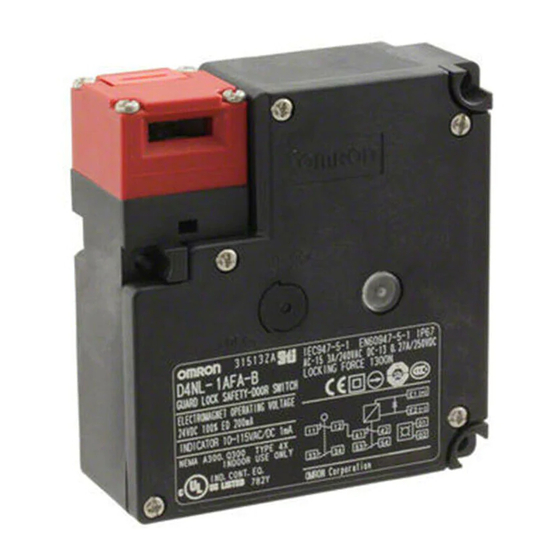
- Page 1 Guard Lock Safety-door Switch D4NL Lead-free, Environment- friendly Design • Contains no harmful substances, such as lead or cadmium, reducing the burden on the environ- ment. • Models with 4-contact and 5-contact built-in switches are available. • Key holding force of 1,300 N min. •...
-
Page 2: Ordering Information
Ordering Information List of Models Switches (Operation Keys are sold separately.) : Models with approved direct opening contacts. Head Release Release Solenoid voltage/ Lock and release types Contact configuration Conduit opening Model material key type indicator (door open/closed position detection switch and lock monitor switch contacts) (slow-action) Approved direct opening... - Page 3 NC contact Plastic Bottom Special Solenoid: 24 VDC Mechanical lock 1NC/1NO+1NC/1NO Pg13.5 D4NL-1AFA-B4 release Orange LED: 10 to 115 Solenoid release G1/2 D4NL-2AFA-B4 VAC/VDC D4NL-4AFA-B4 1NC/1NO+2NC Pg13.5 D4NL-1BFA-B4 G1/2 D4NL-2BFA-B4 D4NL-4BFA-B4 2NC+1NC/1NO Pg13.5 D4NL-1CFA-B4 G1/2 D4NL-2CFA-B4 D4NL-4CFA-B4 2NC+2NC Pg13.5 D4NL-1DFA-B4...
-
Page 4: Operation Keys
UL508, CSA C22.2 No.14 E76675 voltage Make Break Make Break Note: 1. Consult your OMRON representative for details. 120 VAC 10 A 60 A 7,200 VA 720 VA 2. Approval for CSA C22.2 No. 14 is authorized by the UL 240 VAC 30 A mark. - Page 5 Characteristics Degree of protection (see note 2) IP67 (EN60947-5-1) (This applies for the Switch only. The degree of protection for the key hole is IP00.) Durability Mechanical 1,000,000 operations min. (see note 3) Electrical 500,000 operations min. for a resistive load of 3 A at 250 VAC (see note 4) Operating speed 0.05 to 0.5 m/s Operating frequency...
- Page 6 Connections Indicator Internal Circuit Diagram 10 to 115 VAC/VDC Constant-current diode Circuit Connection Example • Terminals 12 and 41 are connected internally and so connect termi- nals 11 and 42 for safety-circuit input. (GS-ET-19) • Connect terminals 21 and 22 and terminals 51 and 52 in series when using as safety-circuit input (redundancy circuit for terminals 11 and 12 and terminals 41 and 42 above).
-
Page 7: Operation Method
Operation Method Operation Principles Mechanical Solenoid Operation Key lock models When the Operation Key is inserted, it is The solenoid is released only when the Spring locked by the lock spring. The door will stay lock is turned ON. Lock plate locked even if there is a power interruption. - Page 8 Contact Form Indicates conditions where the Key is inserted and the lock is applied. Terminals 12 and 41 are connected internally (as per GS-ET-19). Model Contact Contact form Operating pattern Remarks D4NL-@AF@-@ 1NC/1NO + 1NC/ Lock position Only NC contacts 11- 12 and 41-42 have an 11-42 approved direct...
- Page 9 Dimensions Note: All units are in millimeters unless otherwise indicated Switches D4NL-@@@@-B Operating D4NL-@@@@-B 15.5 characteristics 30.5 Key insertion force 15 N max. Key extraction 30 N max. Pre-travel distance force Four, head mounting screws Black Operation Key 15.3 Pre-travel distance 9 mm max.
- Page 10 D4NL-@@@@-BS Operating D4NL-@@@@-BS 15.5 characteristics 30.5 Key insertion force 15 N max. Pre-travel distance Key extraction 30 N max. force Four, head mounting screws Black 15.3 Operation Key Pre-travel distance 9 mm max. Three, 4.3-dia. holes 10.5 Movement before 3 mm min. being locked Release key ±0.2...
- Page 11 With Operation Key Inserted D4NL + D4DS-K1 D4NL + D4DS-K2 Horizontal Horizontal insertion radius: insertion radius: Black R ≥ 200 Black R ≥ 200 44 min 46.5 max 40 min 42.5 max Key insertion position Key insertion position (30.5) (30.5) Center Center tolerance of...
-
Page 12: Application Examples
Application Examples G9SA-321-T@ (24 VAC/VDC) + D4NL-@@@A-@, @@@B-@, @@@C-@ (Mechanical Lock Type) + D4D-@520N Circuit Diagram Lock release signal Safety Limit Switch with direct opening mechanism (D4D) Guard Lock Safety-door Switch Reset switch Lock release switch KM1 and KM2: Magnetic Contactor 3-phase motor Feedback loop OPEN... - Page 13 G9SA-301 (24 VAC/VDC) + D4NL-@@@G-@, @@@H-@, @@@J-@ (Solenoid Lock Type) + D4D-@520N Circuit Diagram Lock signal Note: Lock release is possible at any time. Therefore, do not use the solenoid lock type in applications where the operator may be exposed to danger when the guard opens. Use the mechanical lock type instead.
-
Page 14: Safety Precautions
Precautions Release Key !Caution Do not insert the Operation Key with the door open. The machine UNLOCK may operate and damage may result. !Caution LOCK Do not use metal connectors or conduits with this switch. Damage • The release key is used to unlock the Switch in case of emergency to the broken conduit hole may cause electric shock. -
Page 15: Correct Use
Before applying the Switch, test it under actual operating con- ditions and be sure to use it at a switching frequency that will not • Use the designated OMRON Operation Key with the Switch. Using lower its performance. another Operation Key may result in Switch damage. -
Page 16: Recommended Connectors
Terminal screw • Do not touch the solenoid. The temperature of the solenoid increases when current is passed. • In conditions requiring greater rigidity, sealing performance, and oil resistance, use OMRON’s D4BL. Crimp terminal • Perform regular inspections. Conduit Opening •... -
Page 17: Product Replacement
Production Termination Dimensions Following the release of the D4NL, production of the D4DL will be terminated. Discon- tinued 15.5 Date of Production Termination Model 30.5 (D4DL) Production of the D4DL Series will be terminated in November 2003. Cap head Operation Key 15.3 Three, 4.3-dia. - Page 18 List of Recommended Substitute Products Switch D4DL product Recommended substitute product D4DL-1CFA-B D4NL-1AFA-B, D4NL-1BFA-B D4DL-2CFA-B D4NL-2AFA-B, D4NL-2BFA-B D4DL-1DFA-B D4NL-1CFA-B, D4NL-1DFA-B D4DL-2DFA-B D4NL-2CFA-B, D4NL-2DFA-B D4DL-1CFG-B D4NL-1AFG-B, D4NL-1BFG-B D4DL-2CFG-B D4NL-2AFG-B, D4NL-2BFG-B D4DL-1DFG-B D4NL-1CFG-B, D4NL-1DFG-B D4DL-2DFG-B D4NL-2CFG-B, D4NL-2DFG-B D4DL-1CFB-B D4NL-1AFB-B, D4NL-1BFB-B D4DL-2CFB-B D4NL-2AFB-B, D4NL-2BFB-B D4DL-1DFB-B D4NL-1CFB-B, D4NL-1DFB-B D4DL-2DFB-B...
- Page 19 D4NL...
- Page 20 Cat. No. C126-E1-01 In the interest of product improvement, specifications are subject to change without notice. OMRON EUROPE B.V. Wegalaan 67-69, NL-2132 JD, Hoofddorf, The Netherlands Phone: +31 23 568 13 00 Fax: +31 23 568 13 88 www.eu.omron.com Safety Sensors / Components...