Advertisement
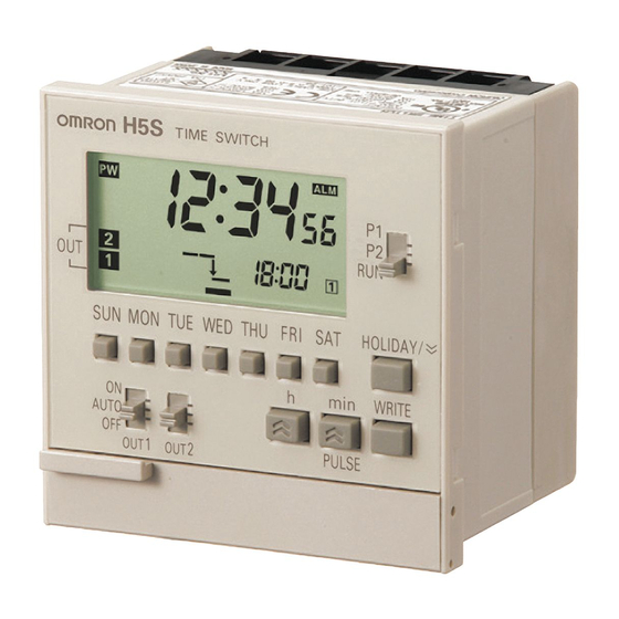
Digital Time Switch
H5S
Easier, More Convenient Time Switches, with
New 4-circuit Output and Yearly Models in
Addition to 2-circuit Weekly Models
• Independent Day Keys provide easier operation.
• Temporary holiday setting function makes it easy to turn OFF output
for holidays and non-operating days.
• Settings can be made even with the Time Switch turned OFF.
• Test mode enables easy program checking.
• Complies with EMC Directives, UL/CSA, and other safety standards.
• Includes summer time (DST) adjustment.
Yearly models also offer automatic switching to DST.
• Set value can be changed both upward and downward for speedier
setting.
• Integrated temperature compensation circuit helps keep accurate
time over a wide temperature range. (See note 1.)
• Includes time counter and total counter functions with alarm indicator.
(See note 2.)
• Bank function allows program switching by an external input. (See
note 3.)
• New 4-circuit output models with a compact, 72 × 72-mm DIN size
added to the series.
Note: 1. Available only on yearly models.
2. Available only on 2-circuit models.
3. Available only on weekly models.
Features
Easier and More Convenient to Use
■ Simple Setting
Independent Day Keys make setting easy.
■ Convenient Functions
Time Counter/Total Counter Functions (See note.)
This function makes it possible to monitor the total time that a load
has been applied, or the total number of operating cycles. It allows
the Time Switch to be used for managing maintenance.
With alarm indicator
Up/down set value changing
for speedy setting.
Temporary holidays
(non-operating days)
are also easy to set.
Weekly models: Specify the day.
Yearly models: Specify the date.
Shows total lamp ON time
Time Adjustment Function (See note.)
The time can be set to 00 min 00 s by using an external input. The
times on multiple Time Switches can also be easily synchronized.
Synchronized!
Slave
Master
Note: Equipped on 2-circuit models.
Digital Time Switch
Slave
H5S
1
Advertisement
Table of Contents

Related Manuals for Omron H5S


Summary of Contents for Omron H5S
- Page 1 ■ Simple Setting Time Adjustment Function (See note.) The time can be set to 00 min 00 s by using an external input. The Independent Day Keys make setting easy. times on multiple Time Switches can also be easily synchronized.
-
Page 2: Model Number Structure
Model Number Structure ■ Model Number Legend Note: This model number legend includes combinations that are not available. Please check the “List of Models” for availability. H5S- @@@@@ - @ 1 2 3 4 5 1. -
Page 3: Ordering Information
Note: 1. Do not use inverter output as a power supply. For details, refer to Precautions for Safe Use, item 24, on page 12. 2. The capacity is 15 A per circuit, but derating of the total current for two circuits is required as shown below depending on the ambient temperature. - Page 4 Influence of temperature ± 15 s per month (at 25 ° C) ± 15 s per month (at − 10 to 45 ° C), ± 20 s per month (at 45 to 55 ° C) Cyclic error Continuous use: 5 years min. (at 25 ° C) (See note 2.) Memory protection 100 M Ω...
- Page 5 For details, refer to Day Override Operation on page 21. Program check Consecutively displays the days and times when the output is set to turn ON and OFF over the course of one week in the sequence in which the Time Switch is to operate.
- Page 6 Yearly 2-circuit Models (H5S-Y@2) Yearly 4-circuit Models (H5S-Y@4) Checking the Consecutively displays the times when the output is set to turn ON and OFF for one day in the sequence in which the Time settings Switch is to operate. For details, refer to Checking the Settings on page 21.
- Page 7 Use a contact that is capable of operating with 5 V, 0.1 A (with a minimum signal input width of 100 ms). Flush mounting models (H5S-@A2@/-@B2@) Surface mounting models (H5S-@FA2@/-@FB2@) Note: Input must be selected using the “F2: Input selection” step of initial setting mode. For details, refer to Using Advanced Functions on page 23. Digital Time Switch...
-
Page 8: Key Operations
• Used to set the current day, operating day, etc. 1. Mode • Used to specify the date (yearly models only) Switch • In RUN mode, these keys are used to shift the Time Switch to the Checking the Settings mode. 2. Holiday/ 13. Day Keys... -
Page 9: Display Description
13. Holiday indicator Lit during setting a yearly program. Flashes during the Time Adjustment mode. Displays the current day or the day set for an (Yearly 4-circuit models) operation. 4. Main display Displays the number of the circuit (output) for 3. - Page 10 (Order separately) 2. Using a PFP-100N2 Mounting Track. Use a tool such as long nose pliers to prepare the openings for pulling wires. Note: 1. The terminal screws are M3.5. 2. This illustration shows a 2-circuit model. The 4-circuit model has the same dimensions.
- Page 11 PFP-100N2 PFP-50N ±0.15 ±0.3 ±0.15 ±0.3 29.2 15 (5) * 1,000 (500) * 1,000 * The numbers in parentheses ( ) are dimensions for the PFP-50N End Plate Spacer PFP-M PFP-S M4 × 8 pan-head screw 34.8 35.5 35.3 44.3 11.5...
-
Page 12: Safety Precautions
13.Do not connect more than two crimp terminals to each Time Switch terminal. Minor injury due to explosion may occasionally occur. Do 14.Up to two wires of the same size and type can be inserted into a not use the product where subject to flammable or single terminals. -
Page 13: Basic Use
Ball-pressure test temperature (enclosure material): 125°C Basic Use Prior to Using Before setting the parameters necessary for each operation, the operation of each circuit (output) must be determined. Begin by setting initial setting mode as required. Open the front cover. - Page 14 Weekly, 2 Circuits Yearly, 2 Circuits Yearly, 4 Circuits Example: Set the current time to Saturday 17:28. Example: Set the current time to 17:28 on August 15, 2006. 1. Set the Mode 1. Set the Mode Switch to RUN. Shaded portion indicates Switch to RUN.
- Page 15 WRITE in program setting mode. • When the Mode Switch is set to P1 or P2 (to PRGM for 4-circuit models), the Time Switch stops automatic operation. To forcibly turn ON or OFF the output, use the Output ON/OFF Switches.
- Page 16 WRITE in program setting mode. • When the Mode Switch is set to P1 or P2 (to PRGM for the 4- circuit model), the Time Switch stops automatic operation. To forcibly turn ON or OFF the output, use the Output ON/OFF switches.
- Page 17 WRITE in program setting mode. repeatedly from 8:00 to 19:00 on Sunday. • When the Mode Switch is set to P1 or P2 (to PRGM for 4-circuit models), the Time Switch stops automatic operation. To forcibly Start Stop turn ON or OFF the output, use the Output ON/OFF Switches.
- Page 18 Yearly, 2 Circuits Yearly, 4 Circuits Yearly, 2 Circuits Yearly, 4 Circuits Yearly programs in addition to ordinary weekly programs can be set Partial clearing for 2- and 4-circuit yearly models. 1. Set the Mode Switch to P1 or P2 and...
- Page 19 1 s → 2 s → ··· 59 s → 1 m → ··· 59 m → 60 m → 1 s 7. Press WRITE to enter the settings. *1 If one or more programs have already been set, the display starts showing the 7. Press WRITE to enter the settings. set programs.
-
Page 20: Convenient Functions
(non-operating days). The Time Switch then operates according to the ordinary Example: The days from April 29 to May 7 in 2006 are set as (previous) settings from the following week onward. holidays (non-operating days). The Time Switch then operates according to the ordinary (previous) settings from the following year onward. - Page 21 Yearly, 4 Circuits Weekly, 2 Circuits The days and times when output is set to turn ON and OFF over the Operation for one day can be temporarily (for only one week) course of one week can be displayed in the sequence in which the executed on another day.
- Page 22 Helps to cope with sudden schedule changes without having to Each time is pressed for 2 s or more in RUN mode, the current revise the existing program. This function allows ON/OFF states that time switches between 12-hour (AM/PM) and 24-hour display.
-
Page 23: Using Advanced Functions
Refer to the Instruction Manual enclosed with the H5S for details. This function displays the total elapsed time and total input count for an external input. Initial Setting Mode The alarm indicator can also be displayed if an alarm value has been set. Weekly, 2 Circuits Yearly, 2 Circuits... - Page 24 Yearly, 2 Circuits Weekly, 2 Circuits The time can be set to 00 min 00 s at the same time as external input Two groups (banks) of programs can be registered with the Time is applied. When using two or more Time Switches, their times can Switch.
- Page 25 - - - - - - - - - - Displays the next operation for circuit 1 only. only 2 - - - - - - - - - - Displays the next operation for circuit 2 only. only 3 - - - - - - - - - - Displays the next operation for circuit 3 only.
- Page 26 Summer Time Schedule Selection (F7) Yearly, 2 Circuits Yearly, 4 Circuits The time and date when the Time Switch automatically switches to and from summer time can be selected with reference to the following regions. Parameters Regions Summer time start...
- Page 27 Digital Time Switch...
-
Page 28: Warranty
CONTRACT, WARRANTY, NEGLIGENCE, OR STRICT LIABILITY. In no event shall the responsibility of OMRON for any act exceed the individual price of the product on which liability is asserted. IN NO EVENT SHALL OMRON BE RESPONSIBLE FOR WARRANTY, REPAIR, OR OTHER CLAIMS REGARDING THE...