Table of Contents
Advertisement
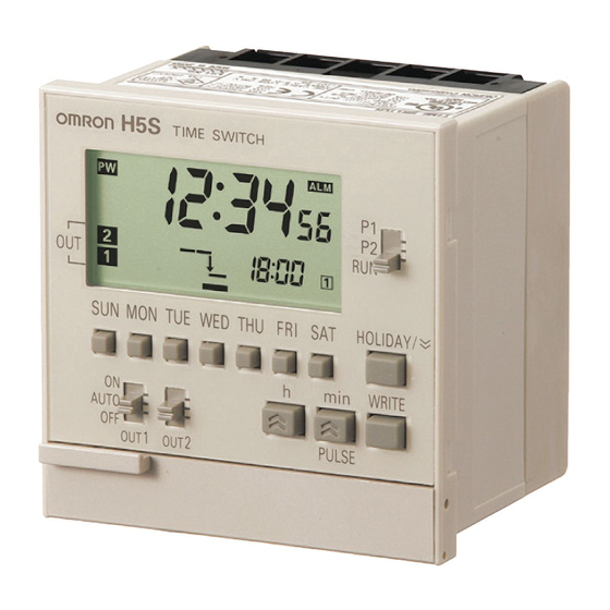
H5S
MODEL
DIGITAL TIME SWITCH
INSTRUCTION MANUAL
Thank you for purchasing this OMRON product.
Please read this instruction MANUAL and
thoroughly familiarize yourself with the functions
and characteristics of the product before use.
Please retain this MANUAL for future reference.
OMRON Corporation
© All Rights Reserved.
Safety Precautions
Table of Contents
Operation
Installation
9966572-0C
P.1
P.5
P.9
P.60
Advertisement
Table of Contents

Related Manuals for Omron H5S


Summary of Contents for Omron H5S
- Page 1 MODEL DIGITAL TIME SWITCH INSTRUCTION MANUAL Thank you for purchasing this OMRON product. Please read this instruction MANUAL and thoroughly familiarize yourself with the functions and characteristics of the product before use. Please retain this MANUAL for future reference. Safety Precautions...
-
Page 2: Suitability For Use
S u it abi li ty f or U s e OMRON shall not be responsible for conformity with any standards, codes, or regulations that apply to the combination of the products in the customer's application or use of the product. -
Page 3: Precautionary Information
Graphic symbol Warning against electric shock Notification of possible electric shock under certain conditions. General warning Notification of general, unspecified prohibition items. Prohibition against disassembly Notification of disassembly of products, when doing so can cause possible electric shock. General warning Notification of general, unspecified actions that users must perform. -
Page 4: Precautions For Safe Use
Precautions for Safe Use Please comply strictly with the following instructions which are intended to ensure safe operation of the controller. (1)Install the Time Switch only by qualified electrical workers. (2)Store the Time Switch within the specified ratings. If the Time Switch has been stored at temperatures -10˚C or lower, let it stand for 3 hours or longer at room temperature before turning ON the power supply. -
Page 5: Precautions For Correct Use
(17) Take adequate protective measures (such as a breaker, or fuse) for the power supply of the Time Switch. (18) When using heaters, be sure to use a thermal switch for the load circuit. (19) Always maintain the load current within specifications. (20) Use a switch, relay, or other contacts so that the rated power supply voltage will be reached within 0.1 s. -
Page 6: Table Of Contents
Table of Contents Suitability for Use Safety Precautions Precautionary Information Precautions for Safe Use Precautions for Correct Use Table of Contents How would you like to use the Time Switch? Operation 1. Operating Functions 2. Nomenclature 10.11.12 3. Time Adjustment 13.14 4. - Page 7 6. Advanced Operations 6-1. Total Time/Count Display 6-2. Time Adjustment Input Function 6-3. Manual Operation on Recovery from Power Failure 44 6-4. Bank Switching 6-5. Season Switching 6-6. Initial Setting Mode 6-6-1. F1: Next Operation Display 6-6-2. F2: Input Selection 6-6-3.
-
Page 8: How Would You Like To Use The Time Switch
How would you like to use the Time Switch? The H5S Time Switch offers simple operation to set various time controls. You want the Time Switch to turn an You want the Time Switch to turn output ON/OFF at a scheduled time. - Page 9 The H5S Time Switch has other convenient functions. You want the Time Switch to turn You want to monitor the periods for or OFF outputs on national holidays the times at which load is turned ON. or unscheduled holidays. The scheduled outputs are turned OFF...
-
Page 10: Operation
2 chnls 2 chnls 4 chnls The H5S, Digital Time Switch, has mainly three types. The main functions of these types are as shown in the following table. Operating functions are different depending on models. Please check the model and number, and read this manual thoroughly. -
Page 11: Nomenclature
2. Nomenclature Weekly Yearly Yearly 2 chnls 2 chnls 4 chnls <Front panel> <Weekly 2 chnls> MODE switch HOLIDAY/ DAY Keys HOLIDAY / DOWN Key WRITE Key WRITE OUT ON/OFF AUTO switches PULSE m/PLS Key OUT1 OUT2 h Key COPY TIMER RESET PULSE... - Page 12 2. Nomenclature Weekly Yearly Yearly 2 chnls 2 chnls 4 chnls <Front panel> <Yearly 2 chnls> MODE switch HOLIDAY/ DAY Keys HOLiDAY / DOWN Key m/PLS Key OUT ON/OFF WRITE Key AUTO switches WRITE m/PLS OUT1 OUT2 h Key TEST TIMER RESET PULSE...
- Page 13 2. Nomenclature Weekly Yearly Yearly 2 chnls 2 chnls 4 chnls <Front panel> <Yearly 4 chnls> MODE switch PRGM HOLIDAY/SELECT PRGM SELECT DAY Keys /DOWN Key PRGM m/PLS Key HOLIDAY OUT ON/OFF WRITE Key AUTO switches WRITE m/PLS OUT1 OUT2 OUT3 OUT4 h Key...
-
Page 14: Time Adjustment
3. Time Adjustment Weekly Yearly Yearly 2 chnls 2 chnls 4 chnls Example The current time (day/hour/minute) is set to Saturday 17:28. Set the Mode Switch to RUN. color indicates flashing. Press TIME ADJ for 2 s or more. symbol flashes. SUN MON TUE WED THU Press (The bar (... - Page 15 3. Time Adjustment Weekly Yearly Yearly 2 chnls 2 chnls 4 chnls Example The current time is set to 17:28 on August 15, 2006. Set the Mode PRGM Switch to RUN. color indicates flashing. 2 chnls 4 chnls Press TIME ADJ for 2 s or more.
-
Page 16: Basic Operations
4. Basic Operations 4-1. Ordinary Timer Operation Weekly Yearly Yearly 2 chnls 2 chnls 4 chnls Example The Time Switch turns ON circuit 1 or circuit 2 at 8:30 and turns it OFF at 17:15 from Monday through Friday. 8:30 17:15 8:30 17:15 8:30 17:15 8:30... - Page 17 Note • If multiple settings are required, repeat the steps through • Both the ON and OFF times must be set. • All the set weekly programs can be checked by pressing WRITE in program setting mode. • When the Mode Switch is set to P1 or P2 (to PRGM for 4 channel type), the Time Switch stop automatic operation.
-
Page 18: Multiple-Day Operation
4-2. Multiple-day operation Weekly Yearly Yearly 2 chnls 2 chnls 4 chnls Example1 The Time Switch turns circuit 1 or circuit 2 ON continuously between 8:30 on Monday and 17:15 on Friday. Number of remaining steps Set the Mode Switch to P1 or P2. color indicates flashing. - Page 19 Example 2 The Time Switch turns ON circuit 1 or circuit 2 at 22:00 from Monday through Friday and turns it OFF at 8:00 each following morning. 22:00 8:00 22:00 8:00 22:00 8:00 22:00 8:00 22:00 8:00 Number of remaining steps Set the Mode Switch to P1 or P2.
- Page 20 Weekly Yearly Yearly 2 chnls 2 chnls 4 chnls Example The Time Switch turns ON circuit 1 or circuit 2 for 30 seconds at 8:25 am from Monday through Saturday. AM8:25 Number of remaining steps Set the Mode Switch to P1 or P2. color indicates flashing.
- Page 21 Note • If multiple settings are required, repeat the steps through • Both the ON time and pulse width must be set. • All the set weekly programs can be checked by pressing WRITE in program setting mode. • When the Mode Switch is set to P1 or P2 (to PRGM for 4 channel type), the Time Switch stops automatic operation.
-
Page 22: Cyclic Operation
4-4. Cyclic Operation Weekly Yearly Yearly 2 chnls 2 chnls 4 chnls Example The Time Switch turns circuit 1 or circuit 2 ON for 5 minutes and OFF for 1 hour 55 minutes repeatedly from 8:00 to 19:00 on Sunday. Start Stop 5 min... - Page 23 Press WRITE Set the ON time period with SUN MON TUE WED THU Press WRITE Set the OFF time period with WRITE Press to confirm the settings. SUN MON TUE WED THU ⑧ Set the Mode Switch to RUN. 1 If one or more programs have already been set, the display starts showing the set programs. repeatedly until "-- : --"...
-
Page 24: Programming For The 4 Channel Type
2 and 4 channel yearly types. 22:15 Output performance of H5S If a weekly program and a yearly program overlap in operation time, the output of the H5S is continuously produced without being interrupted. - 23 -... -
Page 25: Yearly Timer Operation
4-7. Yearly Timer Operation Weekly Yearly Yearly 2 chnls 2 chnls 4 chnls Example 1 The Time Switch turns ON a circuit at 18:00 and turns it OFF at 22:15 on March 25 every year. Set the program in the following order. March 25 (Start date) Day period March 25 (End date) - Page 26 WRITE Press Specify the end date using If the starting year has been set to "--", the ending year cannot be set. Number of remaining steps Press WRITE Set the ON time with Press WRITE Set the OFF time with WRITE Press to confirm the settings.
- Page 27 8:00 (ON time) 12:00 (OFF time) 22:00 (OFF time) Output performance when no weekly programs are set on March 25 and April 9. 3/24/2006 3/25 3/26 Program 12 18 12 18 12 18 Program Output performance of H5S - 26 -...
-
Page 28: Yearly Pulse-Output Operation
4-8. Yearly Pulse-output Operation Weekly Yearly Yearly 2 chnls 2 chnls 4 chnls Example The Time Switch turns ON a circuit to operate for 2 minutes at 18:00 between March 25 and April 9. Set the program in the following order. March 25 (Start date) Day period April 9 (End date) - Page 29 WRITE Press Specify the end date using If the starting year has been set to "--", the ending year cannot be set. Number of remaining steps Press WRITE Set the ON time with WRITE The displayed pulse width changes by pressing this Key in the following order.
-
Page 30: Clearing The Settings
4-9. Clearing the Settings Weekly Yearly Yearly 2 chnls 2 chnls 4 chnls Example 1 Clearing a part of the settings. color indicates flashing. Set the Mode Switch to P1 or P2 and select a setting to be cleared. See Section 4-5 for 4 channel type. SUN MON TUE WED THU Give a short press on CLEAR... - Page 31 Example 2 Clearing all the settings of each circuit. color indicates flashing. Set the Mode Switch to the position of the circuit whose settings are to be cleared. See Section 4-5 for 4 channel type. SUN MON TUE WED THU Hold down CLEAR for 3 s or more.
-
Page 32: Convenient Functions
5. Convenient Functions 5-1. Setting (Temporary) Holidays (Weekly) Weekly Yearly Yearly 2 chnls 2 chnls 4 chnls Temporary holidays (non-operating days) can be set with ease. As the setting is automatically cleared after passing the days set as holidays, temporary holidays are easily set without changing the other settings including the output switches. - Page 33 Note • Any day in the 7-day period starting from the current day can be set as a holiday. The setting is automatically cleared after passing the days set as holidays. • All ON operations are cancelled on the holiday. •...
- Page 34 5-1. Setting (Temporary) Holidays (Yearly) Weekly Yearly Yearly 2 chnls 2 chnls 4 chnls Temporary holidays (non-operating days) can be set simply by specifying dates. As the setting is automatically cleared after passing the days set as holidays, temporary holidays are easily set without changing the other settings including the output switches.
-
Page 35: Setting (Temporary) Holidays 31
Note • Any date between the current date and December 31 in the year after the following year can be specified as a holiday. • The setting is automatically cleared after passing the dates set as holidays (unless the year is set to --). •... -
Page 36: Program Check Function
5-2. Program Check Function Weekly Yearly Yearly 2 chnls 2 chnls 4 chnls The set days and times when output turns ON and OFF over the course of one week can be displayed in the sequence the Time Switch is to operate. color indicates flashing. -
Page 37: Checking The Settings
5-3. Checking the Settings Weekly Yearly Yearly 2 chnls 2 chnls 4 chnls The set times for one day can be checked. color indicates flashing. Press one of the DAY keys for 2 s or more in run mode to check settings for the day. (“chec”... -
Page 38: Day Override Operation
5-4. Day Override Operation Weekly Yearly Yearly 2 chnls 2 chnls 4 chnls Operation for one day can be temporarily (for only one week) executed on another day. Example The operations set for Sunday is executed this Saturday. The Time Switch performs the ordinary operation (according to the previous settings) from next Saturday on. - Page 39 Note • Any day in the 7-day period starting from the current day can be set as a day on which another day's operations are to be executed. The setting is automatically cleared after passing the day. • Day override operation setting mode can be entered from run mode only. •...
-
Page 40: Summer Time (Dst) Adjustment (Manual)
5-5. Summer Time (DST) Adjustment (Manual) Weekly Yearly Yearly 2 chnls 2 chnls 4 chnls Each time is pressed for 2 s or more, the current time switches between the current time and the current time+1 hour. Note • The indicator is turned on during summer time. -
Page 41: Display Switching
5-7. Display Switching Weekly Yearly Yearly 2 chnls 2 chnls 4 chnls Each time is pressed for 2 s or more, the displayed content switches as shown below. Current time Total time Total count Next operation hour (Factory setting) Displays only when the input selection is set to “totl”. ( 6-6-2) 5-7. -
Page 42: Override And Automatic Return Operation
5-8. Override and Automatic Return Operation Weekly Yearly Yearly 2 chnls 2 chnls 4 chnls This function forcibly turns ON/OFF an output without changing the state of automatic operations. Example 1 Regular setting: ON at 9:00; OFF at 17:00 The Time Switch turns OFF an output at 15:00 today because of completing the production earlier than usual. - Page 43 Using override and automatic return operation for pulse-output operation Override and automatic return operation for pulse-output operation is as shown below. The operation procedure is the same as for timer operation. Example The Time Switch executes an override and automatic return operation when output is OFF.
-
Page 44: Advanced Operations
6. Advanced Operations 6-1. Total Time/Count Display Weekly Yearly Yearly 2 chnls 2 chnls 4 chnls This function displays the total elapsed time and total count of external inputs. If the upper limit of the total time or the total count is set, it is also possible to display the alarm indicator. -
Page 45: Time Adjustment Input Function
Yearly Yearly 2 chnls 2 chnls 4 chnls After power is restored to the H5S, it is possible to set the Time Switch to stop turning ON output until external input is applied. Power Note supply • This function is useful to... -
Page 46: Bank Switching
6-4. Bank Switching Weekly Yearly Yearly 2 chnls 2 chnls 4 chnls Two groups (banks) of programs can be registered with the Time Switch. Banks can be switched by external input. Bank A Bank B Weekly programs Weekly programs 13:00 ON 8:00 ON 16:00 OFF 10:00 OFF... -
Page 47: Season Switching
6-5. Season Switching Weekly Yearly Yearly 2 chnls 2 chnls 4 chnls Weekly programs in response to seasons can be automatically switched throughout the year. Mar. Apr. May Jun. Jul. Aug.Sept. Oct. Nov. Dec. Jan. Feb. Spring Summer Autumn Winter Spring Summer Autumn... -
Page 48: Initial Setting Mode
6-6. Initial Setting Mode Weekly Yearly Yearly 2 chnls 2 chnls 4 chnls Press TIME ADJ Initial setting mode for 3 s or more. Program setting mode F1 Next operation display Give a short press on TIME ADJ <2 channel type> F2 Input selection 2 channel types only Give a short press on... -
Page 49: F1: Next Operation Display
6-6-1. F1: Next Operation Display Weekly Yearly Yearly 2 chnls 2 chnls 4 chnls The output channels which the next operation (the next ON or OFF time) set for is displayed on the sub-display can be selected. This function is useful when operations in a particular channel is to be monitored. -
Page 50: F2 Input Selection
6-6-2. F2 Input Selection Weekly Yearly Yearly 2 chnls 2 chnls 4 chnls The functions of external input can be selected between input for setting manual operation after power failure recovery, totalizing input, time adjustment input, and bank switch input. Parameters ···... -
Page 51: F3: Total Time Alarm
6-6-3. F3: Total Time Alarm Weekly Yearly Yearly 2 chnls 2 chnls 4 chnls The alarm value can be set for the total time. ( 6-1) Setting range 0.0 to 99990.0 h Time is set in 10 hour unit. The default is 0.0h (The alarm indicator output is off). Setting The setting is made in F3 (total time alarm) of initial setting mode. -
Page 52: F4: Total Count Alarm
6-6-4. F4: Total Count Alarm Weekly Yearly Yearly 2 chnls 2 chnls 4 chnls The alarm value can be set for the total count. ( 6-1) Setting range 0 to 999900 (6 digits) Count is set in the hundreds. The default is 0 (The alarm indicator output is off). Setting The setting is made in F4 (total count alarm) of initial setting mode. -
Page 53: F5: Date Format Selection
6-6-5. F5: Date Format Selection Weekly Yearly Yearly 2 chnls 2 chnls 4 chnls The displayed date format is selectable between "month. day" and "day. month". Parameters "month. day" mm.dd "day. month" dd.mm The inverted character indicates the default. Setting The setting is made in F5 (date format selection) of initial setting mode. -
Page 54: F6: Summer Time (Dst) Adjustment
6-6-6. F6: Summer Time (DST) Adjustment Weekly Yearly Yearly 2 chnls 2 chnls 4 chnls Manual and automatic summer time adjustment is selectable. Parameters Manual adjustment Automatic adjustment (Select summer time schedule in F7.) auto The inverted character indicates the default. Setting The setting is made in F6 (summer time adjustment) of initial setting mode. -
Page 55: F7: Summer Time Schedule Selection
6-6-7. F7: Summer Time Schedule Selection Weekly Yearly Yearly 2 chnls 2 chnls 4 chnls The time and date when the Time Switch automatically switches to and from summer time can be selected with reference to the following regions. Parameters Regions Summer time start date and time Summer time end date and time... -
Page 56: F8: Season Switching
6-6-8. F8: Season Switching Weekly Yearly Yearly 2 chnls 2 chnls 4 chnls Programs can be automatically switched according to the set seasons. Parameters No switching Automatic switching (Specify the period in F9.) The inverted character indicates the default. Setting The setting is made in F8 (season switching) of initial setting mode. -
Page 57: F9: Period Of Season
6-6-9. F9: Period of Season Weekly Yearly Yearly 2 chnls 2 chnls 4 chnls The date on which the Time Switch automatically switches programs can be set. color indicates flashing. Setting The setting is made in F9 (period of season) of initial setting mode. -
Page 58: Operation While The Power Supply Is Off
7. Operation while the Power Supply is OFF Weekly Yearly Yearly 2 chnls 2 chnls 4 chnls The display can be activated even when the power is OFF. The current time can be displayed and settings can be made. While power is OFF, output as well as the output indicator and the power indicator are turned OFF. -
Page 59: Time Accuracy
9. Time Accuracy Weekly Yearly Yearly 2 chnls 2 chnls 4 chnls <Standard model> ···· Models without "-X" in final letter of model number Time accuracy is adjusted to ±15 s/month at an ambient temperature of 25˚C before delivery. Nevertheless, as time accuracy is influenced by ambient temperature whether it is high or low, inaccuracy may occur. -
Page 60: Troubleshooting
11. Troubleshooting Weekly Yearly Yearly 2 chnls 2 chnls 4 chnls Self-check function When an error occurs, the following error codes are displayed. Error code Meaning Output Countermeasures CPU error Press RESET Memory error Press RESET Troubleshooting If there is a problem with the Time Switch, check the following items. Problems Check items Section... -
Page 61: Installation
Installation 1. Dimensions and Mounting Dimensions H5S- B (Flush-mounting Model) (Unit: mm) Terminal covers (2; provided) Dimensions M4 12 tapping screws (2; provided) Mounting brackets (Provided) Y92A-72C Protective Cover (Order separately) Terminal screw size : M3.5 This diagram shows a 2 channel type. A 4 channel type has the same external dimensions. - Page 62 (Order separately) M3x8 terminal cover mounting screws (4; provided) Terminal covers (2; provided) Y92A-72C Protective Cover (Order separately) <With the optional large terminal cover> When mounting the H5S on exposure, always install the large terminal cover,Y92A-72H (separatly purchased). M3 8 terminal cover mounting screws (4; provided for Y92A-72H terminal cover) Y92A-72H terminal cover (2;...
-
Page 63: Dimensions And Mounting Dimensions 60
H5S- FB (Surface-mounting model) (Unit: mm) Mounting Dimensions <Surface mounting> Footprint of the H5S Mounting panel 4– 56±0.15 Size of M4 tapping screw hole (Approx.) Panel thickness t 0.8 to 1.2 1.6 to 4 Diameter of the mounting hole <DIN track mounting>... -
Page 64: Connections
2. Connections Flush-mounting Model (H5S- B ) < > < > Output Input Output Output3 Output4 Rear View Rear View Power Output1 Power Output1 supply supply Surface-mounting Model (H5S- FB ) < > < > Input Output Output3 Output Output4... -
Page 65: Wirings
3. Wiring Read the following information before performing wiring. <Output> The Time Switch output is no-voltage contact output. A power supply must be provided to drive the load. Perform wiring according to the information on the next page. Output contact rating is different between 2 channel and 4 channel types. Installation 4, 5) When driving an inductive load (e.g., coil), a surge voltage is generated when the contacts (i.e., Time Switch output) are switched, and in some... - Page 66 Separate Power Supplies for Time Switch and Load Using with an electromagnetic relay or contactor Direct control with If using the Switch beyond its ratings is unavoidable, use it together with an electromagnetic switch or contactor the Time Switch Power supply Power supply Power supply Power supply...
-
Page 67: Ratings And Characteristics
4. Ratings and Characteristics Weekly 2 chnls Yearly 2 chnls Yearly 4 chnls H5S-WB2(D) H5S-YB2(D)-X H5S-YB4(D)-X H5S-WFB2(D) H5S-YFB2(D)-X H5S-YFB4(D)-X Supply voltage 100 to 240 VAC 50/60 Hz : Models without "D" in model number 24 VDC : Models with "D" in model number... -
Page 68: Output (Built-In Relay) Life Expectancy
Use crimp type cable lug terminals with insulating sleeves for wiring. Be sure to mount a surface-mounting model (H5S- FB ) in a enclosure. The derating curve shows the load current as a sum of both outputs [A] vs. the ambient air temperature [˚C] of 2 channel types. -
Page 69: Accessories And Replacement Parts
7. Accessories and Repair Parts Protective cover DIN track mounting adapter Y92A-72C Y92F-90 Only for H5S- FB model (Surface-mounting model) Large terminal cover Y92A-72H (in pairs) Only for H5S- FB model (Surface-mounting model) - 68 -... -
Page 70: Record Of Settings
8. Record of Settings Use the following chart to record important settings. Weekly timer operation Weekly pulse-output operation Output No. Bank Output No. Bank ON Time OFF Time ON Time Pulse width e.g. SUN MON TUE WED THU FRI SAT SUN MON TUE WED THU FRI SAT e.g. - Page 71 Yearly holiday settings Period of season settings Start date End date Start date End date e.g. 12 28 2006 1 4 2007 Yearly timer operation Output No. Start date End date ON Time OFF Time e.g. 7 20 -- 8 31 -- 8:00 19:00 Yearly pulse-output operation...
- Page 72 (Lobby 2), Alexandra Technopark, PuDong New Area, Shanghai, 200120, China Singapore 119967 Tel: (86) 21-5037-2222/Fax: (86) 21-5037-2200 Tel: (65) 6835-3011/Fax: (65) 6835-2711 © OMRON Corporation 2007 All Rights Reserved. In the interest of product improvement, specifications are subject to change without notice.