Table of Contents
Advertisement
Quick Links
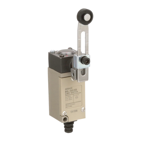
General-purpose Limit Switch
HL-5000
Economical, Miniature Limit Switch
Boasting Rigid Construction
■ The Head, Box, and Cover mate with ridged surfaces to maintain
strength.
■ A unique Head structure provides a large OT for smooth operation.
■ Easy-to-wire conduit opening design.
■ Ideal for application in printing machines, forming machines, and
light machines.
(High Switches with high sealing characteristics, such as WL or
D4C Switches, in locations subject to oil, water, or precipitation.)
■ Models with grounding terminals conform to the CE marking.
■ Approved by CCC (Chinese standard).
(Ask your OMRON representative for information on approved
models.)
Be sure to read Safety Precautions on page 4 to 5 and
Safety Precautions for All Limit Switches.
Model Number Structure
Model Number Legend
HL-5 @@
å`HL-5ņņ
(1)(2)
(1) Actuators
000: Roller lever
030: Adjustable roller lever
050: Adjustable rod lever
100: Sealed plunger
200: Sealed roller plunger
300: Coil spring
(2) Ground Terminal Specifications
Blank : Without ground terminal
G
: With ground terminal/M5 tapping on the rear side
Ordering Information
Actuator
Roller lever
Adjustable
roller lever
Adjustable
rod lever
Sealed
plunger
Sealed roller
plunger
Coil spring
* HL-5000 Limit Switches are offered with a choice of ground terminal/M5
tapping on the rear side conforming to various standards. When placing an
order, add the code to the model number to indicate if ground terminal/M5
tapping on the rear side is required.
-G: with ground terminal/M5 tapping on the rear side.
http://www.ia.omron.com/
Specifications
Approved Standards
Note: Ask your OMRON representative for information on approved models.
Ratings
voltage
125 VAC
250 VAC
12 VDC
24 VDC
125 VDC
250 VDC
Note: 1. The above figures are for steady-state currents.
Model
HL-5000
*
HL-5030
*
Inrush
current
HL-5050
*
Approved Standard Ratings
CCC (GB14048.5)
HL-5100
*
HL-5200
HL-5300
(c)Copyright OMRON Corporation 2007 All Rights Reserved.
Agency
Standard
CCC (CQC)
GB14048.5
Non-inductive load (A)
Rated
Resistive
Lamp load
load
NC
NO
NC
5
1.5
5
1
5
3
5
3
−
0.4
0.2
−
0.4
0.2
2. Inductive loads have a power factor of 0.4 min. (AC) and a time
constant of 7 ms max. (DC).
3. Lamp load has an inrush current of 10 times the steady-state current.
4. Motor load has an inrush current of 6 times the steady-state current.
NC
24 A max.
NO
12 A max.
Applicable category and ratings
AC-15 3 A/250 VAC
File No.
2003010303077624
Inductive load (A)
Inductive
Motor load
load
NO
NC
NO
NC
NO
0.7
3
2
1
0.5
3
1.5
0.8
4
3
4
3
−
−
−
−
1
Advertisement
Table of Contents

Related Manuals for Omron HL-5030


Summary of Contents for Omron HL-5030
- Page 1 Standard File No. (1)(2) CCC (CQC) GB14048.5 2003010303077624 (1) Actuators Note: Ask your OMRON representative for information on approved models. 000: Roller lever Ratings 030: Adjustable roller lever 050: Adjustable rod lever Non-inductive load (A) Inductive load (A) 100: Sealed plunger...
-
Page 2: Engineering Data
* The values are calculated at an operating temperature of +5 C to +35 C, and an operating humidity of 40% to 70%RH. Contact your OMRON sales representative for more detailed information on other operating environments. Structure and Nomenclature Structure... - Page 3 30±0.8 mm 40±0.8 mm * Measured with the types of the 31.5-mm arm or rod length. OF and RF measured at the arm length of 75 mm for HL-5030, and 145 mm for HL-5050 (reference values). HL-5030 HL-5050 3.09 N 1.60 N...
-
Page 4: Safety Precautions
Note: If the head direction has been changed, check the torque of each screw Cover mounting screw and make sure that the screws are free of foreign substances, and that each screw is tightened to the proper torque. Cover Rubber connector Terminal http://www.ia.omron.com/ (c)Copyright OMRON Corporation 2007 All Rights Reserved. -
Page 5: Mounting Holes
The tightening torque applied to each bolt is 4.90 to 5.88 N·m. To mount the Limit Switch more securely, use two M5 screw holes on the rainwater, seawater, or oily water. Consult your OMRON rear panel and rear holes for positioning if the model is the HL- representative for models resisting rainwater, seawater, and oily 5@@@G-Series Limit Switches. -
Page 6: Precautions For Safe Use
Limit Switch itself may become damaged or burnt. Precautions for Correct Use For details, refer to Precautions for Correct Use in the Technical Guide for Limit Switches. http://www.ia.omron.com/ (c)Copyright OMRON Corporation 2007 All Rights Reserved. - Page 7 • If the load is a minute voltage or current load, use a dedicated Switch for minute loads. The reliability of silver-plated contacts, which are used by standard Switches, will be insufficient if the load is a minute voltage or current load. http://www.ia.omron.com/ (c)Copyright OMRON Corporation 2007 All Rights Reserved.
- Page 8 = 0.5 × 10 –6 /operations indicates that the estimated malfunction rate is less than 1/2,000,000 operations with a reliability Unusable range level of 60%. 1 mA 100 mA 160 mA 1,000 Current (mA) http://www.ia.omron.com/ (c)Copyright OMRON Corporation 2007 All Rights Reserved.
-
Page 9: Operating Environment
Otherwise, sulfuric film will be generated on the contacts and contact failures may result. Use the Switch with gold- plated contacts or use a dedicated Switch for minute loads instead. http://www.ia.omron.com/ (c)Copyright OMRON Corporation 2007 All Rights Reserved. -
Page 10: Operation
(including the environment and operating frequency) to If the dog touches the lever as shown below, the operating position confirm that no problems will occur in actual. will not be stable. Incorrect Correct http://www.ia.omron.com/ (c)Copyright OMRON Corporation 2007 All Rights Reserved. - Page 11 • When using a pin-plunger actuator, make sure that the stroke of the actuator and the movement of the dog are located along a single straight line. Incorrect Correct Operating Operating body body http://www.ia.omron.com/ (c)Copyright OMRON Corporation 2007 All Rights Reserved.
- Page 12 0.5 to 0.7 (TT) Note: The above y values indicate the ratio ranges based on TT (total travel). Therefore, the optimum pressing distance of the dog is between 50% and 80% (or 50% and 70%). http://www.ia.omron.com/ (c)Copyright OMRON Corporation 2007 All Rights Reserved.
-
Page 13: Maintenance And Repairs
Therefore, reset may be delayed or reset may fail if the Switch is used with the actuator continually pressed in. Contact your OMRON representative if the Switch is to be used for this type of environment or application. -
Page 14: Warranty
Warranty and Limitations of Liability WARRANTY OMRON's exclusive warranty is that the products are free from defects in materials and workmanship for a period of one year (or other period if specifi ed) from date of sale by OMRON. OMRON MAKES NO WARRANTY OR REPRESENTATION, EXPRESS OR IMPLIED, REGARDING NON-INFRINGEMENT, MERCHANTABILITY, OR FITNESS FOR PARTICULAR PURPOSE OF THE PRODUCTS.