
Related Manuals for Eaton 93PM G2


Summary of Contents for Eaton 93PM G2
- Page 1 E E a a t t o o n n 9 9 3 3 P P M M G G 2 2 U U P P S S Eaton 93PM G2 UPS 50 – 360 kVA User’s and Installation Guide...
- Page 2 The contents of this manual are the copyright of the publisher and may not be reproduced (even extracts) without the written approval of Eaton Corporation. Every care has been taken to ensure the accuracy of the information contained in this manual, but no liability can be accepted for any errors or omission. The right to make design modifications is reserved.
- Page 3 Introduction to Eaton UPS........
- Page 4 Menu structure of the 93PM G2 UPS ........
- Page 5 APPENDIX B: Recommended security hardening guidelines ........105 EATON 93PM G2 UPS USER’S AND INSTALLATION GUIDE...
- Page 6 Index ............. 108 EATON 93PM G2 UPS USER’S AND INSTALLATION GUIDE...
- Page 7 These symbols indicate a hazardous situation or action. Symbols are used to warn of situations, which can cause environmental damage and personal injury. General warning sign Explosion and fire hazard Battery hazard EATON 93PM G2 UPS USER’S AND INSTALLATION GUIDE P-164000956 - February 2021 www.eaton.eu...
- Page 8 These symbols are used in warnings and notifications to indicate an action that must be taken. The mandatory action symbols are shown below. Wear eye protection General symbol for mandatory action EATON 93PM G2 UPS USER’S AND INSTALLATION GUIDE P-164000956 - February 2021 www.eaton.eu...
- Page 9 1 1 . . 4 4 G G l l o o s s s s a a r r y y The following acronyms are used in Eaton documentation to refer to Eaton UPS products or their parts. Table 1. Glossary of acronyms...
- Page 10 Maintenance Bypass Switch Maintenance Isolation Switch Module Output Breaker Silicon-Controlled Rectifier Uninterruptible Power Module Uninterruptible Power Supply VRLA Valve Regulated Lead Acid (battery) 1 1 0 0 EATON 93PM G2 UPS USER’S AND INSTALLATION GUIDE P-164000956 - February 2021 www.eaton.eu...
- Page 11 93pm. DANGER Operations inside the UPS must be done by an authorized Eaton Customer Service Engineer or by other qualified service personnel authorized by Eaton. There are no user-serviceable parts inside the UPS. The UPS operates with mains, battery or bypass power. It contains components that carry high currents and voltage.
- Page 12 Keep the surroundings of the UPS uncluttered, clean, and free from excess moisture. Obey all DANGER, CAUTION, and WARNING notices affixed to the equipment. 1 1 2 2 EATON 93PM G2 UPS USER’S AND INSTALLATION GUIDE P-164000956 - February 2021 www.eaton.eu...
- Page 13 RoHS Directive 2011/65/EU Declarations of conformity with UPS harmonized standards and directives EN 62040-1 (Safety), EN 62040-2 (EMC) and EN 63000 (RoHS) are available at www.eaton.eu or by contacting your nearest Eaton office or authorized partner. 2 2 . . 4 4...
- Page 14 Indicates that a risk of electric shock is present and the associated warning should be observed. CAUTION: REFER TO OPERATOR'S MANUAL Refer to your operator's manual for additional information, such as important operating and maintenance instructions. 1 1 4 4 EATON 93PM G2 UPS USER’S AND INSTALLATION GUIDE P-164000956 - February 2021 www.eaton.eu...
- Page 15 • a question about any of the information in this manual • a question that this manual does not answer 1 1 5 5 EATON 93PM G2 UPS USER’S AND INSTALLATION GUIDE P-164000956 - February 2021 www.eaton.eu...
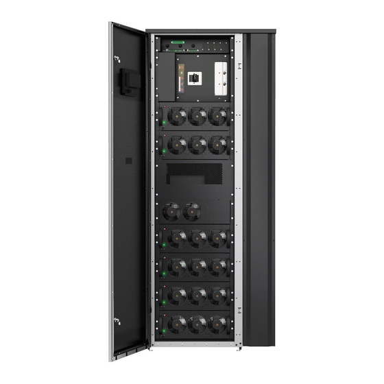
- Page 16 Each UPS cabinet has a centralized system static bypass. Eaton 93PM G2 output power ratings are based on 50 kVA and 60 kVA rated uninterruptible power modules (UPMs) installed in 200/240 kVA or 300/360 kVA UPS frames. A single UPS cabinet can house from one to four or six UPMs.
- Page 17 Startup and operational checks must be done by an authorized Eaton Customer Service Engineer NOTE: or by other qualified service personnel authorized by Eaton, or the terms specified in the Warranty (see General information about warranty) become void. This service is offered as part of the sales contract 10.1...
- Page 18 10. Static switch module (SSM) Figure 4. Main parts with MBS, inside 1. UPM 1 2. UPM 2 3. UPM 3 4. UPM 4 1 1 8 8 EATON 93PM G2 UPS USER’S AND INSTALLATION GUIDE P-164000956 - February 2021 www.eaton.eu...
- Page 19 AC power, identically to double conversion mode. In the VMMS mode, the 93PM G2 UPS system is able to optimize the load level per power module: the operating efficiency is significantly improved when operating load is below 50 % of UPS capacity.
- Page 20 Static switch Bypass input Main power flow Rectifier Rectifier input Energized Inverter Output De-energized DC/DC Battery breaker Trickle current converter Battery Closed Open 2 2 0 0 EATON 93PM G2 UPS USER’S AND INSTALLATION GUIDE P-164000956 - February 2021 www.eaton.eu...
- Page 21 The only step needed to come out of ready state is to gate the IGBT switches. Since DC voltage is constantly present, the inverter is able to start instantaneously: the 2 ms activation is practically seamless. 2 2 1 1 EATON 93PM G2 UPS USER’S AND INSTALLATION GUIDE P-164000956 - February 2021 www.eaton.eu...
- Page 22 The energy saver system increases system efficiency up to 99 % when supplying 20- 100% of nominal load, reducing energy losses by up to 80%. 2 2 2 2 EATON 93PM G2 UPS USER’S AND INSTALLATION GUIDE P-164000956 - February 2021...
- Page 23 If the input power fails to return or is not within the acceptance windows required for normal operation, the DC/DC converter continues discharging the stored energy source until the end-of-discharge battery 2 2 3 3 EATON 93PM G2 UPS USER’S AND INSTALLATION GUIDE P-164000956 - February 2021...
- Page 24 Figure 8. Path of current through the UPS in the bypass mode Static switch Bypass input Main power flow Rectifier Rectifier input Energized Inverter Output De-energized 2 2 4 4 EATON 93PM G2 UPS USER’S AND INSTALLATION GUIDE P-164000956 - February 2021 www.eaton.eu...
- Page 25 P P o o w w e e r r w w a a r r e e H H o o t t S S y y n n c c The Eaton Powerware Hot Sync technology is an algorithm that eliminates the single point of failure in a parallel system and therefore enhances system reliability.
- Page 26 S S y y n n c c C C o o n n t t r r o o l l The Eaton Sync Control maintains the critical load outputs of two separate single UPS systems in synchronization. Use of the Eaton Fixed Master Sync Control provides uninterrupted transfer of the load from one load bus to another by means of downstream, dual-source, solid-state transfer switches.
- Page 27 S S i i n n g g l l e e f f e e e e d d k k i i t t The Eaton 93PM G2 UPS is configured for dual feed by standard, requiring a separate feed for rectifier and static bypass input.
- Page 28 If you need to connect other type of batteries or other energy storage means, consult a certified service technician before you proceed with the installation. Eaton offers external battery cabinets to be used together with the Eaton 93PM G2 UPS. 3 3 . . 8 8 . . 1 1...
- Page 29 Internal maintenance bypass switch (MBS) — Battery breaker for external batteries Sync control interface Top air exhaust kit Parallel cable kit Single feed kit 2 2 9 9 EATON 93PM G2 UPS USER’S AND INSTALLATION GUIDE P-164000956 - February 2021 www.eaton.eu...
- Page 30 — = Not available Additional options and accessories are also available. These include different software and connectivity options and external switchgear and power distribution options. 3 3 0 0 EATON 93PM G2 UPS USER’S AND INSTALLATION GUIDE P-164000956 - February 2021 www.eaton.eu...
- Page 31 Startup and operational checks must be performed by an authorized Eaton Customer Service NOTE: Engineer or by other qualified service personnel authorized by Eaton, or the terms specified in the Warranty (see Section General information about warranty) become void. This service is offered as a 10.1...
- Page 32 (based on ANSI/ISA S-71.04 classifications). If the UPS is used in a more aggressive environment, it can cause reduced product life and possibly early failure. If the installation location does not meet the recommended environment, contact Eaton service representative for further information.
- Page 33 Table 4. UPS cabinet maximum weights UPS model Shipping weight [kg] Installed weight [kg] Floor loading [kg/m 93PM G2 50(200) 93PM G2 100(200) 3 3 3 3 EATON 93PM G2 UPS USER’S AND INSTALLATION GUIDE P-164000956 - February 2021 www.eaton.eu...
- Page 34 Shipping dimensions 1000 x 1200 x 2168 Cabinet dimensions 800 x 990 x 1987 Figure 10. 93PM G2 UPS top dimensions, with top-air exhaust option 3 3 4 4 EATON 93PM G2 UPS USER’S AND INSTALLATION GUIDE P-164000956 - February 2021...
- Page 35 Figure 11. 93PM G2 UPS top dimensions, with top-air exhaust option The UPS cabinets use forced air cooling to regulate internal component temperature. By standard, air inlets are in the front of the cabinet and outlets are in the back. You must allow clearance in front of and behind each cabinet for proper air circulation.
- Page 36 The cooling air entering the UPS must not exceed +40 °C. Avoid high ambient temperature, moisture, and humidity. For ventilation requirements, see 93PM G2 heat rejection in the following table. Table 7. Air conditioning or ventilation requirements during full load operation...
- Page 37 Rectifier, bypass and maintenance bypass input Phase cables [mm fuse [A] PE cable [mm 93PM G2 xxx(200) 93PM G2 xxx(240) 0.9 93PM G2 xxx(300) 2 x 185 93PM G2 xxx(360) 0.9 2 x 185 UPS CTO models Rectifier, bypass and...
- Page 38 UPS CTO models Rectifier, bypass and maintenance bypass input Phase cables [mm fuse [A] PE cable [mm 93PM G2 xxx(180) 0.9 93PM G2 xxx(250) 2 x 120 93PM G2 xxx(300) 0.9 2 x 185 CAUTION Make sure that prospective short-circuit current resulting at the input terminals of the UPS is equal or less than conditional short-circuit current declared on the type plate (and technical specification) of the UPS.
- Page 39 UPS CTO models Battery cable, pos. & neg. line [mm Battery PE cable Battery fuse [A] 93PM G2 xxx(180) 0.9 2 x 95 per pole 93PM G2 xxx(250) 2 x 120 per pole 93PM G2 xxx(300) 0.9 2 x 150 per pole UPS power upgrading is possible only if the sizing of the external cables is sufficient.
- Page 40 UPS output / bypass Rated voltage [V] Rated current [A] Maximum current [A] Rated current [A] 93PM G2 xxx(300) 93PM G2 xxx(360) 0.9 UPS CTO models Rectifier input UPS output / bypass Rated voltage [V] Rated current [A] Maximum current [A]...
- Page 41 Rated current [A] Maximum current* [A] 93PM G2 xxx(200) 93PM G2 xxx(240) 0.9 pF 93PM G2 xxx(200) 93PM G2 xxx(360) 0.9 pF *) Maximum battery current calculated at rated load in the end of discharge of VRLA battery (1.67 V per cell).
- Page 42 Source protection for the AC input to bypass must suit the characteristics of the load and take into account effects such as inrush or starting current. 4 4 2 2 EATON 93PM G2 UPS USER’S AND INSTALLATION GUIDE P-164000956 - February 2021...
- Page 43 2. Make a visual inspection and make sure that there are no signs of shipping damages. Examine the indicators. See the DropNTell inside the package. 4 4 3 3 EATON 93PM G2 UPS USER’S AND INSTALLATION GUIDE P-164000956 - February 2021...
- Page 44 4. Fasten the ramp to the pallet. 5. Turn the leveling feet counterclockwise completely up to lift them off of the pallet. 6. Open the door of the cabinet. 4 4 4 4 EATON 93PM G2 UPS USER’S AND INSTALLATION GUIDE P-164000956 - February 2021 www.eaton.eu...
- Page 45 It is recommended to attach the lower cover plates to the ends of the cabinet (included in the package). 4 4 5 5 EATON 93PM G2 UPS USER’S AND INSTALLATION GUIDE P-164000956 - February 2021 www.eaton.eu...
- Page 46 UPS must be made by a locally qualified electrician. The electrical installation procedure is described in the following section. The installation inspection and the initial start-up of the UPS and installing an extra battery cabinet must be carried out by an authorized Eaton Customer Service Engineer or by other qualified service personnel authorized by Eaton.
- Page 47 4. Top cable access gland plate 2. Bottom cable access gland plate 5. Rear cable access gland plate 3. Communication cable access gland plates 4 4 7 7 EATON 93PM G2 UPS USER’S AND INSTALLATION GUIDE P-164000956 - February 2021 www.eaton.eu...
- Page 48 Figure 15. Cable support beams Figure 16. Connector locations X4 Battery X2 Bypass output Batt + X2:L1 Batt - X2:L2 X2:L3 4 4 8 8 EATON 93PM G2 UPS USER’S AND INSTALLATION GUIDE P-164000956 - February 2021 www.eaton.eu...
- Page 49 X11: Sync control interface (optional) Bypass L1 SYNC L1 Bypass L2 SYNC L2 Bypass L3 SYNC L3 Output L1 Unused Output L2 Unused Output L3 Unused 4 4 9 9 EATON 93PM G2 UPS USER’S AND INSTALLATION GUIDE P-164000956 - February 2021 www.eaton.eu...
- Page 50 The external battery breakers can be tripped (switched off) by energizing its shunt trip coil. The shunt trip coils are energized (controlled) through connector X8. The status signal of the external battery breaker is also connected to connector X8. Status contacts of the Eaton battery breakers are open if the breaker itself is open.
- Page 51 I I n n s s t t a a l l l l i i n n g g U U P P S S e e x x t t e e r r n n a a l l b b a a t t t t e e r r y y c c a a b b i i n n e e t t a a n n d d b b a a t t t t e e r r y y p p o o w w e e r r c c a a b b l l i i n n g g There is a vast offering of different Eaton external battery cabinets available for the 93PM G2 UPSs.
- Page 52 NO and NC connections of the EPO switch. EPO connector (front view): • A = Normally open • B = Normally closed 5 5 2 2 EATON 93PM G2 UPS USER’S AND INSTALLATION GUIDE P-164000956 - February 2021 www.eaton.eu...
- Page 53 I I n n s s t t a a l l l l i i n n t t e e r r f f a a c c e e c c o o n n n n e e c c t t i i o o n n s s The 93PM G2 UPS contains a total of five (5) customer input connectors, which can be used for giving remote control commands to the UPS.
- Page 54 Additional relay outputs are available with mini-slot cards. Relay outputs can be configured to be activated by various events. Configuration can be done by an authorized Eaton Customer Service Engineer or by other qualified service personnel authorized by Eaton.
- Page 55 W W i i r r i i n n g g p p a a r r a a l l l l e e l l 9 9 3 3 P P M M G G 2 2 U U P P S S s s y y s s t t e e m m s s The outputs of multiple 93PM G2 UPS systems can be connected in parallel. Up to eight units can be paralleled.
- Page 56 P P a a r r a a l l l l e e l l s s y y s s t t e e m m c c a a b b l l i i n n g g Figure 22. Principle of paralleled UPS systems 5 5 6 6 EATON 93PM G2 UPS USER’S AND INSTALLATION GUIDE P-164000956 - February 2021...
- Page 57 A 12-pin terminal block for external parallel control signals is accessible on the right side of the communication interface, on the top section of the UPS (see Figure X9 External parallel interface). 5 5 7 7 EATON 93PM G2 UPS USER’S AND INSTALLATION GUIDE P-164000956 - February 2021 www.eaton.eu...
- Page 58 This drawing is for distributed bypass wiring purposes and it is not a floor layout plan. UPSs can be NOTE: placed in any physical order. 5 5 8 8 EATON 93PM G2 UPS USER’S AND INSTALLATION GUIDE P-164000956 - February 2021 www.eaton.eu...
- Page 59 Use twisted pair wiring between the UPS and MOB AUX contacts. Always confirm contact operation prior to wiring. 5 5 9 9 EATON 93PM G2 UPS USER’S AND INSTALLATION GUIDE P-164000956 - February 2021 www.eaton.eu...
- Page 60 The UPS Battery Aux and 24 Vdc Shunt Trip signal wiring from the UPS must be connected to the DC source disconnect device. Also 48 Vdc Shunt Trip signal can be utilized. See Figure Battery trip wiring for 93PM G2 UPS. • Battery Aux and Shunt Trip wiring should be a minimum of 1.5 mm •...
- Page 61 M M i i n n i i S S l l o o t t c c a a r r d d s s The Eaton 93PM G2 UPS has four MiniSlot communication bays. For instructions on how to install a MiniSlot card, refer to Section MiniSlot interface connections.
- Page 62 UPS information (meters and status) to a Building Management System (BMS) using the Modbus RTU and TCP protocols as well as BACnet protocols. Figure 31. PX Gateway Card 6 6 2 2 EATON 93PM G2 UPS USER’S AND INSTALLATION GUIDE P-164000956 - February 2021 www.eaton.eu...
- Page 63 Protector can be remotely supervised and managed by the Intelligent Power Manager (IPM) application. Intelligent Power Software suite is delivered on a CD with the UPS. Alternatively, you can download it from the Eaton web page. Some of the advanced features of IPM require a license, contact your Eaton representative for details.
- Page 64 C C o o n n f f i i g g u u r r i i n n g g r r e e l l a a y y s s The 93PM G2 offers one native relay output. Additionally, each of the four MiniSlots can be equipped with a 5–relay adapter for additional relay outputs.
- Page 65 2. In the sign in window, click the password field containing the 4 dots. Figure 34. Sign in window with the password field 3. Enter the password 0101 and press 4. Select Continue. 6 6 5 5 EATON 93PM G2 UPS USER’S AND INSTALLATION GUIDE P-164000956 - February 2021 www.eaton.eu...
- Page 66 Figure 36. Options for relay outputs configuration 7. Enter the code(s) of the function(s) that you want to trigger the relay when they become active. 6 6 6 6 EATON 93PM G2 UPS USER’S AND INSTALLATION GUIDE P-164000956 - February 2021...
- Page 67 1. Cable exit opening for up to 12 mm 3. K1 thru K5 terminal connections (½”) conduit for relay contacts to operator's monitoring equipment 2. Signal input connector with voltage supply 6 6 7 7 EATON 93PM G2 UPS USER’S AND INSTALLATION GUIDE P-164000956 - February 2021 www.eaton.eu...
- Page 68 Settings→Information. If the UPS need to be operated with another voltage or frequency, contact your closest Eaton office or Eaton authorized partner. The UPS is not a measuring device. All the displayed measurements are approximate values only.
- Page 69 UPS. The most urgent condition is always the one shown. Only one color is shown at a time. The table below defines which color is shown. 6 6 9 9 EATON 93PM G2 UPS USER’S AND INSTALLATION GUIDE P-164000956 - February 2021...
- Page 70 Only one color is shown at a time. The table below defines the color coding. Table 19. Color LED indicators Color LED indicators (UPM) UPM status UPM starts up UPM in online, battery or EnergyAware mode 7 7 0 0 EATON 93PM G2 UPS USER’S AND INSTALLATION GUIDE P-164000956 - February 2021 www.eaton.eu...
- Page 71 M M e e n n u u s s t t r r u u c c t t u u r r e e o o f f t t h h e e 9 9 3 3 P P M M G G 2 2 U U P P S S The following table shows the menu structure of the 93PM G2 UPS.
- Page 72 Active events log can be opened by tapping the error indicator. UPS module map Module map shows the status of each UPM. 7 7 2 2 EATON 93PM G2 UPS USER’S AND INSTALLATION GUIDE P-164000956 - February 2021 www.eaton.eu...
- Page 73 Automatically updated information about UPS output kVA rating and the amount of redundant UPMs. About Version information. Contact Eaton Phone numbers to Eaton service locations worldwide. UPS CTO and serial numbers. You need to sign in to modify the Configuration settings. Table 22. Configuration settings Setting...
- Page 74 30 minutes before trying again. Table 23. Default passwords Level Name Password Description USER NONE USER CONTROL 1111 USER + CONTROL 7 7 4 4 EATON 93PM G2 UPS USER’S AND INSTALLATION GUIDE P-164000956 - February 2021 www.eaton.eu...
- Page 75 UPSs and UPMs in the system. The system status is shown as UNIT ONLINE. The UPM status is shown as ACTIVE. 7 7 5 5 EATON 93PM G2 UPS USER’S AND INSTALLATION GUIDE P-164000956 - February 2021...
- Page 76 The UPS system transfers to the bypass mode and the critical load is immediately supplied by the bypass source. If the bypass source is not available, the power processor remains on and an alarm sounds. 7 7 6 6 EATON 93PM G2 UPS USER’S AND INSTALLATION GUIDE P-164000956 - February 2021 www.eaton.eu...
- Page 77 Note that the Variable Module Management System mode commands are displayed only if enabled NOTE: at the factory or by an Eaton authorized Customer Service Engineer. To transfer the critical load to the double conversion mode. 1. In the home screen, press Controls.
- Page 78 Note that the Variable Module Management System mode commands are displayed only if enabled NOTE: at the factory or by an Eaton authorized Customer Service Engineer. To transfer the critical load to the double conversion mode. 1. In the home screen, press Controls.
- Page 79 The system controls screen is displayed. 2. In the System controls screen, press UPS controls. 3. In the UPS control screen, select Shut down UPS. 7 7 9 9 EATON 93PM G2 UPS USER’S AND INSTALLATION GUIDE P-164000956 - February 2021 www.eaton.eu...
- Page 80 The Select module screen is displayed. 3. Select the UPM you want to shut down. 4. In the UPM control screen, select Shut down module. 8 8 0 0 EATON 93PM G2 UPS USER’S AND INSTALLATION GUIDE P-164000956 - February 2021 www.eaton.eu...
- Page 81 When the EPO switch is activated, all power to the critical load is lost. Use this feature only in case of emergency. The following instructions are for the EPO switch supplied by Eaton Corporation. If you are using a NOTE: customer-supplied EPO switch, it may not activate in the same way.
- Page 82 7. Open the incoming feeder to disconnect the power from rectifier input terminals X1. 8. Open all battery breakers feeding the UPS battery input terminals X4. The UPS is now in the maintenance bypass mode: 8 8 2 2 EATON 93PM G2 UPS USER’S AND INSTALLATION GUIDE P-164000956 - February 2021 www.eaton.eu...
- Page 83 To turn the UPS back to the double conversion mode: 8 8 3 3 EATON 93PM G2 UPS USER’S AND INSTALLATION GUIDE P-164000956 - February 2021...
- Page 84 Select UPS controls (Single UPS) or System controls (UPS system). c. Press Go online button. Confirm your selection. The UPS is now in the double conversion mode. 8 8 4 4 EATON 93PM G2 UPS USER’S AND INSTALLATION GUIDE P-164000956 - February 2021 www.eaton.eu...
- Page 85 Figure 43. Normal positions of the switches Bypass input Bypass input switch (BIS) S1 Rectifier input Maintenance bypass switch (MBS) S2 UPS output 8 8 5 5 EATON 93PM G2 UPS USER’S AND INSTALLATION GUIDE P-164000956 - February 2021 www.eaton.eu...
- Page 86 UPS system. WARNING All service and maintenance work must be done only by service personnel qualified and authorized by Eaton. CAUTION A warning label, shown in Figure Warning label, must be installed at the UPS...
- Page 87 The majority of the service and maintenance work must be performed by service personnel qualified by Eaton. Only the actions described in Section and Section Monthly maintenance are allowed to be 8.3.2...
- Page 88 4. Make sure that the UPS is in the normal mode (the normal mode status indicator is illuminated). If an alarm lamp is lit or the normal mode status indicator is not lit, contact an Eaton service representative. 8 8 . . 3 3 . . 2 2 M M o o n n t t h h l l y y m m a a i i n n t t e e n n a a n n c c e e Do this once a month.
- Page 89 M M a a i i n n t t e e n n a a n n c c e e t t r r a a i i n n i i n n g g For more information about training and other services, contact your Eaton representative.
- Page 90 A A b b o o u u t t t t e e c c h h n n i i c c a a l l d d a a t t a a For a complete technical specification, contact your Eaton representative. Due to continuous product improvement programs, specifications are subject to change without notice.
- Page 91 * ) For maximum lifetime for UPS and batteries, keep the environment in the recommended range. ** ) Limit based on ASHRAE 90.1-2013. Rapidly increasing temperature may cause condensation on colder surfaces. For more technical details please refer to the technical specification of the 93PM G2. 9 9 1 1 EATON 93PM G2 UPS USER’S AND INSTALLATION GUIDE...
- Page 92 Eaton Field Service Engineer or by other qualified service personnel authorized by Eaton. Service and maintenance of the UPS shall also be performed only by an authorized Eaton Field Service Engineer or by other qualified service personnel authorized by Eaton. Otherwise the warranty will be voided.
- Page 93 APPENDIX A: Relay alarms These alarm codes are for 91PS/93PS/93PM/93PM G2 Modular UPS, 8-500 kVA. Name 24V Power Supply Failed 5V Power Supply Failed ABM Active ABM Enable ABM Installed ABM State Reset ABM State Charging ABM State Floating ABM State Resting...
- Page 94 Bypass Breaker Active Bypass Breaker Installed Bypass Command Bypass Hot Bypass Installed Bypass Not Available Bypass Over Temperature Bypass Over Temperature Trip Bypass Phase Rotation 9 9 4 4 EATON 93PM G2 UPS USER’S AND INSTALLATION P-164000956 - February 2021 www.eaton.eu GUIDE...
- Page 95 Clock Set Done Command Received Configuration Error CSB Control Power CSB EEPROM Version Downgrade CSB Software Incompatible DC Link Over Voltage DC Link Under Voltage 9 9 5 5 EATON 93PM G2 UPS USER’S AND INSTALLATION P-164000956 - February 2021 www.eaton.eu GUIDE...
- Page 96 External CAN Abnormal or Configuration Mismatch External Communications failure Fan Failed Fan Power Board Cool Fan Failed Frequency Auto Detected Fuse Failed Ground Wiring Fault 9 9 6 6 EATON 93PM G2 UPS USER’S AND INSTALLATION P-164000956 - February 2021 www.eaton.eu GUIDE...
- Page 97 Inverter Over Temperature Trip Inverter Overload Trip Inverter Startup Failure Inverter Switchgear Closed Inverter Switchgear Failed Load Off Command Load Off Command Load Power Off 9 9 7 7 EATON 93PM G2 UPS USER’S AND INSTALLATION P-164000956 - February 2021 www.eaton.eu GUIDE...
- Page 98 On MBS, Battery On MBS, ESS Active On MBS, HRS Active On MBS, On Bypass On MBS, Starting On MBS, Shutdown On MBS, Unit Online 9 9 8 8 EATON 93PM G2 UPS USER’S AND INSTALLATION P-164000956 - February 2021 www.eaton.eu GUIDE...
- Page 99 PhaseA Overload Level2 PhaseA Overload Level3 PhaseA Overload Level4 PhaseB Overload Level2 PhaseB Overload Level3 PhaseB Overload Level4 PhaseC Overload Level2 PhaseC Overload Level3 9 9 9 9 EATON 93PM G2 UPS USER’S AND INSTALLATION P-164000956 - February 2021 www.eaton.eu GUIDE...
- Page 100 Service Required Shutdown Command Shutdown Imminent Signal Input 1 On Signal Input 2 On Signal Input 3 On Signal Input 4 On 1 1 0 0 0 0 EATON 93PM G2 UPS USER’S AND INSTALLATION P-164000956 - February 2021 www.eaton.eu GUIDE...
- Page 101 Signal Input Remote VMMS Command Signal Input Remote VMMS/ESS Off Signal Input Reset Alarms Signal Input Transformer Over Temperature Signal Input Single UPS System 1 1 0 0 1 1 EATON 93PM G2 UPS USER’S AND INSTALLATION P-164000956 - February 2021 www.eaton.eu GUIDE...
- Page 102 Too Many Inverter Transfers Too Many Battery Transfers Transformer Fan Failed Transformer Over Temperature Trip Turn Off Battery Command Turn to Battery Command UPM_NB_FAN_SPEED_ERROR 1 1 0 0 2 2 EATON 93PM G2 UPS USER’S AND INSTALLATION P-164000956 - February 2021 www.eaton.eu GUIDE...
- Page 103 UPM Unlock UPMs Not Redundant UPS Exit ECT Process UPS Normal Command UPS Not Redundant UPS On Battery UPS On Bypass 1 1 0 0 3 3 EATON 93PM G2 UPS USER’S AND INSTALLATION P-164000956 - February 2021 www.eaton.eu GUIDE...
- Page 104 UPS System Off UPS System Online Utility Not Available Warranty Out of Date VMMS Not Available VMMS Active VMMS Enable VMMS Installed 1 1 0 0 4 4 EATON 93PM G2 UPS USER’S AND INSTALLATION P-164000956 - February 2021 www.eaton.eu GUIDE...
- Page 105 And, such users are 1 1 0 0 5 5 EATON 93PM G2 UPS USER’S AND INSTALLATION P-164000956 - February 2021 www.eaton.eu...
- Page 106 Level 1: Control password for User • Level 2: Configure password for User • Level 3: Service password for an authorized Eaton Customer • Service Engineer or qualified service personnel authorized by Eaton Users are recommended to change default passwords on first use of the system.
- Page 107 4. National Institute of Technology (NIST) Interagency “Guidelines on Firewalls and Firewall Policy, NIST Special Publication 800-41”, October 2009. http://nvlpubs.nist.gov/nistpubs/Legacy/SP/ nistspecialpublication800-41r1.pdf 1 1 0 0 7 7 EATON 93PM G2 UPS USER’S AND INSTALLATION P-164000956 - February 2021 www.eaton.eu GUIDE...
- Page 108 Shut down the UPS system and critical load ..78 Start the UPS system in the double conversion mode ............75 Transfer from the bypass mode to the double Menu structure of the 93PM G2 UPS conversion mode ........76 User settings ..........73 Transfer from the double conversion mode to the bypass mode ........76...
- Page 109 Shut down a single UPS.......79 External parallel system control wiring...57 UPS controls and indicators Power wiring overview .........55 Control panel ..........68 Menu structure of the 93PM G2 UPS ....71 System events ..........71 UPS features Advanced Battery Management....25 Frequency Converter ........26 Power Conditioner ........26...
- Page 110 Eaton Power Quality Oy Koskelontie 13 FI-02920 Espoo, Finland www.eaton.eu Copyright © 2021 Eaton Corporation plc. All rights reserved. Unauthorized copying and lending are prohibited.