Endress+Hauser Micropilot FMR56 Operating Instructions Manual
Level radar
Hide thumbs
Also See for Micropilot FMR56:
- Operating instructions manual (198 pages) ,
- Technical information (103 pages) ,
- Brief operating instructions (72 pages)

Related Manuals for Endress+Hauser Micropilot FMR56


Summary of Contents for Endress+Hauser Micropilot FMR56
- Page 1 Products Solutions Services BA01127F/00/EN/01.13 71217606 Valid as of version 01.00.zz Operating Instructions Micropilot FMR56, FMR57 Level radar Level measurement in bulk solids...
-
Page 3: Table Of Contents
Micropilot FMR56, FMR57 Table of contents Table of contents Important document information ..4 Commissioning ....62 Document function ..... -
Page 4: Important Document Information
Important document information Micropilot FMR56, FMR57 Important document information Document function These Operating Instructions contain all the information that is required in various phases of the life cycle of the device: from product identification, incoming acceptance and storage, to mounting, connection, operation and commissioning through to troubleshooting, maintenance and disposal. - Page 5 Micropilot FMR56, FMR57 Important document information 1.2.3 Tool symbols Symbol Meaning Torx screwdriver A0013442 Flat blade screwdriver A0011220 Cross-head screwdriver A0011219 Allen key A0011221 Hexagon wrench A0011222 1.2.4 Symbols for certain types of information Symbol Meaning Allowed Indicates procedures, processes or actions that are allowed.
-
Page 6: Additional Documentation
The document types listed are available: • On the CD supplied with the device • In the Download Area of the Endress+Hauser Internet site: www.endress.com → Download 1.3.1 Safety Instructions (XA) Depending on the approval, the following Safety Instructions (XA) are supplied with the device. - Page 7 Micropilot FMR56, FMR57 Important document information Feature 010 Approval Available for Safety Instructions HART Safety Instructions PROFIBUS FOUNDATION Fieldbus ATEX: II 1/2 D Ex ta IIIC Txx°C Da/Db • FMR56 XA00682F XA00690F • FMR57 ATEX: II 3 G Ex nA IIC T6-T1 Gc •...
- Page 8 Important document information Micropilot FMR56, FMR57 Feature 010 ("Approval") Feature 030 ("Display, Operation") Ex marking L oder M IECEx ta [ia Db] IIIC Txx°C Da/Db L oder M IECEx Ex nA [ia Ga] IIC T6 Gc L oder M IECEx Ex ic [ia Ga] IIC T6 Gc...
-
Page 9: Basic Safety Instructions
The manufacturer is not liable for damage caused by improper or non-designated use. Verification for borderline cases: ‣ For special measured materials and cleaning agents, Endress+Hauser is glad to provide assistance in verifying the corrosion resistance of wetted materials, but does not accept any warranty or liability. -
Page 10: Workplace Safety
It meets general safety standards and legal requirements. It also complies with the EC directives listed in the device-specific EC Declaration of Conformity. Endress+Hauser confirms this by affixing the CE mark to the device. -
Page 11: Product Description
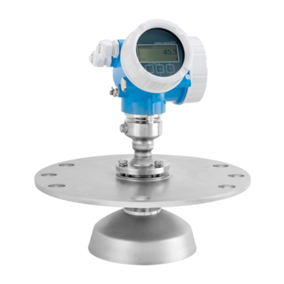
Micropilot FMR56, FMR57 Product description Product description Product design 3.1.1 Micropilot FMR56 A0016791 1 Design of the Micropilot FMR56 (26 GHz) Electronics housing Horn 80mm/100 mm (3in/4in), PP cladded Flange Mounting bracket 3.1.2 Micropilot FMR57 A0016807 2 Design of the Micropilot FMR57 (26 GHz) -
Page 12: Registered Trademarks
Product description Micropilot FMR56, FMR57 3.1.3 Electronics housing A0012422 3 Design of the electronics housing Electronics compartment cover Display module Main electronics module Cable glands (1 or 2, depending on instrument version) Nameplate I/O electronics module Terminals (pluggable spring terminals) -
Page 13: Incoming Acceptance And Product
Micropilot FMR56, FMR57 Incoming acceptance and product identification Incoming acceptance and product identification Incoming acceptance DELIVERY NOTE 1 = 2 A0013696 A0016870 Is the order code on the delivery note (1) identical to the order code on the product sticker (2)? - Page 14 Incoming acceptance and product identification Micropilot FMR56, FMR57 A0013696 A0014037 Are the CD-ROMs (product documentation, operating tool) and documentation present? If required (see nameplate): Are the Safety Instructions (XA) present? If one of the conditions does not comply, contact your Endress+Hauser distributor. Endress+Hauser...
-
Page 15: Product Identification
Micropilot FMR56, FMR57 Incoming acceptance and product identification Product identification The following options are available for identification of the measuring device: • Nameplate specifications • Extended order code with breakdown of the device features on the delivery note • Enter serial numbers from nameplates in W@M Device Viewer www.endress.com/deviceviewer... - Page 16 Incoming acceptance and product identification Micropilot FMR56, FMR57 Only 33 digits of the extended order code can be indicated on the nameplate. If the extended order code exceeds 33 digits, the rest will not be shown. However, the complete extended order code can be viewed in the operating menu of the device (Diagnostics →...
-
Page 17: Storage, Transport
Micropilot FMR56, FMR57 Storage, Transport Storage, Transport Storage conditions • Permitted storage temperature: –40 to +80 °C (–40 to +176 °F) • Use the original packaging. Transport product to the measuring point NOTICE Housing or antenna horn may be damaged or break away. -
Page 18: Installation
Installation Micropilot FMR56, FMR57 Installation Installation conditions 6.1.1 Mounting position • Recommended distance A from wall to outer edge of nozzle: ~ 1/6 of vessel diameter. Nevertheless the device should not be installed closer than 20 cm (7.87 in) to the vessel wall. - Page 19 Micropilot FMR56, FMR57 Installation 6.1.2 Vessel installations Avoid any installations (limit switches, temperature sensors, braces etc.) inside the signal beam. Take into account the beam angle (→ 23): A0018946 Endress+Hauser...
- Page 20 If the outer wall of the vessel is made of a non-conductive material (e.g. GRP), microwaves can also be reflected off interfering installations outside the signal beam (e.g. metallic pipes (1), ladders (2), grates (3), ...). Therefore, there should be no such interfering installations in the signal beam. Please contact Endress+Hauser for further information. Endress+Hauser...
- Page 21 Micropilot FMR56, FMR57 Installation A0017125 Endress+Hauser...
- Page 22 Installation Micropilot FMR56, FMR57 6.1.5 Optimization options • Antenna size The bigger the antenna, the smaller the beam angle α and the fewer interference echoes (→ 23). • Mapping The measurement can be optimized by means of electronic suppression of interference echoes.
- Page 23 Micropilot FMR56, FMR57 Installation 6.1.6 Beam angle A0016891 5 Relationship between beam angle α, distance D and beamwidth diameter W The beam angle is defined as the angle α where the energy density of the radar waves reaches half the value of the maximum energy density (3-dB-width). Microwaves are also emitted outside the signal beam and can be reflected off interfering installations.
- Page 24 Installation Micropilot FMR56, FMR57 FMR57 - Parabolic antenna Antenna size 200 mm (8 in) 250 mm (10 in) Beam angle α 4° 3,5° Measuring distance (D) Beamwidth diameter W 5 m (16 ft) 0.35 m (1.1 ft) 0.30 m (1 ft) 10 m (33 ft) 0.70 m (2.3 ft)
-
Page 25: Measuring Conditions
A [mm (in)] C [mm (in)] FMR56 400(15.7) 50 to 150(1.97 to 5.91) FMR57 Dielectric constants of important media commonly used in the industry are summarized in the document SD106F, which can be downloaded from the Endress+Hauser web page (www.endress.com). Endress+Hauser... -
Page 26: Installation In Vessel (Free Space)
Installation Micropilot FMR56, FMR57 Installation in vessel (free space) 6.3.1 Horn antenna with slip-on flange (FMR56) Alignment When using the Micropilot with a slip-on flange in explosion-hazardous areas, strictly observe all specifications in the relevant Safety Instructions (XA). • Align the antenna vertically to the product surface. - Page 27 Micropilot FMR56, FMR57 Installation 6.3.2 Horn antenna with mounting bracket (FMR56) A0016865 7 Installation of the horn antenna with mounting bracket (FMR50/FMR56) Align the antenna vertically to the product surface using the mounting bracket. NOTICE The mounting bracket has no conductive connection to the transmitter housing.
- Page 28 Antenna size 80 mm (3 in) 100 mm (4 in) 75 mm (2.95 in) 95 mm (3.74 in) < 260 mm (10.2 in) < 480 mm (18.9 in) without antenna extension Please contact Endress+Hauser for applications with higher nozzle. Endress+Hauser...
- Page 29 Micropilot FMR56, FMR57 Installation Threaded connection • Tighten with the hexagonal nut only. • Tool : Hexagonal wrench 60 mm • Maximum permissible torque: 60 Nm (44 lbf ft) Endress+Hauser...
- Page 30 Installation Micropilot FMR56, FMR57 6.3.4 Parabolic antenna (FMR57) Alignment Ideally, the parabolic antenna should be installed vertically. To avoid interference reflections or for optimum alignment within the vessel, the Micropilot with optional alignment device can be swiveled by 15° in all directions (→ 33).
- Page 31 Micropilot FMR56, FMR57 Installation Examples for installation with small flange If the flange is smaller than the parabolic reflector, the device can be mounted in one of the following ways: • Standard installation (→ 31) This requires dismantling of the parabolic reflector (→ 32) •...
- Page 32 Installation Micropilot FMR56, FMR57 Dismantling the parabolic reflector For installation in a nozzle, the parabolic reflector can be dismantled: A0018877 Parabolic reflector 4 bolts; torque: 3 Nm (2,2 lbf ft) Endress+Hauser...
- Page 33 Micropilot FMR56, FMR57 Installation 6.3.5 Alignment device for FMR57 Using the alignment device it is possible to tilt the antenna axis by up to 15° in all directions. The alignment device is used for the optimum alignment of the radar beam with the bulk solids surface.
- Page 34 Installation Micropilot FMR56, FMR57 6.3.6 Integrated air purge connection for FMR57 In extremely dusty applications, the integrated air purge connection can prevent clogging of the antenna. Pulsed operation is recommended. A0016932 11 Micropilot FMR57 with air purge connection Air purge connection NPT¼ or G¼...
-
Page 35: Vessels With Heat Insulation
Micropilot FMR56, FMR57 Installation Vessels with heat insulation A0019142 If process temperatures are high, the device must be included in normal tank insulation to prevent the electronics heating up as a result of heat radiation or convection. The insulation may not exceed beyond the neck of the housing. -
Page 36: Turning The Display Module
Installation Micropilot FMR56, FMR57 Turning the display module 3 mm A0013905 1. Loosen the screw of the securing clamp of the electronics compartment cover using an Allen key and turn the clamp 90° conterclockwise. 2. Unscrew cover of the electronics compartment from the transmitter housing. -
Page 37: Electrical Connection
Micropilot FMR56, FMR57 Electrical connection Electrical connection Connection conditions 7.1.1 Cable specification • Minimum cross-section: See the "Terminal" specification in the Technical Information for the device. • For ambient temperature T ≥60 °C (140 °F): use cable for temperature T +20 K. - Page 38 Electrical connection Micropilot FMR56, FMR57 7.1.2 Terminal assignment PROFIBUS PA / FOUNDATION Fieldbus A0011341 12 Terminal assignment PROFIBUS PA / FOUNDATION Fieldbus Without integrated overvoltage protection With integrated overvoltage protection Cable screen: Observe cable specifications (→ 37) Terminals for switch output (open collector)
- Page 39 Micropilot FMR56, FMR57 Electrical connection Connection examples for the switch output A0015909 A0015910 13 Connection of a relay 14 Connection of a digital input Pull-up resistor Suitable relays (examples): Digital input • Solid-state relay: Phoenix Contact OV-24DC/480AC/5 with mounting rail connector UMK-1 OM-R/AMS •...
- Page 40 Electrical connection Micropilot FMR56, FMR57 7.1.3 Device plug connectors For the versions with fieldbus plug connector (M12 or 7/8"), the signal line can be connected without opening the housing. Pin assignment of the M12 plug connector Meaning Signal + not connected...
- Page 41 Micropilot FMR56, FMR57 Electrical connection 7.1.4 Supply voltage PROFIBUS PA, FOUNDATION Fieldbus "Power supply; Output" "Approval" Terminal voltage E: 2-wire; FOUNDATION Fieldbus, switch output (in • Non-Ex 9 to 32 V preparation) • Ex nA G: 2-wire; PROFIBUS PA, switch output •...
- Page 42 < 1.5 pF Nominal arrest impulse voltage (⁸⁄₂₀ μs) 10 kA External overvoltage protection HAW562 or HAW569 from Endress+Hauser are suited as external overvoltage protection. For detailed information please refer to the following documents: • HAW562: TI01012K • HAW569: TI01013K...
-
Page 43: Connecting The Measuring Device
Micropilot FMR56, FMR57 Electrical connection Connecting the measuring device WARNING Explosion hazard! ‣ Comply with the relevant national standards. ‣ Observe the specifications in the Safety Instructions (XA). ‣ Only use the specified cable glands. ‣ Check whether the supply voltage matches the specifications on the nameplate. - Page 44 Electrical connection Micropilot FMR56, FMR57 Connect the cable in accordance with the terminal assignment (→ 38). 8. When using screened cable: Connect the cable screen to the ground terminal. 9. Screw the cover onto the connection compartment. 10. For instruments with safety pin for the lid: Adjust the safety pin so that its edge is over the edge of the display lid.
-
Page 45: Post-Connection Check
Micropilot FMR56, FMR57 Electrical connection Post-connection check Are cables or the device undamaged (visual inspection)? Do the cables comply with the requirements? Do the cables have adequate strain relief? Are all cable glands installed, firmly tightened and correctly sealed? Does the supply voltage match the specifications on the transmitter nameplate? Is the terminal assignment correct (→... -
Page 46: Operation Options
Operation options Micropilot FMR56, FMR57 Operation options Overview 8.1.1 Local operation Order code for "Display; Operation", option C "SD02" Order code for "Display; Operation", option E "SD03" (in preparation) A0015546 A0015544 Operation with pushbuttons Operation with touch control 8.1.2 Operation with remote display and operating module FHX50 A0013137 ... - Page 47 Computer with Profiboard/Proficard and operating tool (e.g. FieldCare) PLC (Progrommable Logic Controller) Transmitter Additional functions (valves etc.) Via service interface (CDI) A0014019 Service interface (CDI) of the measuring device (= Endress+Hauser Common Data Interface) Commubox FXA291 Computer with "FieldCare" operating tool Endress+Hauser...
-
Page 48: Structure And Function Of The Operating Menu
Operation options Micropilot FMR56, FMR57 Structure and function of the operating menu 8.2.1 Structure of the operating menu Menu Submenu / parameter Meaning Language Defines the operating language of the on-site display. Setup Parameter 1 When all these parameters have been... - Page 49 Micropilot FMR56, FMR57 Operation options 8.2.2 User roles and related access authorization The two user roles "Operator" and "Maintenance" have different write access to the parameters if a device-specific access code has been defined. This protects the device configuration via the local display from unauthorized access (→ 50).
- Page 50 Operation options Micropilot FMR56, FMR57 8.2.3 Write protection via access code Using the device-specific access code, the parameters for the measuring device configuration are write-protected and their values can no longer be changed via local operation. Define access code 1. Navigating to the "Define access code" parameter: Setup → Advanced Setup →...
- Page 51 Micropilot FMR56, FMR57 Operation options 8.2.6 Write protection via lock switch Unlike write protection via device-specific access code, this allows write access to the entire operating menu - other than the Contrast display parameter - to be locked. The values of the parameters are still visible, but can no longer be changed (except for Contrast display), either via the local display, CDI interface or bus protocol.
- Page 52 Operation options Micropilot FMR56, FMR57 8.2.7 Enabling and disabling the keypad lock The keypad lock allows you disable access to the entire operating menu via local operation. Thus navigating through the operating menu or modifying the values of individual parameters is no longer possible. Only the measured values on the measured value display can be read off.
-
Page 53: Display And Operating Module
Micropilot FMR56, FMR57 Operation options Display and operating module 8.3.1 Display appearance User ABC_ DEFG HIJK LMNO PQRS TUVW A0012635 16 Appearance of the display and operation module for on-site operation Measured value display (1 value max. size) 1.1 Header containing tag and error symbol (if an error is active) 1.2 Measured value symbols... - Page 54 Operation options Micropilot FMR56, FMR57 Display symbols for the submenus Symbol Meaning Display/operation Is displayed: • in the main menu next to the selection "Display/operation" A0011975 • in the header, if you are in the "Display/operation" menu Setup Is displayed: •...
- Page 55 Micropilot FMR56, FMR57 Operation options Measured value symbols Symbol Meaning Measured values Level A0011995 Distance A0011996 Current output A0011998 Measured current A0011999 Terminal voltage A0012106 Temperature of the electronics or the sensor A0012104 Measuring channels Measuring channel 1 A0012000 Measuring channel 2...
- Page 56 Operation options Micropilot FMR56, FMR57 8.3.2 Operating elements Meaning Minus key For menu, submenu Moves the selection bar upwards in a picklist. A0013969 For text and numeric editor In the input mask, moves the selection bar to the left (backwards).
- Page 57 Micropilot FMR56, FMR57 Operation options 8.3.3 Entering numbers and text Numeric editor Text editor A0013941 A0013999 Editing view Display area of the entered values Input mask Operating elements Input mask The following input symbols are available in the input mask of the numeric and text editor:...
- Page 58 Operation options Micropilot FMR56, FMR57 Confirms selection. A0013985 Switches to the selection of the correction tools. A0013987 Exits the input without applying the changes. A0013986 Clears all entered characters. A0014040 Operating symbols in the numeric editor A0016621 A0013985 A0013986 Confirms selection.
- Page 59 Micropilot FMR56, FMR57 Operation options 8.3.4 Envelope curve on the display and operating module In order to assess the measuring signal, the envelope curve and - if a mapping has been recorded - the mapping curve can be displayed: (2s)
-
Page 60: Integration Into A Profibus
Integration into a PROFIBUS network Micropilot FMR56, FMR57 Integration into a PROFIBUS network Overview of the device database files (GSD) Manufacturer ID 17 (0x11) Ident number 0x1559 Profile version 3.02 GSD file Information and files under: • www.endress.com GSD file version •... - Page 61 Micropilot FMR56, FMR57 Integration into a PROFIBUS network A0015903 19 Example of software addressing; switch 8 is in position "ON"; the address is defined in the operating menu (Setup → Device address) Endress+Hauser...
-
Page 62: Commissioning
Commissioning Micropilot FMR56, FMR57 Commissioning 10.1 Installation and function check Make sure that all final checks have been completed before you start up your measuring point: • Checklist "Post-installation check" (→ 36) • Checklist "Post-connection check" (→ 45) 10.2... -
Page 63: Configuration Of A Level Measurement
Micropilot FMR56, FMR57 Commissioning 10.3 Configuration of a level measurement 100% A0016934 1. Setup → Tag description (→ 87) Enter tag for measuring point. 2. Setup → Device address (→ 87) Enter bus address of the device (only in case of software addressing). - Page 64 Commissioning Micropilot FMR56, FMR57 13. Setup → Advanced setup →Level → Level unit (→ 97) Select level unit: %, m, mm, ft, in (Factory setting: %) It is strongly recommended to adjust the maximum filling and draining speed to the actual process.
-
Page 65: Configurationof The On-Site Display
Micropilot FMR56, FMR57 Commissioning 10.4 Configurationof the on-site display 10.4.1 Factory settings of the on-site display Parameter Factory setting Format display 1 value, max. size Value 1 display Levele linearized Value 2 display None Value 3 display None Value 4 display None 10.4.2... -
Page 66: Diagnostics And Troubleshooting
Diagnostics and troubleshooting Micropilot FMR56, FMR57 Diagnostics and troubleshooting 11.1 General trouble shooting 11.1.1 General errors Error Possible cause Remedial action Device does not respond. Supply voltage not connected. Connect the correct voltage. The cables do not contact the Ensure electrical contact between the terminals properly. -
Page 67: Diagnostic Information On Local Display
Micropilot FMR56, FMR57 Diagnostics and troubleshooting Error Possible cause Remedy During filling/emptying or Signal is weakened (e.g. by • Carry out tank mapping (Setup → measurement, the measured fluidisation of the surface, extreme Mapping). value jumps sporadically to a dust formation) - the interference •... - Page 68 Diagnostics and troubleshooting Micropilot FMR56, FMR57 Status signals "Failure" A device error is present. The measured value is no longer valid. A0013956 "Function check" The device is in service mode (e.g. during a simulation). A0013959 "Out of specification" The device is operated: •...
-
Page 69: Diagnostic Event In The Operating Tool
Micropilot FMR56, FMR57 Diagnostics and troubleshooting 11.2.2 Calling up remedial measures X X X X X X X X X X X X X X 20.50 S801 Supply voltage Menu Diagnostic list Diagnostics 1 S801 Supply voltage Diagnostics 2 Diagnostics 3... -
Page 70: Diagnostic List
Diagnostics and troubleshooting Micropilot FMR56, FMR57 Calling up remedial measures 1. Navigate to the "Diagnostics" menu. In the "Actual diagnostics" parameter, the diagnostic event is shown with event text. 2. On the right in the display range, hover the cursor over the "Actual diagnostics"... - Page 71 Micropilot FMR56, FMR57 Diagnostics and troubleshooting Diagnostic event Maintenance instructions Error behavior Code Description F261 Electronic modules 1. Restart device Alarm 2. Check electronic modules 3. Change I/O module or main elecronics F262 Module connection 1. Check module connections Alarm 2.
-
Page 72: Event Logbook
Diagnostics and troubleshooting Micropilot FMR56, FMR57 11.5.4 Process induced failures Diagnostic event Maintenance instructions Error behavior Code Description F801 Energy too low Increase supply voltage Warning M803 Current loop 1. Check wiring Alarm 2. Change I/O module F825 Operating temperature 1. Check ambient temperature Alarm 2. - Page 73 Micropilot FMR56, FMR57 Diagnostics and troubleshooting 2. Press + simultaneously. The message about the remedial measures closes. 11.6.2 Filtering the event logbook Using the Filter options parameter, you can define which category of event messages is displayed in the Events list submenu.
-
Page 74: Firmware-Historie
Diagnostics and troubleshooting Micropilot FMR56, FMR57 11.7 Firmware-Historie Date Firmware Modifications Documentation (FMR56/FMR57, PROFIBUS PA) version CD-ROM Operating Description of Technical Information Instructions Parameters 04.2013 01.00.zz Original-Software CD00521F/00/ BA01127F/00/DE/ GP01018F/00/DE/ TI01042F/00/DE/02.13 A2/02.13 01.13 01.13 The firmware version can explicitly be ordered via the product structure. In this way it is possible to ensure compatibility of the firmware version with an existing or planned system integration. -
Page 75: Maintenance
Micropilot FMR56, FMR57 Maintenance Maintenance The measuring device requires no special maintenance. 12.1 Exterior cleaning When exterior-cleaning the device, always use cleaning agents that do not attack the surface of the hosuing and the seals. 12.2 Replacing seals The process seals of the sensors (at the process connection) must be replaced periodically, particularly if molded seals (aseptic construction) are used. -
Page 76: Repairs
13.1.1 Repair concept The Endress+Hauser repair concept assumes that the devices have a modular design and that repairs can be done by the Endress+Hauser service or specially trained customers. Spare parts are contained in suitable kits. They contain the related replacement instructions. -
Page 77: Spare Parts
The measuring device must be returned if repairs or a factory calibration are required, or if the wrong measuring device has been ordered or delivered. According to legal regulations, Endress+Hauser, as an ISO-certified company, is required to follow certain procedures when handling returned products that are in contact with medium. -
Page 78: Accessories
Accessories Micropilot FMR56, FMR57 Accessories 14.1 Device-specific accessories Accessory Description Weather protection cover mm (in) A0015466 298.5 (11.8) 273.8 (10.8) 164 (6.46) 255.1 (10) mm (in) A0015472 37.8 mm (1.49 in) 54 mm (2.13 in) The weather protection cover can be ordered together with the device (product structure, feature 620 "Accessory Enclosed", option PB "Weather Protection Cover"). - Page 79 Micropilot FMR56, FMR57 Accessories Accessory Description Variable flange seal for FMR50/FMR56 ød øD A0018871 UNI slip-on flange Variable flange seal Nozzle The material and process conditions of the adjustable flange seal must fit the process properties (temperature, pressure, resistance). Variable flange seal...
- Page 80 Accessories Micropilot FMR56, FMR57 Accessory Description Mounting bracket for wall or ceiling mounting of FMR50/FMR56 205 (8.07) mm (in) A0017746 23 Mounting bracket for FMR50/FMR56 with horn antenna Mounting at ceiling Mounting at wall Material – Mounting bracket: 304 (1.4301) –...
- Page 81 Micropilot FMR56, FMR57 Accessories Accessory Description Horn protection for 80 mm (3 in) horn antenna 237 (9.33) ³ DN100 mm (in) A0019143 For details please refer to the Mounting Instructions SD01084F. Process conditions • Maximum vessel pressure: 0.5 bar (7.252 psi) •...
-
Page 82: Communication-Specific Accessories
Micropilot FMR56, FMR57 14.2 Communication-specific accessories Accessory Description Commubox FXA291 Connects Endress+Hauser field devices with CDI interface (= Endress+Hauser Common Data Interface) to the USB interface of a computer. For details refer to Technical Information TI00405C 14.3 Service-specific accessories Accessory... -
Page 83: Overview Of The Operating Menu
Micropilot FMR56, FMR57 Overview of the operating menu Overview of the operating menu Language (→ 87) Setup → Device tag (→ 87) Device address (→ 87) Distance unit (→ 88) Bin type (→ 88) Max. filling speed solid (→... - Page 84 Overview of the operating menu Micropilot FMR56, FMR57 Intermediate height (→ 101) Table mode (→ 102) Table number (→ 102) Level (→ 102) Customer value (→ 103) Activate table (→ 103) Setup → Advanced setup →...
- Page 85 Micropilot FMR56, FMR57 Overview of the operating menu Separator (→ 115) Number format (→ 116) Decimal places menu (→ 116) Backlight (→ 116) Contrast display (→ 117) Setup → Advanced setup → Configuration backup display Operating time (→...
- Page 86 Overview of the operating menu Micropilot FMR56, FMR57 Diagnostics → Measured value → Distance (→ 91) Level linearized (→ 130) Terminal voltage 1 (→ 130) Switch status (→ 109) Electronic temperature (→ 130) Diagnostics →...
-
Page 87: Description Of Device Parameters
Micropilot FMR56, FMR57 Description of device parameters Description of device parameters • : Marks the navigation path to the parameter via the display and operating module. • : Marks the navigation path to the parameter via an operating tool (e.g. - Page 88 Description of device parameters Micropilot FMR56, FMR57 Distance unit Navigation Setup → Distance unit Description Length unit for distance calculation Options • mm • m • ft • in Factory setting Bin type Navigation Setup → Bin type Description Defines the bin property Options •...
- Page 89 Micropilot FMR56, FMR57 Description of device parameters Max. draining speed solid Navigation Setup → Max. draining speed solid Prerequisite Medium type = Solid Description Select maximum expected draining speed. Options • Very slow < 0.5m (1.6ft) /h • Slow < 1 m (3.3ft) /h •...
- Page 90 Description of device parameters Micropilot FMR56, FMR57 Full calibration Navigation Setup → Full calibration Description Span: max. level - min. level Input range 0.001 to 100 m (0.003 to 328 ft) Factory setting Empty calibration - Blocking distance A different value can be defined when ordering the device.
- Page 91 Micropilot FMR56, FMR57 Description of device parameters Distance Navigation Setup → Distance Description Displays the measured distance D from the reference point (lower edge of the flange or threaded connection) to the level. A0019485 Additional information The value is displayed in the selected "Level unit" (→ 97).
- Page 92 Description of device parameters Micropilot FMR56, FMR57 16.1.1 "Mapping" sequence Confirm distance Navigation Setup → Mapping → Confirm distance Description Confirmation whether the measured distance matches the actual distance. Depending on the selection, the device automatically determines the range over which the mapping will be recorded.
- Page 93 Micropilot FMR56, FMR57 Description of device parameters Mapping end point Navigation Setup → Mapping → Map. end point Prerquisite Confirm distance = Manual map or Distance too samll. Description New end point of mapping Input range 0.1 m (0.33 ft) ... Tanks /silo height Parameter: "Expert →...
- Page 94 Description of device parameters Micropilot FMR56, FMR57 Navigation Setup → Analog inputs → Analog input 1...6 → Channel Diagnostics → Analog inputs → Analog input 1...6 → Channel Description Allocates a measured value to the AI block. Options • Level linearized •...
- Page 95 Micropilot FMR56, FMR57 Description of device parameters Description Defines the output value of the AI block in case of an error. Input range Depending on the allocated measuring variable. Factory setting Depending on the allocated measuring variable. 16.1.3 "Advanced setup" submenu...
- Page 96 If no key is pressed for 10 minutes, or the user goes from the navigation and editing mode back to the measured value display mode, the device automatically locks the write- protected parameters after another 60 s . Please contact your Endress+Hauser Sales Center if you lose your access code The "Level" submenu Medium type Navigation Setup →...
- Page 97 Micropilot FMR56, FMR57 Description of device parameters Advanced process conditions Navigation Setup → Advanced setup → Level → Advanced process conditions Description Defines additional process conditions (if necessary) Options • None • Weak signal • Many obstacles This option is not recommended for liquids.
- Page 98 Description of device parameters Micropilot FMR56, FMR57 Additional information No echos are evaluated within the blocking distance UB. Therefore, UB can be used to suppress interference echos close to the antenna. A0019492 Level correction Navigation Setup → Advanced setup → Level → Level correction...
- Page 99 Micropilot FMR56, FMR57 Description of device parameters The "Linearization" submenu Linearization type Navigation Setup → Advanced setup → Linearization → Linearization type Description Defines the type of linearization Options • None The level is transmitted without 100% linearization. • Linear (A) •...
- Page 100 Description of device parameters Micropilot FMR56, FMR57 Description Defines the unit of the linearized value. Options • Free text • t • lb • ton • kg • impGal • UsGal • ft • cm • dm • m • hl •...
- Page 101 Micropilot FMR56, FMR57 Description of device parameters Input range -50000 ... +50000 Factory setting Diameter Navigation Setup → Advanced setup → Linearization → Diameter Prerequisite Only visible if one of the following linearization types has been selected: • Horizontal cylinder •...
- Page 102 Description of device parameters Micropilot FMR56, FMR57 Table mode Navigation Setup → Advanced setup → Linearization → Table mode Prerequisite Only visible if the "Table" linearization type has been selected. Description Defines the method used to enter linearization points into the table.
- Page 103 Micropilot FMR56, FMR57 Description of device parameters Prerequisite Only visible if the "Table" linearization type has been selected. Description Definition or display of the (unlinearized) level of the respective linearization point. Input range Depending on the parametrized measuring range. See the parameters Empty calibration (→...
- Page 104 Description of device parameters Micropilot FMR56, FMR57 The "Safety settings" submenu Output echo lost Navigation Setup → Advanced setup → Safety settings → Output echo lost Description Defines the output signal in the case of a lost echo. Options • Last valid value The last valid value is kept in the case of a lost echo.
- Page 105 Micropilot FMR56, FMR57 Description of device parameters Description Defines the slope of the ramp in the case of a lost echo. 100% A0013269 Delay echo lost Ramp echo lost (positive value) Ramp echo lost (negative value) Input range -9999999,0 to + 9999999,0 %/min...
- Page 106 Description of device parameters Micropilot FMR56, FMR57 The "WHG confirmation" sequence The "WHG confirmation" sequence is only available for devices with SIL approval (feature 590: "Additional Approval", option LC: "WHG overfill prevention") which are currently not in the WHG-locked state.
- Page 107 Micropilot FMR56, FMR57 Description of device parameters Options • Off • Digital output AD 1 • Digital output AD 2 • Digital output 1 • Digital output 2 • Digital output 3 • Digital output 4 Factory setting Assign limit Navigation Setup →...
- Page 108 Description of device parameters Micropilot FMR56, FMR57 Prerequisite Only visible for Switch output function = Limit and Assign limit ≠ Off. Description Define the switch-on point and switch-off point for the limit evaluation. Input range Depending on the selected measuring variable (Parameter Assign limit).
- Page 109 Micropilot FMR56, FMR57 Description of device parameters Switch-on delay Navigation Setup → Advanced setup → Switch output → Switch-on delay Prerequisite Only visible for Switch output function = Limit and Assign limit ≠ Off. Description Defines the delay for the switching on of the output.
- Page 110 Description of device parameters Micropilot FMR56, FMR57 Description Indicates the current state of the switch output. Display options • Open • Closed Invert output signal Navigation Setup → Advanced setup → Switch output → Invert output signal Description Allows to invert the behavior of the switch output.
- Page 111 Micropilot FMR56, FMR57 Description of device parameters The "Display" submenu For operating tools: The Display submenu is only visible if a display module is connected to the device. Language (→ 87) Format display Navigation Setup → Advanced Setup → Display → Format display Description Select how measured values are shown on the display.
- Page 112 Description of device parameters Micropilot FMR56, FMR57 Additional information 1 value, max. size 4841.000  A0019963 1 bargraph + 1 value  93.5 %  159.0 A0019964 2 values  93.5  159.0 A0019965 1 value large + 2 values Â...
- Page 113 Micropilot FMR56, FMR57 Description of device parameters Value 1 display Value 2 display Value 3 display Value 4 display Navigation Setup → Advanced setup → Display → Value 1/2/3/4 display Description Select the measured value that is schown on the local display.
- Page 114 Description of device parameters Micropilot FMR56, FMR57 Additional information This setting does not affect the measuring or computational accuracy of the device. Display interval Navigation Setup → Advanced Setup → Display → Display interval Description Set time measured values are shown on display if display alternates between values.
- Page 115 Micropilot FMR56, FMR57 Description of device parameters Additional information XXXXXXXXX A0013375 Position of the header text on the display Device tag Is defined in the Device tag parameter (→ 87). Free text Is defined in the Header text parameter (→ 115).
- Page 116 Description of device parameters Micropilot FMR56, FMR57 Number format Navigation Setup → Advanced setup → Display → Number format Description Choose number format for the display Options • Decimal • ft-in-1/16" (Only valid for distance units) Factory setting Decimal Decimal places menu Navigation Setup →...
- Page 117 Micropilot FMR56, FMR57 Description of device parameters Additional information Irrespective of the setting in this parameter the backlight may be automatically switched off by the device if the supply voltage is too low. Contrast display Navigation Display/operation → Contrast display Description Adjust local display contrast setting to ambient conditions.
- Page 118 Description of device parameters Micropilot FMR56, FMR57 The "Configuration backup display" submenu The Configuration backup display submenu is only visible if a display module is connected to the device. The configuration of the device can be saved to the display module at a certain point of time (backup).
- Page 119 Micropilot FMR56, FMR57 Description of device parameters Options • Cancel No action is executed and the user exits the parameter. • Execute backup A backup copy of the current device configuration in the HistoROM (built-in in the device) is saved to the display module of the device. The backup copy comprises the transmitter and sensor data of the device.
- Page 120 Description of device parameters Micropilot FMR56, FMR57 Display options • Settings identical The current device configuration of the HistoROM is identical to the backup copy in the display module. • Settings not identical The current device configuration of the HistoROM is not identical to the backup copy in the display module.
- Page 121 Enter access code parameter (→ 95). Please contact your Endress+Hauser Sales Center if you lose your access code. For display operation: The new access code is only valid after it has been confirmed in the Confirm access code parameter and after the user has returned to the main screen (measured value display).
- Page 122 Description of device parameters Micropilot FMR56, FMR57 Further parameters Device reset Navigation Setup → Advanced Setup → Administration → Device reset Description Use this function to reset the device configuration - either entirely or in part - to a defined state.
-
Page 123: The "Diagnostics" Menu
Micropilot FMR56, FMR57 Description of device parameters 16.2 The "Diagnostics" menu Actual diagnostics Navigation Diagnostics → Actual diagnos. Description Use this function to display the current diagnostics message. If two or more messages occur simultaneously, the message with the highest priority is shown on the display. - Page 124 Description of device parameters Micropilot FMR56, FMR57 16.2.1 "Diagnsotics list" submenu Up to 5 diagnostics messages currently pending are displayed in this submenu. If more than 5 messages are pending, the messages with the highest priority are shown on the display.
- Page 125 Micropilot FMR56, FMR57 Description of device parameters 16.2.2 The "Event logbook" submenu Filter options Navigation Diagnostics → Event logbook → Filter options Description Use this function to select the category (status signal) whose event messages are displayed in the events list.
- Page 126 Description of device parameters Micropilot FMR56, FMR57 Additional information User interface Example 1 for display format: I 1091 24d12h13m00s Configuration modified Example 2 for display format: S441 01d4h12min30s Current output 1 HistoROM A HistoROM is a "non-volatile" device memory in the form of an EEPROM.
- Page 127 Use this function to view the serial number of the device. It can also be found on the nameplate. Uses of the serial number • To identify the device quickly, e.g. when contacting Endress+Hauser. • To obtain specific information on the device using the Device Viewer: www.endress.com/deviceviewer Display Max.
- Page 128 Uses of the order code • To order an identical spare device. • To identify the device quickly and easily, e.g. when contacting Endress+Hauser. Extended order code 1 Extended order code 2...
- Page 129 Micropilot FMR56, FMR57 Description of device parameters Description Indicates the PROFIBUS ident number. This number is needed by a PROFIBUS master to identify the device. Endress+Hauser...
- Page 130 Description of device parameters Micropilot FMR56, FMR57 16.2.4 "Measured value" submenu Distance (→ 91) Level linearized Navigation Diagnostics → Measured val. → Level linearized Description Displays the linearized level. Additional information The level is displayed in the Unit linearized (→ 99).
- Page 131 Micropilot FMR56, FMR57 Description of device parameters Out status Navigation Diagnostics → Analog inputs → Analog input 1...6 → Out status Description Indicates the status of the output value of the AI block. Display options • Good • Uncertain • Bad Additional information For the meaning of the status refer to BA00034S, "PROFIBUS DP/PA - Guidelines for...
- Page 132 Description of device parameters Micropilot FMR56, FMR57 16.2.6 "Data logging" submenu This submenu is only available if the advanced functionality of the HistoROM has been activated in the device. Das Menü wird nur angezeigt, wenn im Gerät die erweiterter Funktion des HistoROM freigeschaltet ist.
- Page 133 Micropilot FMR56, FMR57 Description of device parameters Description Definition of the logging interval t for data logging. This defines the interval between the individual data points in the data log, and thus the maximum loggable process time T • If 1 logging channel is used: T = 500 ⋅...
- Page 134 Description of device parameters Micropilot FMR56, FMR57 Description Use this function to view the measured value trend for the logging channel in the form of a chart. A0013859 • x-axis: depending on the number of channels selected displays 250 to 1000 measured values of a process variable.
- Page 135 Micropilot FMR56, FMR57 Description of device parameters 16.2.7 "Simulation" submenu Assignment of measured variable Navigation Diagnostics → Simulation → Assign. meas. var. Description Use this function to select a process variable for the simulation process that is activated. The display alternates between the measured value and a diagnostics message of the "function check"...
- Page 136 Description of device parameters Micropilot FMR56, FMR57 Additional information The switch output can also be simulated by selecting the On or Off option in Setup → Advanced setup → Switch output → Switch output function. Switch status Navigation Diagnostics → Simulation → Switch status Prerequisite Only visible for Switch output simulation = On.
- Page 137 Micropilot FMR56, FMR57 Description of device parameters 16.2.8 The "Device check" submenu Start device check Navigation Diagnostics → Device check → Start device check Description Start of a device check. Options • No No device check is performed. • Yes A device check is performed.
- Page 138 Description of device parameters Micropilot FMR56, FMR57 Navigation Diagnostics → Device check → Level signal Prerequisite Only visible if a device check has been performed. Description Displays the result of the device check for the level signal. Display options • Check not done •...
-
Page 139: Index
Micropilot FMR56, FMR57 Index Index Define access code ......50 Define access code (Parameter) ....121 Access authorization to parameters Designated use . - Page 140 Index Micropilot FMR56, FMR57 Empty calibration (Parameter) ....89 Linearization (Submenu) ..... . 99 Enter access code (Parameter) .
- Page 141 Micropilot FMR56, FMR57 Index Remote operation ......47 Value 2 display (Parameter) ....113 Repair concept .
- Page 142 www.addresses.endress.com...