Endress+Hauser Micropilot FMR56 FOUNDATION Brief Operating Instructions
Fieldbus level radar
Hide thumbs
Also See for Micropilot FMR56 FOUNDATION:
- Operating instructions manual (198 pages) ,
- Technical information (103 pages) ,
- Brief operating instructions (68 pages)
Table of Contents
Advertisement
Quick Links
KA01127F/00/EN/01.13
71219986
Products
Brief Operating Instructions
Micropilot FMR56, FMR57
FOUNDATION Fieldbus
Level radar
These Instructions are Brief Operating Instructions; they do not
replace the Operating Instructions included in the scope of
supply.
For detailed information, refer to the Operating Instructions
and other documentation on the CD-ROM provided or visit
"www.endress.com/deviceviewer".
Solutions
Services
Advertisement
Table of Contents

Related Manuals for Endress+Hauser Micropilot FMR56 FOUNDATION


Summary of Contents for Endress+Hauser Micropilot FMR56 FOUNDATION
- Page 1 Products Solutions Services KA01127F/00/EN/01.13 71219986 Brief Operating Instructions Micropilot FMR56, FMR57 FOUNDATION Fieldbus Level radar These Instructions are Brief Operating Instructions; they do not replace the Operating Instructions included in the scope of supply. For detailed information, refer to the Operating Instructions and other documentation on the CD-ROM provided or visit "www.endress.com/deviceviewer".
-
Page 2: Table Of Contents
10.4 Configuration of a level measurement ..........64 Endress+Hauser... -
Page 3: Important Document Information
A terminal which must be connected to ground prior to establishing any other connections. A0011199 Equipotential connection A connection that has to be connected to the plant grounding system: This may be a potential equalization line or a star grounding system depending on national or company codes of A0011201 practice. Endress+Hauser... - Page 4 Refers to the corresponding graphic number and page number. A0011196 Series of steps … Result of a sequence of actions 1.1.5 Symbols in graphics Symbol Meaning 1, 2, 3 ... Item numbers Series of steps … A, B, C, ... Views A-A, B-B, C-C, ... Sections Endress+Hauser...
- Page 5 Indicates a non-hazardous location. A0011188 1.1.6 Symbols at the device Symbol Meaning Safety instructions Observe the safety instructions contained in the associated Operating Instructions. Temperature resistance of the connection cables Specifies the minimum value of the temperature resistance of the connection cables. Endress+Hauser...
-
Page 6: Basic Safety Instructions
The manufacturer is not liable for damage caused by improper or non-designated use. Verification for borderline cases: ‣ For special measured materials and cleaning agents, Endress+Hauser is glad to provide assistance in verifying the corrosion resistance of wetted materials, but does not accept any warranty or liability. -
Page 7: Workplace Safety
It meets general safety standards and legal requirements. It also complies with the EC directives listed in the device-specific EC Declaration of Conformity. Endress+Hauser confirms this by affixing the CE mark to the device. -
Page 8: Product Description
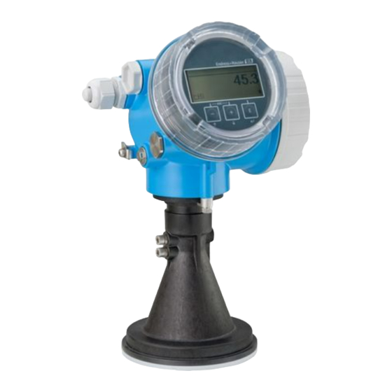
Product description Micropilot FMR56, FMR57 FOUNDATION Fieldbus Product description Product design 3.1.1 Micropilot FMR56 A0016791 1 Design of the Micropilot FMR56 (26 GHz) Electronics housing Horn 80mm/100 mm (3in/4in), PP cladded Flange Mounting bracket Endress+Hauser... - Page 9 Micropilot FMR56, FMR57 FOUNDATION Fieldbus Product description 3.1.2 Micropilot FMR57 A0016807 2 Design of the Micropilot FMR57 (26 GHz) Electronics housing Process connection (Thread) Horn antenna Flange Antenna extension Alignment device Parabolic antenna Endress+Hauser...
- Page 10 Electronics housing A0012422 3 Design of the electronics housing Electronics compartment cover Display module Main electronics module Cable glands (1 or 2, depending on instrument version) Nameplate I/O electronics module Terminals (pluggable spring terminals) Connection compartment cover Grounding terminal Endress+Hauser...
-
Page 11: Incoming Acceptance And Product Identification
Micropilot FMR56, FMR57 FOUNDATION Fieldbus Incoming acceptance and product identification Incoming acceptance and product identification Incoming acceptance DELIVERY NOTE 1 = 2 A0013696 A0016870 A0016871 A0013696 A0016872 Endress+Hauser... - Page 12 Incoming acceptance and product identification Micropilot FMR56, FMR57 FOUNDATION Fieldbus Made in Germany, 79689 Maulburg DELIVERY NOTE A0013696 A0014038 A0013696 A0014037 If one of the conditions does not comply, contact your Endress+Hauser distributor. Endress+Hauser...
-
Page 13: Product Identification
Only 33 digits of the extended order code can be indicated on the nameplate. If the extended order code exceeds 33 digits, the rest will not be shown. However, the complete extended order code can be viewed in the operating menu of the device (Diagnostics → Device info → Extended order code 1/2/3). Endress+Hauser... -
Page 14: Storage, Transport
Do not fasten lifting devices (hoisting slings, lifting eyes etc.) at the housing or the antenna horn but at the process connection. Take into account the mass center of the device in order to avoid unintended tilting. ‣ Comply with the safety instructions, transport conditions for devices over 18kg (39.6lbs). A0016875 Endress+Hauser... -
Page 15: Installation
• It is recommended to us a weather protection cover (1) in order to protect the device from direct sun or rain. • In extremely dusty applications, the integrated air purge connection can prevent clogging of the antenna A0016883 (→ 34). Endress+Hauser... - Page 16 Installation Micropilot FMR56, FMR57 FOUNDATION Fieldbus 6.1.2 Vessel installations Avoid any installations (limit switches, temperature sensors, braces etc.) inside the signal beam. Take into account the beam angle (→ 20): A0018946 Endress+Hauser...
- Page 17 (e.g. metallic pipes (1), ladders (2), grates (3), ...). Therefore, there should be no such interfering installations in the signal beam. Please contact Endress+Hauser for further information. Endress+Hauser...
- Page 18 Installation Micropilot FMR56, FMR57 FOUNDATION Fieldbus A0017125 Endress+Hauser...
- Page 19 In FMR57 with alignment device, the sensor can be optimally aimed within the vessel and thus interference echoes can be avoided. The maximum angle β is ±15°. In particular, sensor alignment serves to: – prevent interference reflections – extend the maximum possible measuring range in conical outlets Endress+Hauser...
- Page 20 2.80 m (9.2 ft) 25 m (82 ft) 4.37 m (14 ft) 3.50 m (11 ft) 30 m (98 ft) 5.25 m (17 ft) 4.20 m (14 ft) FMR57 - Horn antenna Antenna size 80 mm (3 in) 100 mm (4 in) Endress+Hauser...
- Page 21 2.44 m (8 ft) 50 m (164 ft) 3.50 m (11 ft) 3.06 m (10 ft) 60 m (197 ft) 4.19 m (14 ft) 3.70 m (12 ft) 70 m (230 ft) 4.90 m (16 ft) 4.28 m (14 ft) Endress+Hauser...
-
Page 22: Measuring Conditions
(high DC value, flat angle of repose) are met, shorter distances can be achieved. 100% A0016916 Dielectric constants of important media commonly used in the industry are summarized in the document SD106F, which can be downloaded from the Endress+Hauser web page (www.endress.com). Endress+Hauser... - Page 23 Micropilot FMR56, FMR57 FOUNDATION Fieldbus Installation Device A [mm (in)] C [mm (in)] FMR56 400(15.7) 50 to 150(1.97 to 5.91) FMR57 Endress+Hauser...
-
Page 24: Installation In Vessel (Free Space)
• A marking at the boss enables alignment of the antenna. This marking must be aligned towards the tank wall as well as possible. ° ° ° A0019434 Depending on the device version the marking may be a circle or two short parallel lines. Endress+Hauser... - Page 25 100 mm (3.94 in) 150 mm (5.91 in) 100 mm (3.94 in) 150 mm (5.91 in) < < < < < 500 mm (19.7 in) 500 mm (19.7 in) 500 mm (19.7 in) 500 mm (19.7 in) 500 mm (19.7 in) Endress+Hauser...
- Page 26 Align the antenna vertically to the product surface using the mounting bracket. NOTICE The mounting bracket has no conductive connection to the transmitter housing. Danger of electrostatic charge ‣ Connect the mounting bracket to the local potential equalization system. Endress+Hauser...
- Page 27 Depending on the device version the marking may be a circle or two short parallel lines. Nozzle mounting The horn antenna should protrude from the nozzle. If this is not possible for mechanical reasons, larger nozzle heights can be accepted. Endress+Hauser...
- Page 28 95 mm (3.74 in) < 260 mm (10.2 in) < 480 mm (18.9 in) without antenna extension Please contact Endress+Hauser for applications with higher nozzle. Threaded connection • Tighten with the hexagonal nut only. • Tool : Hexagonal wrench 60 mm •...
- Page 29 Antenna protrudes from the nozzle Antenna completely within the nozzle Antenna size 200 mm (8 in) 250 mm (10 in) 173 mm (6.81 in) 236 mm (9.29 in) < 50 mm (1.97 in) < 50 mm (1.97 in) without antenna extension Endress+Hauser...
- Page 30 173 mm (6.81 in) < 50 mm (1.96 in) 250 mm (10 in) 236 mm (9.29 in) < 50 mm (1.96 in) without antenna extension Installation with hinged flange At hinged flanges, the length of the antenna must be taken into account. Endress+Hauser...
- Page 31 Micropilot FMR56, FMR57 FOUNDATION Fieldbus Installation A0018878 Dismantling the parabolic reflector For installation in a nozzle, the parabolic reflector can be dismantled: Endress+Hauser...
- Page 32 Installation Micropilot FMR56, FMR57 FOUNDATION Fieldbus A0018877 Parabolic reflector 4 bolts; torque: 3 Nm (2,2 lbf ft) Endress+Hauser...
- Page 33 Using the alignment device it is possible to tilt the antenna axis by up to 15° in all directions. The alignment device is used for the optimum alignment of the radar beam with the bulk solids surface. Product structure: Feature 100 "Process connection", options XCJ, XEJ, XFJ A0016931 10 Micropilot FMR57 with alignment device Endress+Hauser...
- Page 34 • min. torque: 6 Nm (4.4 lbf ft) • max. torque: 7 Nm (5.2 lbf ft) Make sure to use dry purge air. In general, air purging should only be used as much as necessary, since too much air purging may cause mechanical damage (abrasion). Endress+Hauser...
-
Page 35: Vessels With Heat Insulation
To provide easier access to the connection compartment or display module, the transmitter housing can be turned: max. 350° 8 mm 8 mm A0013713 Unscrew the securing screw using an open-ended wrench. Rotate the housing in the desired direction. Endress+Hauser... -
Page 36: Turning The Display Module
Does the device conform to the measuring point specifications? For example: • Process temperature • Process pressure (refer to the chapter on "Material load curves" of the "Technical Information" document) • Ambient temperature range • Measuring range Are the measuring point identification and labeling correct (visual inspection)? Endress+Hauser... - Page 37 Micropilot FMR56, FMR57 FOUNDATION Fieldbus Installation Is the device adequately protected from precipitation and direct sunlight? Are the securing screw and securing clamp tightened securely? Endress+Hauser...
-
Page 38: Electrical Connection
≥60 °C (140 °F): use cable for temperature T +20 K. FOUNDATION Fieldbus Endress+Hauser recommends using twisted, shielded two-wire cables. For further information on the cable specifications, see Operating Instructions BA00013S "FOUNDATION Fieldbus Overview", FOUNDATION Fieldbus Guideline and IEC 61158-2 (MBP). - Page 39 Without integrated overvoltage protection With integrated overvoltage protection Cable screen: Observe cable specifications Switch output (open collector): Terminals 3 and 4 PROFIBUS PA / FOUNDATION Fieldbus: Terminals 1 and 2 Terminal for potential equalization line Cable entries Overvoltage protection module Endress+Hauser...
- Page 40 13 Connection of a relay 14 Connection of a digital input Pull-up resistor Suitable relays (examples): Digital input • Solid-state relay: Phoenix Contact OV-24DC/480AC/5 with mounting rail connector UMK-1 OM-R/AMS • Electromechanical relay: Phoenix Contact PLC- RSC-12DC/21 Endress+Hauser...
- Page 41 For the versions with fieldbus plug connector (M12 or 7/8"), the signal line can be connected without opening the housing. Pin assignment of the M12 plug connector Meaning Signal + not connected Signal - Ground A0011175 Pin assignment of the 7/8" plug connector Meaning Signal - Signal + Screen Not connected A0011176 Endress+Hauser...
- Page 42 • Ex ia + Ex d(ia) / IS + XP Feature 020 of the product structure Feature 010 of the product structure Input voltages up to 35 V will not spoil the device. Polarity sensitive FISCO/FNICO compliant according to IEC 60079-27 Endress+Hauser...
- Page 43 < 1.5 pF Nominal arrest impulse voltage (⁸⁄₂₀ μs) 10 kA External overvoltage protection HAW562 or HAW569 from Endress+Hauser are suited as external overvoltage protection. For detailed information please refer to the following documents: • HAW562: TI01012K • HAW569: TI01013K...
-
Page 44: Connecting The Measuring Device
Push the cable through the cable entry. To ensure tight sealing, do not remove the sealing ring from the cable entry. Strip the cable. Strip the cable ends 10 mm (0.4 in). For stranded cables, also attach wire end ferrules. Firmly tighten the cable glands. Endress+Hauser... - Page 45 Rigid conductors or flexible conductors with cable sleeve can directly be inserted and are contacted automatically. To remove cables from the terminal: Press on the groove between the terminals using a flat-tip screwdriver ≤ 3 mm (0.12 inch) while pulling the cables out of the terminals. Endress+Hauser...
- Page 46 Electrical connection Micropilot FMR56, FMR57 FOUNDATION Fieldbus ≤ 3 (0.12) mm (in) A0013661 Endress+Hauser...
-
Page 47: Post-Connection Check
– Device Description format 4 : *sym, *ffo – Device Description format 5 : *sy5, *ff5 Information on the device-specific DD Manufacturer ID 0x452B48 Device Type 0x1028 Device Revision 0x01 DD Revision Information and files at: • www.endress.com CFF Revision • www.fieldbus.org Endress+Hauser... -
Page 48: Integration Into The Foundation Fieldbus Network
The device appears in the network display once you have started the FF configuration program and integrated the device into the network. The blocks available are displayed under the device name. If the device description has not yet been loaded, the blocks report "Unknown" or "(UNK)". Endress+Hauser... - Page 49 (DI) PID_ xxxxxxxxxxx (PID) ARITHMETIC_ xxxxxxxxxxx (AR) SIGNAL_CHAR_ xxxxxxxxxxx (SC) INPUT_SELECTOR_ xxxxxxxxxxx (ISEL) INTEGRATOR_ xxxxxxxxxxx (IT) ANALOG_ALARM_ xxxxxxxxxxx (AAL) A0020711 15 Typical display in a configuration program after the connection has been established Device name Serial number Endress+Hauser...
-
Page 50: Block Model
Endress+Hauser Guideline BA00062S. The guideline provides an overview of the standard function blocks that are described in FOUNDATION Fieldbus Specifications FF 890 - 894. It is designed to help operators use the blocks implemented in the Endress+Hauser field devices. Endress+Hauser... -
Page 51: Assignment Of The Measured Values (Channel) In An Ai Block
The input value of an Analog Input Block is defined by the CHANNEL parameter. Channel Measured value Uninitialized Terminal voltage Analog output advance diagnostics 1 Analog output advance diagnostics 2 32786 Absolute echo amplitude 32856 Distance 32885 Elektronic temperature Endress+Hauser... - Page 52 Integration into a FOUNDATION Fieldbus network Micropilot FMR56, FMR57 FOUNDATION Fieldbus Channel Measured value 32949 Level linearized 33044 Relative echo amplitude Endress+Hauser...
-
Page 53: Methods
This method is located in the ADV_SETUP Transducer Block and allows to manage the linearization table by which the measured value is converted into volume, mass or flow. • Self Check This method is located in the EXPERT_CONFIG Transducer Block and prompts the device self check parameters. Endress+Hauser... -
Page 54: Commissioning (Via Operating Menu)
Representation of a parameter (here: a parameter with selection list) 3.1 Header containing parameter name and error symbol (if an error is active) 3.2 Selection list; marks the current parameter value. Input matrix for numbers Input matrix for alphanumeric and special characters Endress+Hauser... - Page 55 Reduces the contrast (brighter setting). A0013953 Plus/Enter key combination (press and hold down the keys simultaneously) Increases the contrast (darker setting). A0013954 Minus/Plus/Enter key combination (press and hold down the keys simultaneously) For measured value display A0013955 Enables or disables the keypad lock. Endress+Hauser...
-
Page 56: Operating Menu
In case of operation via operating tools (e.g. FieldCare), the "Language" parameter is located at "Setup → Advanced Setup → Display" On entering the "Expert" menu, a access code is always requested. If a customer specific access code has not been defined, "0000" has to be entered. Endress+Hauser... -
Page 57: Unlock The Device
X X X X X X X 20.50 Main menu 0104-1 Language English Display/operat. Setup Language 0104-1 English à Deutsch Español Français Language 0104-1 à English Deutsch Español Français Hauptmenü 0104-1 Sprache Deutsch Anzeige/Betrieb Setup A0013996 18 Taking the example of the local display Endress+Hauser... -
Page 58: Configuration Of A Level Measurement
If, for example, the measuring range covers only an upper part of the tank (E << tank height), it is mandatory to enter the acutal tank height into the "Setup → Advanced Setup → Level → Tank/silo height" parameter. Endress+Hauser... - Page 59 12. Setup → Advanced setup →Level → Level unit Select level unit: %, m, mm, ft, in (Factory setting: %) It is strongly recommended to adjust the maximum filling and draining speed to the actual process. Endress+Hauser...
-
Page 60: User-Specific Applications
If necessary, change the block name. Set the block mode to OOS by means of the Block Mode/MODE_BLK parameter, TARGET element. Configure the level measurement (→ 64). Set the block mode to Auto by means of the Block Mode/MODE_BLK parameter, TARGET element. Endress+Hauser... - Page 61 Set the block mode to Auto using the Block Mode/MODE_BLK parameter, TARGET element. For this purpose, the Resource Block and the Setup Transducer Block must also be set to the Auto block mode. 10.1.5 Additional configuration Link the function blocks and output blocks. Endress+Hauser...
-
Page 62: Scaling Of The Measured Value In An Ai Block
• If you have selected the Direct mode for the L_TYPE parameter, you cannot change the values and units for XD_SCALE and OUT_SCALE. • The L_TYPE, XD_SCALE and OUT_SCALE parameters can only be changed in the OOS block mode. Endress+Hauser... -
Page 63: Language Selection
• 33062: Russian • 33083: Spanish • 33103: Thai • 33120: Vietnamese • 33155: Bahasa • 33166: Turkish When ordering a device the set of available languages is defined. Refer to the product structure, feature 500 "Additional Operation Language". Endress+Hauser... -
Page 64: Configuration Of A Level Measurement
The Setup method can also be used to configure the measurement. It is called up via the SETUP (TRDSUP) Transducer Block. 100% A0016934 R = Reference point of the measurement E = Empty calibration (= Zero point) D = Distance F = Full calibration (= span) L = Level Endress+Hauser... - Page 65 0,5m (1.6ft) /h • 724: Slow < 1 m (3.3ft) /h • 725: Medium < 4m (13ft) /h • 726: Fast < 8m (26ft) /h • 727: Very fast > 8m (26ft) /h • 33442: No filter / test Endress+Hauser...
- Page 66 Selection: • 179: Manual • 32847: Factory • 32859: Distance • 32860: Distance too big • 32861: Distance too small • 32862: Distance unknown • 33100: Tank empty Endress+Hauser...
- Page 67 HistoROM. 32848: Clear backup data The backup copy of the device configuration is deleted from the display module of the device. HistoROM A HistoROM is a "non-volatile" device memory in the form of an EEPROM. Endress+Hauser...
- Page 68 Commissioning (block-based operation) Micropilot FMR56, FMR57 FOUNDATION Fieldbus While this action is in progress, the configuration cannot be edited via the local display and a message on the processing status appears on the display. Endress+Hauser...
- Page 72 *71219986* 71219986 www.addresses.endress.com...