Endress+Hauser Micropilot FMR56 Brief Operating Instructions
Free space radar
Hide thumbs
Also See for Micropilot FMR56:
- Operating instructions manual (198 pages) ,
- Technical information (103 pages) ,
- Brief operating instructions (72 pages)
Table of Contents
Advertisement
Quick Links
KA01102F/00/EN/03.15
71282542
Products
Brief Operating Instructions
Micropilot FMR56, FMR57
HART
Free space radar
These Instructions are Brief Operating Instructions; they are
not a substitute for the Operating Instructions pertaining to
the device.
Detailed information about the device can be found in the
Operating Instructions and the other documentation:
Available for all device versions via:
– Internet:
www.endress.com/deviceviewer
– Smart phone/tablet: Endress+Hauser Operations App
Solutions
Services
Advertisement
Table of Contents

Related Manuals for Endress+Hauser Micropilot FMR56


Summary of Contents for Endress+Hauser Micropilot FMR56
- Page 1 Operating Instructions pertaining to the device. Detailed information about the device can be found in the Operating Instructions and the other documentation: Available for all device versions via: – Internet: www.endress.com/deviceviewer – Smart phone/tablet: Endress+Hauser Operations App...
- Page 2 Micropilot FMR56, FMR57 HART Order code 00X00-XXXX0XX0XXX Ser. No.: X000X000000 TAG No.: XXX000 Serial number www.endress.com/deviceviewer Endress+Hauser Operations App A0023555 Endress+Hauser...
-
Page 3: Table Of Contents
Micropilot FMR56, FMR57 HART Table of contents Table of contents Important document information ..........4 Symbols . -
Page 4: Important Document Information
Important document information Micropilot FMR56, FMR57 HART Important document information Symbols 1.1.1 Safety symbols Symbol Meaning DANGER! This symbol alerts you to a dangerous situation. Failure to avoid this situation will result in DANGER serious or fatal injury. WARNING! WARNING This symbol alerts you to a dangerous situation. - Page 5 Micropilot FMR56, FMR57 HART Important document information 1.1.4 Symbols for certain types of information Symbol Meaning Symbol Meaning Permitted Preferred Procedures, processes or actions that Procedures, processes or actions that are permitted. are preferred. Forbidden Procedures, processes or actions that Indicates additional information.
-
Page 6: Basic Safety Instructions
The manufacturer is not liable for damage caused by improper or non-designated use. Verification for borderline cases: ‣ For special measured materials and cleaning agents, Endress+Hauser is glad to provide assistance in verifying the corrosion resistance of wetted materials, but does not accept any warranty or liability. -
Page 7: Workplace Safety
It meets general safety standards and legal requirements. It also complies with the EC directives listed in the device-specific EC Declaration of Conformity. Endress+Hauser confirms this by affixing the CE mark to the device. Endress+Hauser... -
Page 8: Product Description
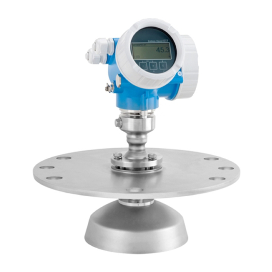
Product description Micropilot FMR56, FMR57 HART Product description Product design 3.1.1 Micropilot FMR56 A0016791 1 Design of the Micropilot FMR56 (26 GHz) Electronics housing Horn 80mm/100 mm (3in/4in), PP cladded Flange Mounting bracket Endress+Hauser... -
Page 9: Incoming Acceptance And Product Identification
• Do the nameplate data match the ordering information on the delivery note? • Is the DVD with the operating tool present? If required (see nameplate): Are the Safety Instructions (XA) present? If one of these conditions is not satisfied, contact your Endress+Hauser Sales Center. Endress+Hauser... -
Page 10: Product Identification
): All information about the measuring device is displayed. • Enter the serial number from the nameplates into the Endress+Hauser Operations App or scan the 2-D matrix code (QR code) on the nameplate with the Endress+Hauser Operations App: all the information for the measuring device is displayed. -
Page 11: Storage, Transport
Micropilot FMR56, FMR57 HART Storage, Transport Storage, Transport Storage conditions • Permitted storage temperature: –40 to +80 °C (–40 to +176 °F) • Use the original packaging. Transport product to the measuring point NOTICE Housing or antenna horn may be damaged or break away. -
Page 12: Installation
Installation Micropilot FMR56, FMR57 HART Installation Installation conditions 6.1.1 Mounting position • Recommended distance A from wall to outer edge of nozzle: ~ 1/6 of vessel diameter. Nevertheless the device should not be installed closer than 20 cm (7.87 in) to the vessel wall. - Page 13 Micropilot FMR56, FMR57 HART Installation 6.1.2 Vessel installations Avoid any installations (limit switches, temperature sensors, braces etc.) inside the signal beam. Take into account the beam angle → 16. A0018946 Endress+Hauser...
- Page 14 If the outer wall of the vessel is made of a non-conductive material (e.g. GRP), microwaves can also be reflected off interfering installations outside the signal beam (e.g. metallic pipes (1), ladders (2), grates (3), ...). Therefore, there should be no such interfering installations in the signal beam. Please contact Endress+Hauser for further information. Endress+Hauser...
- Page 15 Micropilot FMR56, FMR57 HART Installation A0017125 6.1.5 Optimization options • Antenna size The bigger the antenna, the smaller the beam angle α and the fewer interference echoes → 16. • Mapping The measurement can be optimized by means of electronic suppression of interference echoes.
- Page 16 Installation Micropilot FMR56, FMR57 HART • Metallic screens mounted at a slope They spread the radar signals and can, therefore, reduce interference echoes. • Variable flange seal (FMR56) Using the variable flange seal, the device can be aligned in the direction of the product surface.
- Page 17 Micropilot FMR56, FMR57 HART Installation Beam diameter W as a function of beam angle α and measuring distance D: FMR56 Antenna size 80 mm (3 in) 100 mm (4 in) Beam angle α 10° 8° Measuring distance (D) Beamwidth diameter (W) 3 m (9.8 ft)
-
Page 18: Measuring Conditions
(high DC value, flat angle of repose) are met, shorter distances can be achieved. Dielectric constants of important media commonly used in various industries are summarized in the DC manual (CP01076F) and in the Endress+Hauser "DC Values App" (available for Android and iOS). Endress+Hauser... -
Page 19: Installation In Vessel (Free Space)
Micropilot FMR56, FMR57 HART Installation 100% A0016916 Device A [mm (in)] C [mm (in)] FMR56 400(15.7) 50 to 150(1.97 to 5.91) FMR57 Installation in vessel (free space) 6.3.1 Horn antenna with slip-on flange (FMR56) Alignment When using the Micropilot with a slip-on flange in explosion-hazardous areas, strictly observe all specifications in the relevant Safety Instructions (XA). - Page 20 Installation Micropilot FMR56, FMR57 HART ° ° ° A0019434 Depending on the device version the marking may be a circle or two short parallel lines. Nozzle mounting øD A0016868 5 Nozzle height and diameter for horn antenna with slip-on flange...
- Page 21 Micropilot FMR56, FMR57 HART Installation 6.3.2 Horn antenna with mounting bracket (FMR56) A0016865 6 Installation of the horn antenna with mounting bracket Align the antenna vertically to the product surface using the mounting bracket. NOTICE The mounting bracket has no conductive connection to the transmitter housing.
- Page 22 Installation Micropilot FMR56, FMR57 HART ° ° ° A0019434 Depending on the device version the marking may be a circle or two short parallel lines. Nozzle mounting The horn antenna should protrude from the nozzle. If this is not possible for mechanical reasons, larger nozzle heights can be accepted.
- Page 23 480 mm (18.9 in) Feature 070 of the product structure valid for antennas without antenna extension Please contact Endress+Hauser for applications with higher nozzle. Threaded connection For devices with a threaded connection it may be necessary - depending on the antenna size - to unmount the horn before fastening the device and to mount it again afterwards.
- Page 24 Installation Micropilot FMR56, FMR57 HART øD A0016827 8 Nozzle mounting of Micropilot FMR57 with parabolic antenna Antenna protrudes from the nozzle Antenna completely within the nozzle Antenn Antenna diameter D Nozzle height H for case 1 Maximum nozzle height H for case FA: Parabol 200mm/8"...
- Page 25 Micropilot FMR56, FMR57 HART Installation Standard installation øD A0018874 Nozzle Antenna size D 200 mm (8 in) 173 mm (6.81 in) < 50 mm (1.96 in) 250 mm (10 in) 236 mm (9.29 in) < 50 mm (1.96 in) without antenna extension Installation with hinged flange At hinged flanges, the length of the antenna must be taken into account.
- Page 26 Installation Micropilot FMR56, FMR57 HART A0018878 6.3.5 Alignment device for FMR57 Using the alignment device it is possible to tilt the antenna axis by up to 15° in all directions. The alignment device is used for the optimum alignment of the radar beam with the bulk solids surface.
- Page 27 Micropilot FMR56, FMR57 HART Installation Align antenna axis: Loosen screws. Align antenna axis (up to. ± 15° in all directions). Tighten screws with 15 Nm (11 lbf ft). 6.3.6 Integrated air purge connection for FMR57 In extremely dusty applications, the integrated air purge connection can prevent clogging of the antenna.
-
Page 28: Vessels With Heat Insulation
Installation Micropilot FMR56, FMR57 HART Vessels with heat insulation A0019142 If process temperatures are high, the device must be included in normal tank insulation to prevent the electronics heating up as a result of heat radiation or convection. The insulation may not exceed beyond the neck of the housing. -
Page 29: Turning The Display Module
Micropilot FMR56, FMR57 HART Installation Turning the display module 3 mm A0013905 If present: Loosen the screw of the securing clamp of the electronics compartment cover using an Allen key and turn the clamp 90° conterclockwise. Unscrew cover of the electronics compartment from the transmitter housing. -
Page 30: Electrical Connection
Electrical connection Micropilot FMR56, FMR57 HART Electrical connection Connection conditions 7.1.1 Terminal assignment 2-wire: 4-20mA HART – – 4...20 mA – – 4...20 mA A0011294 11 Terminal assignment 2-wire; 4-20mA HART Without integrated overvoltage protection With integrated overvoltage protection Active barrier with power supply (e.g. - Page 31 Micropilot FMR56, FMR57 HART Electrical connection Analog display device: Observe maximum load Cable screen; observe cable specification 4-20mA HART (passive): Terminals 1 and 2 Overvoltage protection module Terminal for potential equalization line Cable entry Endress+Hauser...
- Page 32 Electrical connection Micropilot FMR56, FMR57 HART 2-wire: 4-20mA HART, switch output – 4...20 mA ³ – 4...20 mA ³ A0013759 12 Terminal assignment 2-wire; 4-20mA HART, switch output Without integrated overvoltage protection With integrated overvoltage protection Active barrier with power supply (e.g. RN221N): Observe terminal voltage HART communication resistor (≥250 Ω): Observe maximum load...
- Page 33 Micropilot FMR56, FMR57 HART Electrical connection Cable entry for 4-20mA HART line Cable entry for switch output line Overvoltage protection module Endress+Hauser...
- Page 34 Electrical connection Micropilot FMR56, FMR57 HART 2-wire: 4-20mA HART, 4-20mA – 4...20 mA – 4...20 mA – 4...20 mA – 4...20 mA A0013923 13 Terminal assignment 2-wire, 4-20 mA HART, 4...20mA Without integrated overvoltage protection With integrated overvoltage protection...
- Page 35 Micropilot FMR56, FMR57 HART Electrical connection Analog display device ; observe maximum load Analog display device ; observe maximum load Supply voltage for current output 2 (e.g. RN221N); Obeserve terminal voltage Overvoltage protection module Current output 2: Terminals 3 and 4...
- Page 36 Electrical connection Micropilot FMR56, FMR57 HART 4-wire: 4-20mA HART (10.4 to 48 V 4...20 mA ³ A0011340 14 Terminal assignment 4-wire; 4-20mA HART (10.4 to 48 VDC) Evaluation unit, e.g. PLC HART communication resistor (≥250 Ω): Observe maximum load...
- Page 37 Micropilot FMR56, FMR57 HART Electrical connection 4-wire: 4-20mA HART (90 to 253 V 4...20 mA ³ A0018965 15 Terminal assignment 4-wire; 4-20mA HART (90 to 253 VAC) Evaluation unit, e.g. PLC HART communication resistor (≥250 Ω): Observe maximum load...
- Page 38 Electrical connection Micropilot FMR56, FMR57 HART CAUTION To ensure electrical safety: ‣ Do not disconnect the protective connection (6). ‣ Disconnect the supply voltage before disconnecting the protective earth (7). Connect protective earth to the internal ground terminal (7) before connecting the supply voltage.
- Page 39 Micropilot FMR56, FMR57 HART Electrical connection 7.1.2 Device plug connectors For the versions with fieldbus plug connector (M12 or 7/8"), the signal line can be connected without opening the housing. Pin assignment of the M12 plug connector Meaning Signal +...
- Page 40 Electrical connection Micropilot FMR56, FMR57 HART 7.1.3 Supply voltage 2-wire, 4-20mA HART, passive "Power "Approval" Terminal Maximum load R, depending on the supply voltage U at the supply Supply, voltage U unit Output" at the device A: 2-wire; • Non-Ex 10.4 to...
- Page 41 Micropilot FMR56, FMR57 HART Electrical connection "Power "Approval" Terminal Maximum load R, depending on the supply voltage U at the supply Supply, voltage U unit Output" at the device B: 2-wire; • Non-Ex 12 to R [ ] W 4-20 mA •...
- Page 42 Electrical connection Micropilot FMR56, FMR57 HART Polarity reversal protection Admissible residual ripple at < 1 V f = 0 to 100 Hz Admissible residual ripple at < 10 mV f = 100 to 10000 Hz Endress+Hauser...
- Page 43 < 1.5 pF Nominal arrest impulse voltage (8/20 μs) 10 kA External overvoltage protection HAW562 or HAW569 from Endress+Hauser are suited as external overvoltage protection. For detailed information please refer to the following documents: • HAW562: TI01012K • HAW569: TI01013K...
-
Page 44: Connecting The Device
Electrical connection Micropilot FMR56, FMR57 HART Connecting the device WARNING Explosion hazard! ‣ Comply with the relevant national standards. ‣ Observe the specifications in the Safety Instructions (XA). ‣ Only use the specified cable glands. ‣ Check whether the supply voltage matches the specifications on the nameplate. - Page 45 Micropilot FMR56, FMR57 HART Electrical connection A0013837 Connect the cable in accordance with the terminal assignment → 30. When using screened cable: Connect the cable screen to the ground terminal. Screw the cover onto the connection compartment. 10. For instruments with safety pin for the lid: Adjust the safety pin so that its edge is over the edge of the display lid.
-
Page 46: Post-Connection Check
Electrical connection Micropilot FMR56, FMR57 HART Post-connection check Are cables or the device undamaged (visual inspection)? Do the cables comply with the requirements? Do the cables have adequate strain relief? Are all cable glands installed, firmly tightened and correctly sealed? Does the supply voltage match the specifications on the transmitter nameplate? Is the terminal assignment correct →... -
Page 47: Commissioning (Via Operating Menu)
Micropilot FMR56, FMR57 HART Commissioning (via operating menu) Commissioning (via operating menu) Display and operating module 8.1.1 Display appearance User ABC_ DEFG HIJK LMNO PQRS TUVW A0012635 16 Appearance of the display and operation module for on-site operation Measured value display (1 value max. size) 1.1 Header containing tag and error symbol (if an error is active) - Page 48 Commissioning (via operating menu) Micropilot FMR56, FMR57 HART 8.1.2 Operating elements Meaning Minus key For menu, submenu Moves the selection bar upwards in a picklist. A0013969 For text and numeric editor In the input mask, moves the selection bar to the left (backwards).
- Page 49 Micropilot FMR56, FMR57 HART Commissioning (via operating menu) 8.1.3 Opening the context menu Using the context menu, the user can call up the following menus quickly and directly from the operational display: • Setup • Conf. backup disp. • Simulation Calling up and closing the context menu The user is in the operational display.
-
Page 50: Operating Menu
Commissioning (via operating menu) Micropilot FMR56, FMR57 HART Operating menu Parameter/Submenu Meaning Description Language Defines the operating language of the on-site display. Setup When appropriate values have been assigned toall setup parameters, the measured should be completely configured in a standard application. -
Page 51: Unlock The Device
Micropilot FMR56, FMR57 HART Commissioning (via operating menu) Unlock the device If the device has been locked, it must be unlocked before the measurement can be configured. For details refer to the Operating Instructions of the device: BA01048F (FMR56/FMR57, HART) -
Page 52: Configuration Of A Level Measurement
Commissioning (via operating menu) Micropilot FMR56, FMR57 HART Configuration of a level measurement 100% A0016934 Setup → Device tag Enter device tag. Setup → Distance unit Select distance unit. Setup → Bin type Select bin type. Setup → Max. filling speed solid ... -
Page 53: User-Specific Applications
Micropilot FMR56, FMR57 HART Commissioning (via operating menu) Setup → Level Indicates the measrued level L. Setup → Distance Indicates the measured distance from the reference point R to the level L. 10. Setup → Signal quality Indicates the quality of the evaluated level echo. - Page 56 *71282542* 71282542 www.addresses.endress.com...