Endress+Hauser Micropilot FMR56 Technical Information
Level radar
Hide thumbs
Also See for Micropilot FMR56:
- Operating instructions manual (198 pages) ,
- Technical information (103 pages) ,
- Brief operating instructions (72 pages)
Table of Contents
Advertisement
Quick Links
TI01042F/00/EN/03.13
71224360
Products
Technical Information
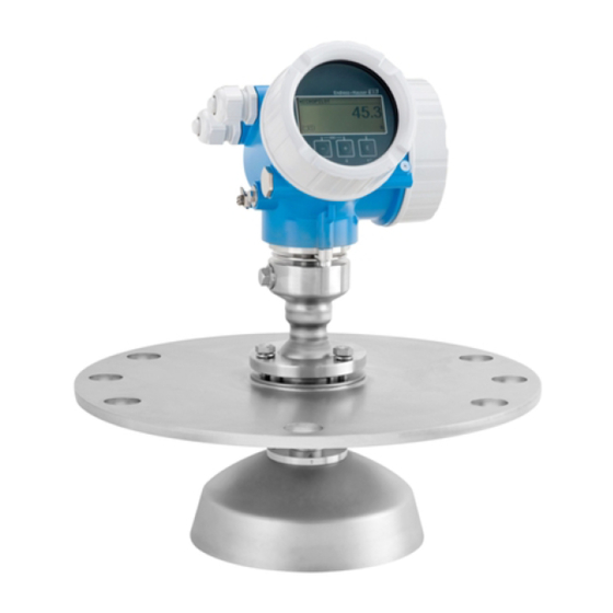
Micropilot FMR56, FMR57
Level radar
Level measurement in bulk solids
Application
Continuous, non-contact level measurement in powdery to granular bulk solids
Features FMR56:
• Attractively-priced basic device for standard process conditions (e.g. bulk cargo
silos, bulk storage tanks)
• PP-cladded horn antenna
• Maximum measuring range: 30 m (98 ft)
• Mounting bracket or variable flange seal for alignment
• Temperature range: –40 to +80 °C (–40 to 176 °F)
• Pressure range: –1 to +3 bar (–14.5 to +43.5 psi)
• Accuracy: ±3 mm
Features FMR57:
• For highly demanding solid applications (e.g. high silos, bunkers, stockpiles)
• Horn or parabolic antenna
• Air purge connection integrated
• Maximum measuring range: 70 m (230 ft)
• Temperature range: –40 to +400 °C (–40 to 752 °F)
• Pressure range: –1 to +16 bar (–14.5 to +232 psi)
• Accuracy: ±3 mm
Your benefits
• Reliable even under changing product and process conditions
• Integrated data memory (HistoROM) for high availability
• Intuitive operating menu in national languages for easy commissioning
• Exact diagnostic and process information
• International approvals for use in hazardous areas
• 5-point linearity protocol
• SIL2 according to IEC 61508, SIL3 in case of homogeneous or heterogeneous
redundancy
• System integration via HART/PROFIBUS PA (Profile 3.02)/FOUNDATION Fieldbus
Solutions
Services
Advertisement
Table of Contents

Related Manuals for Endress+Hauser Micropilot FMR56


Summary of Contents for Endress+Hauser Micropilot FMR56
- Page 1 Products Solutions Services TI01042F/00/EN/03.13 71224360 Technical Information Micropilot FMR56, FMR57 Level radar Level measurement in bulk solids Application Continuous, non-contact level measurement in powdery to granular bulk solids Features FMR56: • Attractively-priced basic device for standard process conditions (e.g. bulk cargo silos, bulk storage tanks) •...
-
Page 2: Table Of Contents
Micropilot FMR56, FMR57 Table of contents Important document information ....3 Process ........54 Document conventions . -
Page 3: Important Document Information
Micropilot FMR56, FMR57 Important document information Document conventions Safety symbols Symbol Meaning DANGER! DANGER This symbol alerts you to a dangerous situation. Failure to avoid this situation will result in serious or fatal injury. A0011189-EN WARNING! WARNING This symbol alerts you to a dangerous situation. Failure to avoid this situation can result in serious or fatal injury. - Page 4 Micropilot FMR56, FMR57 Symbol Meaning Reference to page Refers to the corresponding page number. A0011195 Reference to graphic Refers to the corresponding graphic number and page number. A0011196 Symbols in graphics Symbol Meaning 1, 2, 3 ... Item numbers Series of steps …...
-
Page 5: Function And System Design
Micropilot FMR56, FMR57 Function and system design Measuring principle The Micropilot is a "downward-looking" measuring system, operating based on the time-of-flight method (ToF). It measures the distance from the reference point (process connection) to the product surface. Radar impulses are emitted by an antenna, reflected off the product surface and received again by the radar system. - Page 6 • Measurement unaffected by medium properties • Hardware and software developed according to SIL IEC 61508 Procurement • Endress+Hauser being the world market leader in level measurement guarantees asset protection • Worldwide support and service Installation • Special tools are not required •...
-
Page 7: Input
Micropilot FMR56, FMR57 Input Measured variable The measured variable is the distance between the reference point and the product surface. The level is calculated from this distance, taking into account the empty distance "E" entered by the user. If required, the level can be converted into other variables (volume, mass) by means of a linearization (up to 32 points). -
Page 8: Operating Frequency
Micropilot FMR56, FMR57 Operating frequency K-band (~ 26 GHz) Up to 8 Micropilot transmitters can be installed in the same tank because the transmitter pulses are statistically coded. Transmitting power Distance Average energy density in beam direction 1 m (3.3 ft) <... -
Page 9: Output
Micropilot FMR56, FMR57 Output Output signal HART Signal coding FSK ±0.5 mA over current signal Data transmission rate 1 200 Bit/s Galvanic isolation PROFIBUS PA Signal coding Manchester Bus Powered (MBP) Data transmission rate 31.25 kBit/s, voltage mode Galvanic isolation... -
Page 10: Signal On Alarm
Micropilot FMR56, FMR57 Signal on alarm Depending on the interface, failure information is displayed as follows: • Current output (for HART devices) – Failsafe mode selectable (in accordance with NAMUR Recommendation NE 43): Minimum alarm: 3.6 mA Maximum alarm (= factory setting): 22 mA –... - Page 11 Micropilot FMR56, FMR57 Output values Analog Input: • Level linearized • Distance • Terminal voltage • Electronic temperature • Absolute echo amplitude • Relative echo amplitude • Analog output advanced diagnostics 1/2 Digital Input: • Advanced diagnostic blocks • Status output switch block...
- Page 12 Contains parameters which allow to backup the no output values Block device configuration in the display module and to restore it into the device. Access to these parameters is restricted to the Endress+Hauser service. depending on the configuration of the block Endress+Hauser...
- Page 13 Micropilot FMR56, FMR57 Function Blocks Block Content Number of Number of Execution Functionality permanent instantiable time blocks blocks Resource Block The Resource Block contains all the enhanced data that uniquely identifies the field device. It is an electronic version of a nameplate of the device.
- Page 14 Micropilot FMR56, FMR57 Block Content Number of Number of Execution Functionality permanent instantiable time blocks blocks Integrator The Integrator Function Block 25 ms standard Block integrates a variable as a function of the time or accumulates the counts from a Pulse Input block.
-
Page 15: Power Supply
Micropilot FMR56, FMR57 Power supply Terminal assignment 2-wire: 4-20mA HART – – 4...20 mA – – 4...20 mA A0011294 3 Terminal assignment 2-wire; 4-20mA HART Without integrated overvoltage protection With integrated overvoltage protection Active barrier with power supply (e.g. RN221N): Observe terminal voltage (→ 23) HART communication resistor (≥250 Ω): Observe maximum load (→... - Page 16 Micropilot FMR56, FMR57 2-wire: 4-20mA HART, switch output – 4...20 mA ³ – 4...20 mA ³ A0013759 4 Terminal assignment 2-wire; 4-20mA HART, switch output Without integrated overvoltage protection With integrated overvoltage protection Active barrier with power supply (e.g. RN221N): Observe terminal voltage (→ 23) HART communication resistor (≥250 Ω): Observe maximum load (→...
- Page 17 Micropilot FMR56, FMR57 2-wire: 4-20mA HART, 4-20mA – 4...20 mA – 4...20 mA – 4...20 mA – 4...20 mA A0013923 5 Terminal assignment 2-wire, 4-20 mA HART, 4...20mA Without integrated overvoltage protection With integrated overvoltage protection Connection current output 2 Connection current output 1 Supply voltage for current output 1 (e.g.
- Page 18 Micropilot FMR56, FMR57 4-wire: 4-20mA HART (10.4 to 48 V 4...20 mA ³ A0011340 6 Terminal assignment 4-wire; 4-20mA HART (10.4 to 48 VDC) Evaluation unit, e.g. PLC HART communication resistor (≥250 Ω): Observe maximum load (→ 25) Connection for Commubox FXA195 or FieldXpert SFX100 (via VIATOR Bluetooth modem) Analog display device: Observe maximum load (→...
- Page 19 Micropilot FMR56, FMR57 4-wire: 4-20mA HART (90 to 253 V 4...20 mA ³ A0018965 7 Terminal assignment 4-wire; 4-20mA HART (90 to 253 VAC) Evaluation unit, e.g. PLC HART communication resistor (≥250 Ω): Observe maximum load (→ 25) Connection for Commubox FXA195 or FieldXpert SFX100 (via VIATOR Bluetooth modem) Analog display device: Observe maximum load (→...
- Page 20 Micropilot FMR56, FMR57 PROFIBUS PA / FOUNDATION Fieldbus A0011341 8 Terminal assignment PROFIBUS PA / FOUNDATION Fieldbus Without integrated overvoltage protection With integrated overvoltage protection Cable screen: Observe cable specifications Switch output (open collector): Terminals 3 and 4 PROFIBUS PA / FOUNDATION Fieldbus: Terminals 1 and 2...
- Page 21 Micropilot FMR56, FMR57 Connection examples for the switch output For HART devices, the switch output is available as an option. See product structure, feature 20: "Power Supply, Output", option B: "2-wire; 4-20mA HART, switch output" Devices with PROFIBUS PA and FOUNDATION Fieldbus always have a switch output.
-
Page 22: Device Plug Connectors
Micropilot FMR56, FMR57 Device plug connectors For the versions with fieldbus plug connector (M12 or 7/8"), the signal line can be connected without opening the housing. Pin assignment of the M12 plug connector Meaning Signal + not connected Signal -... -
Page 23: Supply Voltage
Micropilot FMR56, FMR57 Supply voltage An external power supply is required. Various supply units can be ordered from Endress+Hauser: see "Accessories" section (→ 84) 2-wire, 4-20mA HART, passive "Power Supply, "Approval" Terminal voltage U at Maximum load R, depending on the supply voltage U at the Output"... - Page 24 Micropilot FMR56, FMR57 "Power Supply, Output" "Approval" Terminal voltage U at the Maximum load R, depending on the supply voltage U at the device supply unit C: 2-wire; 4-20mA HART, 12 to 30 V R [ ] ? 4-20mA U 0 [V]...
-
Page 25: Power Consumption
Micropilot FMR56, FMR57 4-wire, 4-20mA HART, active "Power supply; Output" Terminal voltage Maximum load R K: 4-wire 90-253VAC; 4-20mA HART 90 to 253 V (50 to 60 Hz), 500 Ω overvoltage category II L: 4-wire 10,4-48VDC; 4-20mA HART 10.4 to 48 V... -
Page 26: Power Supply Failure
"Guidelines for planning and commissioning PROFIBUS DP/PA", PNO Guideline 2.092 "PROFIBUS PA User and Installation Guideline" and IEC61158-2 (MBP). FOUNDATION Fieldbus Endress+Hauser recommends using twisted, shielded two-wire cables. For further information on the cable specifications, see Operating Instructions BA00013S "FOUNDATION Fieldbus Overview", FOUNDATION Fieldbus Guideline and IEC 61158-2 (MBP). -
Page 27: Overvoltage Protection
< 1.5 pF Nominal arrest impulse voltage (⁸⁄₂₀ μs) 10 kA External overvoltage protection HAW562 or HAW569 from Endress+Hauser are suited as external overvoltage protection. For detailed information please refer to the following documents: • HAW562: TI01012K • HAW569: TI01013K... -
Page 28: Performance Characteristics
Micropilot FMR56, FMR57 Performance characteristics Reference operating • Temperature = +24 °C (+75 °F)±5 °C (±9 °F) conditions • Pressure = 960 mbar abs. (14 psia)±100 mbar (±1.45 psi) • Humidity = 60 %±15 % • Reflector: metal plate with a minimum diameter of 1 m (40 in) •... -
Page 29: Reaction Time
Micropilot FMR56, FMR57 Reaction time The reaction time can be parametrized. The following step response times (as per DIN EN 61298-2) are valid if the damping is switched off: Tank height Sampling rate Step response time <10 m (33 ft) ≥3.6 s... -
Page 30: Installation
Micropilot FMR56, FMR57 Installation Installation conditions Mounting position • Recommended distance A from wall to outer edge of nozzle: ~ 1/6 of vessel diameter. Nevertheless the device should not be installed closer than 20 cm (7.87 in) to the vessel wall. - Page 31 Micropilot FMR56, FMR57 Vessel installations Avoid any installations (limit switches, temperature sensors, braces etc.) inside the signal beam. Take into account the beam angle (→ 35): A0018946 Endress+Hauser...
- Page 32 If the outer wall of the vessel is made of a non-conductive material (e.g. GRP), microwaves can also be reflected off interfering installations outside the signal beam (e.g. metallic pipes (1), ladders (2), grates (3), ...). Therefore, there should be no such interfering installations in the signal beam. Please contact Endress+Hauser for further information. Endress+Hauser...
- Page 33 Micropilot FMR56, FMR57 A0017125 Endress+Hauser...
- Page 34 Micropilot FMR56, FMR57 Optimization options • Antenna size The bigger the antenna, the smaller the beam angle α and the fewer interference echoes (→ 35). • Mapping The measurement can be optimized by means of electronic suppression of interference echoes.
- Page 35 Micropilot FMR56, FMR57 Beam angle A0016891 12 Relationship between beam angle α, distance D and beamwidth diameter W The beam angle is defined as the angle α where the energy density of the radar waves reaches half the value of the maximum energy density (3-dB-width). Microwaves are also emitted outside the signal beam and can be reflected off interfering installations.
- Page 36 Micropilot FMR56, FMR57 FMR57 - Parabolic antenna Antenna size 200 mm (8 in) 250 mm (10 in) Beam angle α 4° 3,5° Measuring distance (D) Beamwidth diameter W 5 m (16 ft) 0.35 m (1.1 ft) 0.30 m (1 ft) 10 m (33 ft) 0.70 m (2.3 ft)
-
Page 37: Measuring Conditions
A [mm (in)] C [mm (in)] FMR56 400(15.7) 50 to 150(1.97 to 5.91) FMR57 Dielectric constants of important media commonly used in the industry are summarized in the document SD106F, which can be downloaded from the Endress+Hauser web page (www.endress.com). Endress+Hauser... -
Page 38: Installation In Vessel (Free Space)
Micropilot FMR56, FMR57 Installation in vessel (free Horn antenna with slip-on flange (FMR56) space) Alignment When using the Micropilot with a slip-on flange in explosion-hazardous areas, strictly observe all specifications in the relevant Safety Instructions (XA). • Align the antenna vertically to the product surface. - Page 39 Micropilot FMR56, FMR57 Horn antenna with mounting bracket (FMR56) A0016865 14 Installation of the horn antenna with mounting bracket (FMR50/FMR56) Align the antenna vertically to the product surface using the mounting bracket. NOTICE The mounting bracket has no conductive connection to the transmitter housing.
- Page 40 Antenna size 80 mm (3 in) 100 mm (4 in) 75 mm (2.95 in) 95 mm (3.74 in) < 260 mm (10.2 in) < 480 mm (18.9 in) without antenna extension Please contact Endress+Hauser for applications with higher nozzle. Endress+Hauser...
- Page 41 Micropilot FMR56, FMR57 Threaded connection • Tighten with the hexagonal nut only. • Tool : Hexagonal wrench 60 mm • Maximum permissible torque: 60 Nm (44 lbf ft) Endress+Hauser...
- Page 42 Micropilot FMR56, FMR57 Parabolic antenna (FMR57) Alignment Ideally, the parabolic antenna should be installed vertically. To avoid interference reflections or for optimum alignment within the vessel, the Micropilot with optional alignment device can be swiveled by 15° in all directions (→ 45).
- Page 43 Micropilot FMR56, FMR57 Examples for installation with small flange If the flange is smaller than the parabolic reflector, the device can be mounted in one of the following ways: • Standard installation (→ 43) This requires dismantling of the parabolic reflector (→ 44) •...
- Page 44 Micropilot FMR56, FMR57 Dismantling the parabolic reflector For installation in a nozzle, the parabolic reflector can be dismantled: A0018877 Parabolic reflector 4 bolts; torque: 3 Nm (2,2 lbf ft) Endress+Hauser...
- Page 45 Micropilot FMR56, FMR57 Alignment device for FMR57 Using the alignment device it is possible to tilt the antenna axis by up to 15° in all directions. The alignment device is used for the optimum alignment of the radar beam with the bulk solids surface.
- Page 46 Micropilot FMR56, FMR57 Integrated air purge connection for FMR57 In extremely dusty applications, the integrated air purge connection can prevent clogging of the antenna. Pulsed operation is recommended. A0016932 18 Micropilot FMR57 with air purge connection Air purge connection NPT¼ or G¼...
-
Page 47: Vessels With Heat Insulation
Micropilot FMR56, FMR57 Vessels with heat insulation A0019142 If process temperatures are high, the device must be included in normal tank insulation to prevent the electronics heating up as a result of heat radiation or convection. The insulation may not exceed beyond the neck of the housing. -
Page 48: Environment
Micropilot FMR56, FMR57 Environment Ambient temperature range Measuring device –40 to +80 °C (–40 to +176 °F); –50 °C (–58 °F) with manufacturer declaration on request Local display –20 to +70 °C (–4 to +158 °F), the readability of the display may be impaired at temperatures outside the temperature range. - Page 49 Micropilot FMR56, FMR57 FMR56 Housing: GT20 (Alu, coated) Temperature unit: °C (°F) A0019351 Power Supply; Output (Pos. 2 of the product structure) (-40) (176) (176) (176) (176) (176) (176) (-40) (-40) (-40) Switch output not used (-40) (176) (176) (176)
- Page 50 Micropilot FMR56, FMR57 FMR57 Seal: Viton GLT Housing: GT19 (Plastics PBT) Temperature unit: °C (°F) A0019351 Power Supply; Output (Pos. 2 of the product structure) (-40) (176) (176) (176) (392) (127) (392) (-40) (-40) (-40) Switch output not used (-40)
- Page 51 Micropilot FMR56, FMR57 FMR57 Seal: Graphite Housing: GT18 (316 L) Temperature unit: °C (°F) A0019351 Power Supply; Output (Pos. 2 of the product structure) (-40) (178) (178) (178) (752) (124) (752) (-40) (-40) (-40) Switch output not used (-40) (180)
-
Page 52: Storage Temperature
Micropilot FMR56, FMR57 FMR57 Seal: Graphite Housing: GT20 (Alu, coated) Temperature unit: °C (°F) A0019351 Power Supply; Output (Pos. 2 of the product structure) (-40) (178) (178) (178) (752) (136) (752) (-40) (-40) (-40) Switch output not used (-40) (180) -
Page 53: Electromagnetic Compatibility (Emc)
Micropilot FMR56, FMR57 down cleaning. The material compatibility has to be considered if cleaning agents are used! The maximum permitted temperature at the flange should not be exceeded. Air purge connection in preparation Electromagnetic Electromagnetic compatibility to all relevant requirements of the EN 61326- series and NAMUR recommendation EMC (NE21). -
Page 54: Process
Micropilot FMR56, FMR57 Process Process temperature range Sensor Seal Process temperature range FMR56 –40 to +80 °C (–40 to +176 °F) FMR57 Viton GLT –40 to +200 °C (–40 to +392 °F) Graphite –40 to +400 °C (–40 to +752 °F) -
Page 55: Mechanical Construction
Micropilot FMR56, FMR57 Mechanical construction Dimensions Dimensions of the electronics housing 98 (3.86) 90 (3.54) 78 (3.07) A0011666 19 Housing GT18 (316L); Dimensions in mm (in) *This measure is valid for devices with integrated overvoltage protection. 99.5 (3.92)* 78 (3.07) 90 (3.54) - Page 56 Micropilot FMR56, FMR57 Dimensions FMR56 (process connection/antenna) øc ød mm (in) A0017747 Horn DN80 (3")/DN100 (4") standard version Reference point of the measurement Dimension DN80 DN100 137.9 mm (5.43 in) 150.5 mm (5.93 in) 15 mm (0.59 in) 20 mm (0.79 in) c...
- Page 57 Micropilot FMR56, FMR57 øi øj øh øi øa øj øb øc øk ød øh 24(0.94) ø240.7 (9.48) øk mm (in) A0017742 Horn DN80 (3")/DN100 (4"); flange DN80/DN100 (with slotted hole) with slip-on flange suitable for DN80 PN16 / ANSI 3" 150 lbs / 10K 80 suitable for DN100 PN16 / ANSI 4"...
- Page 58 Micropilot FMR56, FMR57 205 (8.07) mm (in) A0017746 Mounting bracket with alignment for roof mounting Mounting bracket with alignment for wall mounting Endress+Hauser...
- Page 59 Micropilot FMR56, FMR57 Dimensions FMR57 (process connection/antenna) ø40 (1.57) ø40 (1.57) ød ød øD øD øD øF øF øD øD øD ø40 ø40 ø40 (1.57) (1.57) (1.57) ød ød ød øD øD øD mm (in) A0017814 Horn antenna, standard version with alignment device and UNI flange...
- Page 60 Micropilot FMR56, FMR57 Horn antenna, high temperature version with UNI flange Horn antenna, high temperature version with threaded connection Reference point of the measurement Horn antenna Dimension 80 mm (3") 100 mm (4") 211 mm (8.37 in) 430 mm (16.9 in) d...
- Page 61 Micropilot FMR56, FMR57 Endress+Hauser UNI flange ø26 (1.02) ø19 (0.75) ø26 (1.02) ø23 (0.91) ø175 (6.89) ø294.5 (11.6) ø185.5 (7.3) ø340 (13.4) ø225 (8.86) ø29 (1.14) ø80.3(3.16) ø358 (14.1) mm(in) ø405 (15.9) A0018947 Pos. Flange Suitable for Material UNI flange DN100 •...
-
Page 62: Weight
Micropilot FMR56, FMR57 Alignment device with Endress+Hauser UNI flange ø85(3.35) mm(in) A0018948 Viton seal Endress+Hauser UNI flange DN100/200/250 Clamping screw 3 x M8, shifty at 120° For the high temperature version of the FMR57 (sales option 090: "Seal", option D4 "Graphite, -40...400°C /-40...752°F"), there is no Viton seal (1) at the alignment device. -
Page 63: Materials
Micropilot FMR56, FMR57 Materials Materials: Housing A0013788 Housing GT18 - stainless steel, corrosion-resistant No. Part: material No. Part: material Housing: 316L (CF-3M, 1.4404) Cable entry • Sealing: EMPB 2.1 Cover of the electronics compartment • Cable gland: 316L (1.4404) • Cover: 316L (CF-3M, 1.4404) •... - Page 64 Micropilot FMR56, FMR57 Housing GT20 - die-cast aluminum, powder-coated, seawater-resistant No. Part: material No. Part: material Housing: AlSi10Mg(<0.1% Cu) Cable entry Coating: polyester • Sealing: EMPB • Cable gland: polyamide (PA), nickel-plated brass 2.1 Cover of the electronics compartment (CuZn) •...
- Page 65 Micropilot FMR56, FMR57 FMR57 A0018958 Horn standard version with alignment device and UNI flange Horn standard version with UNI flange Horn standard version with standard flange Horn standard version with screw-in adapter Parabolid version with alignment device and UNI flange...
- Page 66 Micropilot FMR56, FMR57 Pos. Part Material Flange 316L (1.4404) Ball 316L (1.4404) Screws Spring-lock washer 1.4310 Clamping flange 316L (1.4404) Adapter 316L (1.4404) Seal (except for version "G") Flange 316L (1.4404/1.4435) Adapter 316L (1.4404) Process connection 316L (1.4404) Process separating parts 316L (1.4404)
- Page 67 Micropilot FMR56, FMR57 Weather protection cover Nr. Part: material Nr. Part: material 3.1 Washer: A2 Ground terminal • Screw: A4 3.2 Tightening screw: 304 (1.4301) • Spring washer: A4 • Clamp: 316L (1.4404) • Holder: 316L (1.4404) Endress+Hauser...
-
Page 68: Operability
Micropilot FMR56, FMR57 Operability Operating concept Operator-oriented menu structure for user-specific tasks • Commissioning • Operation • Diagnostics • Expert level Quick and safe commissioning • Guided menus ("Make-it-run" wizards) for applications • Menu guidance with brief explanations of the individual parameter functions Reliable operation •... -
Page 69: Operation With Remote Display And Operating Module Fhx50
Micropilot FMR56, FMR57 Operation with remote display and operating module FHX50 A0013137 22 FHX50 operating options Housing of the remote display and operating module FHX50 Display and operating module SD02, push buttons; cover must be removed Display and operating module SD03, optical keys; can be operated through the glass of the cover (in... - Page 70 Micropilot FMR56, FMR57 Via PROFIBUS PA protocol PROFIBUS DP ENDRESS + HAUSER PROFIBUS PA A0015775 Segment coupler Computer with Profiboard/Proficard and operating tool (e.g. FieldCare) PLC (Progrommable Logic Controller) Transmitter Additional functions (valves etc.) Endress+Hauser...
- Page 71 Micropilot FMR56, FMR57 Via FOUNDATION Fieldbus FF-HSE FF-H1 ENDRESS + HAUSER – FF-H1 A0017188 24 FOUNDATION Fieldbus system architecture with associated components FFblue Bluetooth modem Field Xpert SFX100 FieldCare NI-FF interface card Industrial network FF-HSE High Speed Ethernet FF-H1...
- Page 72 Micropilot FMR56, FMR57 Via service interface (CDI) A0014019 Service interface (CDI) of the measuring device (= Endress+Hauser Common Data Interface) Commubox FXA291 Computer with "FieldCare" operating tool Endress+Hauser...
-
Page 73: System Integration Via Fieldgate
The number of instruments which can be connected in mutidrop mode can be calculated by the "FieldNetCalc" program. A description of this program can be found in Technical Information TI 400F (Multidrop Conncector FXN520). The program is available form your Endress+Hauser sales organisation or in the internet at: www.de.endress.com/Download... -
Page 74: Certificates And Approvals
The measuring system meets the legal requirements of the applicable EC guidelines. These are listed in the corresponding EC Declaration of Conformity together with the standards applied. Endress+Hauser confirms successful testing of the device by affixing to it the CE mark. C-Tick symbol The measuring system meets the EMC requirements of the "Australian Communications and Media... -
Page 75: Radio Standard En302372-1/2
Micropilot FMR56, FMR57 mounted at a distance of 4 to 40 km from the stations mentioned, the maximum mounting height is restricted to 15 m (49 ft). Astronomical stations Country Name of the station Geographical latitude Geographical longitude Germany Effelsberg 50°31' 3 2"... -
Page 76: Japanes Radio Approval
Micropilot FMR56, FMR57 Japanes radio approval The devices FMR50, FMR51, FMR52, FMR54 and FMR57 comply with the Japanese Radio Law, Article 6, Section 1(1). CRN approval in preparation Track record FMR5x is the upgrade model of the corresponding FMR2xx series. -
Page 77: Ordering Information
• Automatic verification of exclusion criteria • Automatic creation of the order code and its breakdown in PDF or Excel output format • Ability to order directly in the Endress+Hauser Online Shop 5-point linearity protocol The following notes must be taken into account if option F4 ("5 point linearity protocol") has been selected in feature 550 ("Calibration"). -
Page 78: Customized Parametrization
Micropilot FMR56, FMR57 Customized parametrization If the option IJ "Customized parametrization HART", IK "Customized parametrization PA" or IL "Customized parametrization FF" has been selected in feature 570 "Service", customer specific presettings can be selected for the following parameters: Parameter Communication... -
Page 79: Accessories
Micropilot FMR56, FMR57 Accessories Device-specific accessories Accessory Description Weather protection cover mm (in) A0015466 273.8 (10.8) 298.5 (11.8) 255.1 (10) 164 (6.46) mm (in) A0015472 37.8 mm (1.49 in) 54 mm (2.13 in) The weather protection cover can be ordered together with the device (product structure, feature 620 "Accessory Enclosed", option PB "Weather Protection Cover"). - Page 80 Micropilot FMR56, FMR57 Accessory Description Variable flange seal for FMR50/FMR56 ød øD A0018871 UNI slip-on flange Variable flange seal Nozzle The material and process conditions of the adjustable flange seal must fit the process properties (temperature, pressure, resistance). Variable flange seal...
- Page 81 Micropilot FMR56, FMR57 Accessory Description Mounting bracket for wall or ceiling mounting of FMR50/FMR56 (0.35) (0.47) 205 (8.07) ø9 (0.35) 65 (2.56) A0017746 26 Mounting bracket for FMR50/FMR56 with horn antenna Mounting at ceiling Mounting at wall Material – Mounting bracket: 304 (1.4301) –...
-
Page 82: Communication-Specific Accessories
Micropilot FMR56, FMR57 Accessory Description Horn protection for 80 mm (3 in) horn antenna 237 (9.33) ³ DN100 mm (in) A0019143 For details please refer to the Mounting Instructions SD01084F. Process conditions • Maximum vessel pressure: 0.5 bar (7.252 psi) •... -
Page 83: Service-Specific Accessories
Micropilot FMR56, FMR57 Accessory Description Commubox FXA291 Connects Endress+Hauser field devices with CDI interface (= Endress+Hauser Common Data Interface) to the USB interface of a computer. For details refer to Technical Information TI00405C Accessory Description HART Loop Converter Evaluates the dynamic HART variables and converts them to analog current signals HMX50 or limit values. -
Page 84: System Components
Micropilot FMR56, FMR57 System components Accessory Description Graphic Data Manager The graphic data manager Memograph M provides information on all the relevant Memograph M process variables. Measured values are recorded correctly, limit values are monitored and measuring points analyzed. The data are stored in the 256 MB internal memory and also on an SD card or USB stick. -
Page 85: Documentation
Micropilot FMR56, FMR57 Documentation The following document types are available: • On the CD supplied with the device • In the Download Area of the Endress+Hauser Internet site: www.endress.com → Download Standard documentation Micropilot FMR56, FMR57 Correlation of documentations to the device:... - Page 86 Micropilot FMR56, FMR57 Feature 010 Approval Available for Safety Instructions HART Safety Instructions PROFIBUS FOUNDATION Fieldbus ATEX: II 1/2 G Ex ia IIC T6-T1 Ga/Gb • FMR56 XA00683F XA00691F ATEX: II 1/2 D Ex ia IIIC Txx°C Da/Db • FMR57 ATEX: II 1/2 G Ex d [ia] IIC T6-T1 Ga/Gb •...
-
Page 87: Registered Trademarks
Micropilot FMR56, FMR57 Registered trademarks HART ® Registered trademark of the HART Communication Foundation, Austin, USA PROFIBUS ® Registered trademark of the PROFIBUS User Organization, Karlsruhe, Germany FOUNDATION Fieldbus Registered trademark of the Fieldbus Foundation, Austin, Texas, USA KALREZ ®... - Page 88 *71224360* 71224360 www.addresses.endress.com...