Endress+Hauser Micropilot FMR56 Technical Information
Free space radar
Hide thumbs
Also See for Micropilot FMR56:
- Operating instructions manual (198 pages) ,
- Technical information (88 pages) ,
- Brief operating instructions (72 pages)
Table of Contents
Advertisement
Quick Links
TI01042F/00/EN/10.20
71486058
2020-07-31
Products
Technical Information
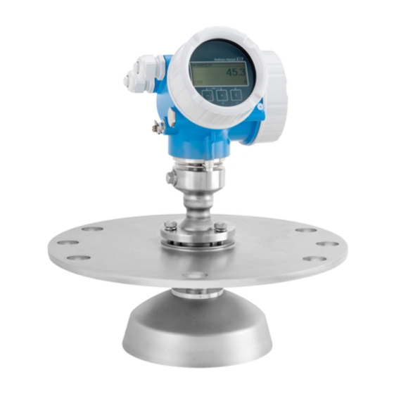
Micropilot FMR56, FMR57
Free space radar
Level measurement in bulk solids
Application
• Continuous, non-contact level measurement in powdery to granular bulk solids
• PP-cladded horn antenna (FMR56); horn or parabolic antenna (FMR57)
• Maximum measuring range: 70 m (230 ft)
• Process temperature: –40 to +400 °C (–40 to 752 °F)
• Process pressure: –1 to +16 bar (–14.5 to +232 psi)
• Accuracy: ± 3 mm
• International explosion protection certificates
• Linearity protocol (3-point, 5-point)
Your benefits
• Reliable measurement even for changing product and process conditions
• HistoROM data management for easy commissioning, maintenance and
diagnostics
• Highest reliability due to Multi-Echo Tracking
• SIL2 according to IEC 61508, SIL3 in case of homogeneous or heterogeneous
redundancy
• Seamless integration into control or asset management systems
• Intuitive user interface in national languages
• Bluetooth® wireless technology for commissioning, operation and maintenance via
free iOS / Android app SmartBlue
• Easy proof test for SIL
• Heartbeat Technology™
Solutions
Services
Advertisement
Table of Contents

Related Manuals for Endress+Hauser Micropilot FMR56


Summary of Contents for Endress+Hauser Micropilot FMR56
- Page 1 Solutions Services TI01042F/00/EN/10.20 71486058 2020-07-31 Technical Information Micropilot FMR56, FMR57 Free space radar Level measurement in bulk solids Application • Continuous, non-contact level measurement in powdery to granular bulk solids • PP-cladded horn antenna (FMR56); horn or parabolic antenna (FMR57) •...
- Page 2 Micropilot FMR56, FMR57 Table of contents Important document information ....4 Degree of protection ......
- Page 3 Micropilot FMR56, FMR57 Application packages ..... . . 89 Heartbeat Diagnostics ......
-
Page 4: Document Function
Micropilot FMR56, FMR57 Important document information Document function These Operating Instructions provide all of the information that is required in various phases of the life cycle of the device including: • Product identification • Incoming acceptance • Storage • Installation •... -
Page 5: Terms And Abbreviations
Document type "Safety Instructions" Nominal pressure FieldCare Scalable software tool for device configuration and integrated plant asset management solutions DeviceCare Universal configuration software for Endress+Hauser HART, PROFIBUS, FOUNDATION Fieldbus and Ethernet field devices Device Type Manager Device Description for HART communication protocol ε... -
Page 6: Registered Trademarks
Registered trademark of SCHNEIDER AUTOMATION, INC. Bluetooth® The Bluetooth® word mark and logos are registered trademarks owned by the Bluetooth SIG, Inc. and any use of such marks by Endress+Hauser is under license. Other trademarks and trade names are those of their respective owners. Apple®... -
Page 7: Measuring Principle
Micropilot FMR56, FMR57 Function and system design Measuring principle The Micropilot is a "downward-looking" measuring system, operating based on the time-of-flight method (ToF). It measures the distance from the reference point R (process connection of the measuring device) to the product surface. Radar pulses are emitted by an antenna, reflected off the product surface and received again by the radar system. -
Page 8: Operation
• Measurement is independent of product properties • Hardware and software developed according to SIL IEC 61508 Procurement • As the global market leader in level measurement, Endress+Hauser guarantees the security of your investment • Worldwide support and service Installation •... -
Page 9: Measuring Range
For very loose or loosened bulk solids, the lower group applies in each case. For dielectric constants (DC values) of many media commonly used in various industries refer • the Endress+Hauser DC manual (CP01076F) • the Endress+Hauser "DC Values App" (available for Android and iOS) Endress+Hauser... -
Page 10: Operating Frequency
Micropilot FMR56, FMR57 Operating frequency K-band (~ 26 GHz) As the transmission pulses are statistically coded, up to 8 Micropilot transmitters can be installed in the same tank. Transmission power Distance Mean power density in the direction of the beam 1 m (3.3 ft) - Page 11 Micropilot FMR56, FMR57 Output Output signal HART • Signal coding: FSK ±0.5 mA over current signal • Data transmission rate: 1 200 Bit/s • Galvanic isolation: Bluetooth® wireless technology • Device version: Order code 610 "Accessory mounted", option NF "Bluetooth"...
-
Page 12: Galvanic Isolation
Micropilot FMR56, FMR57 • Scan rate: Corresponds to the measuring cycle • Signal source / device variables: • Level linearized • Distance • Terminal voltage • Electronic temperature • Relative echo amplitude • Diagnostic values, advanced diagnostic blocks • Only for active interface measurement •... - Page 13 Micropilot FMR56, FMR57 HART device variables The measured values can be freely assigned to the device variables. Measured values for PV (primary variable) • Level linearized • Distance • Electronic temperature • Relative echo amplitude • Area of incoupling • Analog output adv. diagnostics 1 •...
- Page 14 Micropilot FMR56, FMR57 Input values Analog Output: • Analog value from PLC (for sensor block, external pressure to compensate for gas phase effects) • Analog value from PLC for transmission to display Digital Output: • Extended Diagnostic Block • Level Limiter •...
- Page 15 Contains parameters for backing up the device No output values Transducer Block configuration in the display module and for writing the saved configuration to the device. Access to these parameters is reserved for Endress+Hauser Service. Function blocks Block Contents Number of...
- Page 16 Micropilot FMR56, FMR57 Block Contents Number of Number of Execution Functionality permanent instantiatable time blocks blocks Multiple The Multiple Analog Output 20 ms Standard Analog Output Block is used to transmit analog Block values from the bus to the device.
-
Page 17: Terminal Assignment
Micropilot FMR56, FMR57 Power supply Terminal assignment Terminal assignment 2-wire: 4-20 mA HART A0036498 2 Terminal assignment 2-wire: 4-20 mA HART Without integrated overvoltage protection With integrated overvoltage protection Connection 4-20 mA HART passive: terminals 1 and 2, without integrated overvoltage protection... - Page 18 Micropilot FMR56, FMR57 Terminal assignment 2-wire: 4-20 mA HART, switch output A0036500 4 Terminal assignment 2-wire: 4-20 mA HART, switch output Without integrated overvoltage protection With integrated overvoltage protection Connection 4-20 mA HART passive: terminals 1 and 2, without integrated overvoltage protection...
- Page 19 Micropilot FMR56, FMR57 Terminal assignment 2-wire: 4-20 mA HART, 4-20 mA A0036500 6 Terminal assignment 2-wire: 4-20 mA HART, 4-20 mA Without integrated overvoltage protection With integrated overvoltage protection Connection current output 1, 4-20 mA HART passive: terminals 1 and 2, without integrated overvoltage...
- Page 20 Micropilot FMR56, FMR57 Terminal assignment 4-wire: 4-20 mA HART (10.4 to 48 V A0036516 8 Terminal assignment 4-wire: 4-20 mA HART (10.4 to 48 V Connection 4-20 mA HART (active): terminals 3 and 4 Connection supply voltage: terminals 1 and 2 Terminal for cable screen Block diagram 4-wire: 4-20 mA HART (10.4 to 48 V...
- Page 21 Micropilot FMR56, FMR57 Terminal assignment 4-wire: 4-20 mA HART (90 to 253 V A0036519 10 Terminal assignment 4-wire: 4-20 mA HART (90 to 253 V Connection 4-20 mA HART (active): terminals 3 and 4 Connection supply voltage: terminals 1 and 2...
- Page 22 Micropilot FMR56, FMR57 Block diagram 4-wire: 4-20 mA HART (90 to 253 V A0036527 11 Block diagram 4-wire: 4-20 mA HART (90 to 253 V Evaluation unit, e.g. PLC HART communication resistor (≥ 250 Ω); observe maximum load Connection for Commubox FXA195 or FieldXpert SFX350/SFX370 (via VIATOR Bluetooth modem) Analog display device;...
- Page 23 Micropilot FMR56, FMR57 Block diagram PROFIBUS PA / FOUNDATION Fieldbus A0036530 13 Block diagram PROFIBUS PA / FOUNDATION Fieldbus Cable screen; observe cable specifications Connection PROFIBUS PA / FOUNDATION Fieldbus Measuring device Switch output (open collector) Endress+Hauser...
- Page 24 Micropilot FMR56, FMR57 Connection examples for the switch output For HART devices, the switch output is available as an option. A0015909 14 Connection of a relay A0015910 15 Connection to a digital input Pull-up resistor Digital input For optimum interference immunity we recommend to connect an external resistor (internal resistance of the relay or pull-up resistor) of <...
- Page 25 Micropilot FMR56, FMR57 Device plugs In device versions with a device plug (M12 or 7/8"), it is not necessary to open the housing in order to connect the signal cable. A0011175 16 Pin assignment of M12 plug Signal + Not assigned Signal –...
- Page 26 Micropilot FMR56, FMR57 Supply voltage An external power supply is necessary. Various power supply units can be ordered from Endress+Hauser: see "Accessories" section 2-wire, 4-20mA HART, passive "Power supply, "Approval" Terminal voltage U Maximum load R, depending on the supply voltage U of the power supply unit output"...
- Page 27 Micropilot FMR56, FMR57 "Power supply, "Approval" Terminal voltage U at Maximum load R, depending on the supply voltage U of the power supply unit output" device 3) 4) C: 2-wire; 4-20mA 13 to 28 V R [ ] HART, 4-20mA...
-
Page 28: Current Consumption
Micropilot FMR56, FMR57 4-wire, 4-20mA HART, active "Power supply; output" Terminal voltage U Maximum load R K: 4-wire 90-253VAC; 4-20mA HART 90 to 253 V (50 to 60 Hz), overvoltage 500 Ω category II L: 4-wire 10.4-48VDC; 4-20mA HART 10.4 to 48 V... -
Page 29: Potential Equalization
Micropilot FMR56, FMR57 FOUNDATION Fieldbus Device basic current 15 mA Failure current FDE (Fault 0 mA Disconnection Electronic) FISCO 17.5 V 550 mA 5.5 W 5 nF 10 μH Power supply failure • Configuration is retained in the HistoROM (EEPROM). -
Page 30: Overvoltage Protection
400 to 700 V Threshold impulse voltage < 800 V Capacitance at 1 MHz < 1.5 pF Nominal arrest impulse voltage (8/20 μs) 10 kA External overvoltage protection module HAW562 or HAW569 from Endress+Hauser are suited as external overvoltage protection. Endress+Hauser... -
Page 31: Performance Characteristics
Micropilot FMR56, FMR57 Performance characteristics Reference operating • Temperature = +24 °C (+75 °F) ±5 °C (±9 °F) conditions • Pressure = 960 mbar abs. (14 psia) ±100 mbar (±1.45 psi) • Humidity = 60 % ±15 % • Reflector: metal plate with a diameter ≥ 1 m (40 in) •... -
Page 32: Influence Of Ambient Temperature
Micropilot FMR56, FMR57 Response time The response time can be configured. The following step response times (in accordance with DIN EN IEC 61298-2 / DIN EN IEC 60770-1) are when damping is switched off: Tank height Sampling rate Response time <... -
Page 33: Installation
Micropilot FMR56, FMR57 Installation Installation conditions Orientation A0016883 • Recommended distance A wall - nozzle outer edge: ~ 1/6 of the vessel diameter. However, the device must not under any circumstances be mounted closer than 20 cm (7.87 in) to the vessel wall. - Page 34 Micropilot FMR56, FMR57 Internal vessel fittings A0018946 Avoid the location of internal fittings (limit switches, temperature sensors, struts etc.) inside the signal beam. Take the beam angle into account. Endress+Hauser...
- Page 35 Micropilot FMR56, FMR57 Avoiding interference echoes A0016889 Metal orifice plates, installed at an angle to scatter the radar signals, help prevent interference echoes Measurement in a plastic vessel If the outer wall of the vessel is made of a non-conductive material (e.g. GFRP) microwaves can also be reflected off interfering installations outside of the vessel (e.g.
-
Page 36: Optimization Options
Micropilot FMR56, FMR57 A0017123 Optimization options • Antenna size The larger the antenna the smaller the beam angle α, resulting in fewer interference echoes. • Interference echo suppression (mapping) Measurement can be optimized by electronically suppressing interference echoes • Take into account the orientation of the antenna, the marking on the flange or threaded connection •... - Page 37 DC Manual (CP00019F) and in Endress+Hauser' s "DC Values App" (available for Android and iOS). • In principle it is possible to measure up to the tip of the antenna with the Micropilot. However, due...
- Page 38 Micropilot FMR56, FMR57 • Align the antenna so that it is perpendicular to the product surface. Optionally, an adjustable flange seal (accessory) can be used for alignment • A marking is provided on the gland to aid the alignment. This marking must be aligned towards the tank wall as much as possible.
- Page 39 Micropilot FMR56, FMR57 Horn antenna with mounting bracket (FMR56) A0016865 21 Mounting the horn antenna with a mounting bracket Using the mounting bracket, position the antenna so that it is perpendicular to the product surface. NOTICE There is no conductive connection between the mounting bracket and transmitter housing.
- Page 40 Micropilot FMR56, FMR57 A0016825 22 Nozzle height for horn antenna (FMR57) Antenna Maximum nozzle height H (valid for antennas without an antenna extension) Horn 80mm/3" 260 mm (10.2 in) Horn 100mm/4" 480 mm (18.9 in) Please contact the manufacturer' s support service for applications with nozzles that are higher than indicated in the table.
- Page 41 Micropilot FMR56, FMR57 øD A0016827 23 Nozzle mounting of Micropilot FMR57 with parabolic antenna Antenna completely projects out of the nozzle Antenna completely inside the nozzle Antenna Antenna diameter D Nozzle height H for Case 1 Maximum nozzle height H...
- Page 42 Micropilot FMR56, FMR57 Installation with hinged flange The length of the antenna must be taken into account in the case of hinged flanges. A0018878 Dismantling the parabolic reflector The parabolic reflector can be dismantled for installation in a nozzle: A0018877 Parabolic reflector 4 screws;...
- Page 43 Micropilot FMR56, FMR57 A0016931 24 Micropilot FMR57 with alignment unit Integrated purge air connection for FMR57 In applications with strong dust emissions, the integrated purge air connection can prevent the antenna from becoming clogged. Pulse operation is recommended. A0016932 ...
-
Page 44: Container With Heat Insulation
Micropilot FMR56, FMR57 Container with heat insulation A0032207 If process temperatures are high, the device should be included in the usual container insulation system (2) to prevent the electronics from heating as a result of thermal radiation or convection. The insulation should not be higher than the neck of the device (1). -
Page 45: Temperature Range
Micropilot FMR56, FMR57 Environment Temperature range Measuring device –40 to +80 °C (–40 to +176 °F); –50 °C (–58 °F) with manufacturer declaration on request Local display –20 to +70 °C (–4 to +158 °F), the readability of the display may be impaired at temperatures outside the temperature range. - Page 46 Micropilot FMR56, FMR57 FMR56 GT19 housing (plastic PBT) Temperature specifications: °C (°F) A0019351 Power supply; output (item 2 in the product structure) E, G Switch output not used (-40) (174) (174) (174) (176) (174) (176) (-40) (-40) (-40) E, G...
- Page 47 Micropilot FMR56, FMR57 FMR57 Seal: Viton GLT Housing GT18 (316 L) Temperature specifications: °C (°F) A0019351 Power supply; output (item 2 in the product structure) Switch output used (-40) (171) (171) (171) (392) (144) (392) (-40) (-40) (-40) Channel 2 not used...
- Page 48 Micropilot FMR56, FMR57 FMR57 Seal: Viton GLT Housing GT20 (aluminum coated) Temperature specifications: °C (°F) A0019351 Power supply; output (item 2 in the product structure) (-40) (178) (178) (178) (392) (158) (392) (-40) (-40) (-40) Switch output not used (-40)
-
Page 49: Storage Temperature
Micropilot FMR56, FMR57 FMR57 Seal: graphite GT19 housing (plastic PBT) Temperature specifications: °C (°F) A0019351 Power supply; output (item 2 in the product structure) (-40) (176) (176) (176) (752) (59) (752) (-40) (-40) (-40) Switch output not used (-40) (169) -
Page 50: Vibration Resistance
Micropilot FMR56, FMR57 Altitude according to • Generally up to 2 000 m (6 600 ft) above MSL. • Above 2 000 m (6 600 ft) if the following conditions are met: IEC61010-1 Ed.3 • Ordering feature 020 "Power supply; Output" = A, B, C, E or G (2-wire versions) •... -
Page 51: Process Temperature, Process Pressure
Micropilot FMR56, FMR57 Process Process temperature, process The pressure ranges indicated can be reduced by the choice of process connection. The nominal pressure pressure (PN) indicated on the nameplate refers to a reference temperature of 20 °C, and of 100 °F for ASME flanges. Observe pressure-temperature dependency. - Page 52 Micropilot FMR56, FMR57 Feature 090 "Seal" Process temperature range Process pressure range A6: Viton GLT –40 to +200 °C (–40 to +392 °F) = –1 to 16 bar (–14.5 to 232 psi) D4: graphite –40 to +400 °C (–40 to +752 °F)
-
Page 53: Mechanical Construction
Micropilot FMR56, FMR57 Mechanical construction Dimensions Dimensions of the electronics housing 98 (3.86)* 78 (3.07) 90 (3.54) A0011666 28 Housing GT18 (316L). Unit of measurement mm (in) *For devices with integrated overvoltage protection. 99 (3.9)* 78 (3.07) 90 (3.54) A0011346 ... - Page 54 Micropilot FMR56, FMR57 FMR56 with mounting bracket or onsite mounting device øc ød A0017747 31 Dimensions of FMR56 without process connection. Unit of measurement mm (in) Reference point of measurement Antenna Øc Ød Horn 80mm/3" 137.9 mm (5.43 in) 15 mm (0.59 in)
- Page 55 Micropilot FMR56, FMR57 FMR56 with slip-on flange 3"/DN80 ø21 (0.83) ø75 (2.95) ø116 (4.57) ø157 (6.18) ø200 (7.87) A0023377 33 Dimensions of FMR56 with slip-on flange 3"/DN80. Unit of measurement mm (in) Reference point of measurement Applies to the following device versions •...
- Page 56 Micropilot FMR56, FMR57 FMR56 with slip-on flange 4"/DN100 ø143 (5.63) ø95 (3.74) ø175 (6.89) ø135.6 (5.34) ø190.5 (5.7) ø175 (6.89) ø228.6 (9) ø190.5 (7.5) ø228.6 (9) A0023379 34 Dimensions of FMR56 with slip-on flange 4"/DN100. Unit of measurement mm (in) Horn antenna 100mm/4"...
- Page 57 Micropilot FMR56, FMR57 FMR56 with slip-on flange 6"/DN150 ø163 (6.42) ø143 (5.63) 24 (0.94) ø240 (9.45) ø240.7 (9.48) ø241.3 (9.5) ø285 (11.2) ø285 (11.2) A0023380 35 Dimensions of FMR56 with slip-on flange 6"/DN150. Unit of measurement mm (in) Horn antenna 100mm/4"...
- Page 58 Micropilot FMR56, FMR57 FMR57 with horn antenna - standard version ø40 (1.57) ø40 (1.57) ød ød øD øD øD A0023392 36 Dimensions of FMR57 with horn antenna - standard version. Unit of measurement mm (in) Process connection: alignment unit with UNI flange...
- Page 59 Micropilot FMR56, FMR57 FMR57 with horn antenna - high-temperature version ø40 (1.57) ø40 (1.57) ød ød øD øD A0023394 37 Dimensions of FMR57 with horn antenna - high-temperature version; engineering unit: mm(in) Process connection: alignment unit with UNI flange...
- Page 60 Micropilot FMR56, FMR57 FMR57 with parabolic antenna øF øF øD øD øD A0023393 38 Dimensions of FMR57 with parabolic antenna, engineering unit: mm (in) Process connection: alignment unit with UNI flange Process connection: UNI flange Process connection: flange Reference point of measurement ØD As per flange standard ASME B16.5 / EN1092-1 / JIS B2220...
- Page 61 Micropilot FMR56, FMR57 FMR57: dimensions of flanges Process connection - flange Dimensions ØD and b as per flange standard: • EN1092-1 (suitable for DIN2527) • ASME B16.5 • JIS B2220 UNI flange for FMR57 ø26 (1.02) ø19 (0.75) ø26 (1.02) ø23 (0.91)
- Page 62 Micropilot FMR56, FMR57 Alignment unit with UNI flange for FMR57 ø85(3.35) mm(in) A0018948 Viton seal UNI flange for FMR57 Clamping screw 3 x M8, offset by 120° In the high-temperature version of the FMR57 (feature 090: "Seal", version D4: "Graphite, -40 to 400°C"), there is no Viton seal (1) on the alignment unit.
- Page 63 Micropilot FMR56, FMR57 Materials: Housing GT18 (stainless steel, corrosion- resistant) A0036037 No. Component part Material Housing CF3M similar to 316L/1.4404 2.1 Electronics compartment cover • Cover: CF3M (similar to 316L/ 1.4404) • Window: glass • Cover seal: NBR • Window seal: NBR •...
-
Page 64: Materials: Gt19 Housing (Plastic)
Micropilot FMR56, FMR57 Materials: GT19 housing (plastic) A0013788 No. Component part Material Housing 2.1 Electronics compartment cover • Sight glass: PC • Rim: PBT-PC • Cover seal: EPDM • Thread coating: graphite-based lubricant varnish 2.2 Connection compartment cover • Cover: PBT •... -
Page 65: Materials: Gt20 Housing (Die-Cast Aluminum, Powder- Coated)
Micropilot FMR56, FMR57 Materials: GT20 housing (die-cast aluminum, powder- coated) A0036037 No. Component part Material Housing, RAL 5012 (blue) • Housing: AlSi10Mg(<0.1% Cu) • Coating: polyester 2.1 Electronics compartment cover, RAL 7035 (gray) • Cover: AlSi10Mg(<0.1% Cu) • Window: glass •... - Page 66 Micropilot FMR56, FMR57 No. Component part Material Ground terminal • Screw: A2 • Spring washer: A2 • Clamp: 304 (1.4301) • Bracket: 304 (1.4301) Adhesive nameplate Plastic In the version with the M12 plug, the seal material is Viton (different from standard).
- Page 67 Micropilot FMR56, FMR57 FMR57 A0018958 Horn standard version with alignment unit and UNI flange Horn standard version with UNI flange Horn standard version with standard flange Horn standard version with threaded adapter Parabolic version with alignment unit and UNI flange...
- Page 68 Micropilot FMR56, FMR57 Item Component part Material Clamping flange 316L (1.4404) Seal (except for version "G") Housing adapter 316L (1.4404) Plug 316L (1.4404) Adapter (G→NPT) 316L (1.4404) Seal PTFE (tape) Process connection 316L (1.4404) Parabolic mirror 316L (1.4404) Screws Feed...
-
Page 69: Materials: Weather Protection Cover
Micropilot FMR56, FMR57 Materials: Weather protection cover A0015473 Component: Material Protection cover: 316L (1.4404) Rubber molded part (4x): EPDM Tensioning screw: 316L (1.4404) + carbon thread Holder: 316L (1.4404) Ground terminal • Screw: A4 • Spring washer: A4 • Clamp: 316L (1.4404) •... - Page 70 Micropilot FMR56, FMR57 Operability Operating concept Operator-oriented menu structure for user-specific tasks • Commissioning • Operation • Diagnostics • Expert level Operating languages • English • Deutsch • Français • Español • Italiano • Nederlands • Portuguesa • Polski • русский язык (Russian) •...
- Page 71 Micropilot FMR56, FMR57 Local operation Operation Pushbuttons Touch Control with Order code for Option C "SD02" Option E "SD03" "Display; Operation" A0036312 A0036313 Display 4-line display 4-line display elements white background lighting; switches to red in event of device error Format for displaying measured variables and status variables can be individually configured Permitted ambient temperature for the display: –20 to +70 °C (–4 to +158 °F)
- Page 72 Micropilot FMR56, FMR57 Operation via Bluetooth® Requirements wireless technology A0036790 40 Device with Bluetooth module Electronics housing of the device Bluetooth module This operation option is only available for devices with Bluetooth module. There are the following options: • The device has been ordered with a Bluetooth module: Feature 610 "Accessory Mounted", option NF "Bluetooth"...
- Page 73 Micropilot FMR56, FMR57 Remote operation Via HART protocol A0036169 42 Options for remote operation via HART protocol PLC (Programmable Logic Controller) Transmitter power supply unit, e.g. RN221N (with communication resistor) Connection for Commubox FXA191, FXA195 and Field Communicator 375, 475 Field Communicator 475 Computer with operating tool (e.g.
- Page 74 Micropilot FMR56, FMR57 Via FOUNDATION Fieldbus FF-HSE FF-H1 FF-H1 A0017188 44 FOUNDATION Fieldbus system architecture with associated components FFblue Bluetooth modem Field Xpert SFX350/SFX370 DeviceCare/FieldCare NI-FF interface card Industrial network FF-HSE High Speed Ethernet FF-H1 FOUNDATION Fieldbus-H1 Linking Device FF-HSE/FF-H1...
- Page 75 Micropilot FMR56, FMR57 DeviceCare/FieldCare via service interface (CDI) A0032466 45 DeviceCare/FieldCare via service interface (CDI) Service interface (CDI) of the instrument (= Endress+Hauser Common Data Interface) Commubox FXA291 Computer with DeviceCare/FieldCare operating tool Endress+Hauser...
- Page 76 Micropilot FMR56, FMR57 SupplyCare inventory SupplyCare is a web-based operating program for coordinating the flow of material and information along the supply chain. SupplyCare provides a comprehensive overview of the levels of management software geographically distributed tanks and silos, for instance, providing complete transparency over the current inventory situation, regardless of time and location.
- Page 77 Micropilot FMR56, FMR57 A0034288 46 Example of inventory management platform with SupplyCare Enterprise SCE30B SupplyCare Enterprise (via Web browser) SupplyCare Enterprise installation SupplyCare Enterprise on mobile devices (via Web browser) Ethernet/WLAN/UMTS Fieldgate FXA42 Power supply 24 V DC Modbus TCP via Ethernet as server/client...
- Page 78 Micropilot FMR56, FMR57 Cloud-based application: SupplyCare Hosting SupplyCare Hosting is offered as a hosting service (software as a service). Here, the software is installed within the Endress+Hauser IT infrastructure and made available to the user in the Endress +Hauser portal. A0034289 ...
-
Page 79: Certificates And Approvals
CE mark in the corresponding EU Declaration of Conformity along with the standards applied. Endress+Hauser confirms successful testing of the device by affixing to it the CE mark. The measuring system complies with the substance restrictions of the Restriction on Hazardous RoHS Substances Directive 2011/65/EU (RoHS 2). -
Page 80: Marine Approval
See order code for 590 "Additional approval" Radio standard EN 302729 The Micropilot FMR56 and FMR57 devices comply with the LPR (Level Probing Radar) radio standard EN 302729. The devices are approved for unrestricted use inside and outside of closed vessels in countries of the EU and EFTA. - Page 81 Micropilot FMR56, FMR57 Country Name of the station Latitude Longitude Robledo 40°25' 3 8" North 04°14' 5 7" West Hungary Penc 47°47' 2 2" North 19°16' 5 3" East As a general rule, the requirements outlined in EN 302729 must be observed.
- Page 82 Micropilot FMR56, FMR57 Feature 100 in the product structure Process connection UNI slip-on flange 4"/DN100/100, PP UNI slip-on flange 6"/DN150/150, PP • Process connections that do not have CRN approval are not listed in this table. • Please refer to the product structure to discover which process connections are available for a specific device type.
-
Page 83: Hard-Copy Product Documentation
Micropilot FMR56, FMR57 Test, certificate Feature 580 "Test, Designation certificate" 3.1 Material certificate, pressurized parts, EN10204-3.1 inspection certificate Declaration of Conformity ASME B31.3: The construction, the material used, the pressure and temperature ranges and the labeling of the devices meet the requirements of ASME B31.3... - Page 84 Micropilot FMR56, FMR57 Other standards and • EN 60529 Degrees of protection provided by enclosures (IP code) guidelines • EN 61010-1 Safety Requirements for Electrical Equipment for Measurement, Control and Laboratory Use • IEC/EN 61326 "Emission in accordance with Class A requirements". Electromagnetic compatibility (EMC requirements).
-
Page 85: Ordering Information
• Depending on the device: Direct input of measuring point-specific information such as measuring range or operating language • Automatic verification of exclusion criteria • Automatic creation of the order code and its breakdown in PDF or Excel output format • Ability to order directly in the Endress+Hauser Online Shop Endress+Hauser... - Page 86 Micropilot FMR56, FMR57 3-point linearity protocol The following points must be considered if option F3 (3-point linearity protocol) was selected in feature 550 ("Calibration"). The 3 points of the linearity protocol are defined as follows: A0023272 48 Points of the 3-point linearity protocol; engineering unit: mm (in)
- Page 87 Micropilot FMR56, FMR57 5-point linearity protocol The following points must be considered if option F4 (5-point linearity protocol) was selected in feature 550 ("Calibration"). The 5 points of the linearity protocol are evenly distributed over the measuring range (0% - 100%).
-
Page 88: Customer-Specific Configuration
Micropilot FMR56, FMR57 Customer-specific If the option IJ: "Customized parameterization HART", IK "Customized parameterization PA" or IL "Customized parameterization FF" has been selected in feature 570 "Service", presettings that differ configuration from the default settings can be selected for the following parameters:... -
Page 89: Application Packages
Micropilot FMR56, FMR57 Application packages Heartbeat Diagnostics Availability Available in all device versions. Function • Continuous self-monitoring of the device. • Diagnostic messages output to • the local display. • an asset management system (e.g. FieldCare/DeviceCare). • an automation system (e.g. PLC). -
Page 90: Heartbeat Verification
Micropilot FMR56, FMR57 Heartbeat Verification Availability Available for the following versions of feature 540 "Application package": • EH: Heartbeat Verification + Monitoring • EJ: Heartbeat Verification Device functionality checked on demand • Verification of the correct functioning of the measuring device within specifications. - Page 91 Micropilot FMR56, FMR57 Heartbeat Monitoring Availability Available for the following versions of feature 540 "Application package": EH: Heartbeat Verification + Monitoring Function • In addition to the verification parameters, the corresponding parameter values are also logged. • Existing measured variables, such as the echo amplitude, are used in the Foam detection and Build-up detection wizards.
- Page 92 Micropilot FMR56, FMR57 Accessories Device-specific accessories Weather protection cover Accessory Description Weather protection cover A0015466 300 (11.8) 275 (10.8) 255.1 (10) 164 (6.46) A0015472 49 Weather protection cover; Dimensions: mm (in) The weather protection cover can be ordered together with the device (product structure, feature 620 "Accessory Enclosed", option PB "Weather Protection Cover").
- Page 93 Micropilot FMR56, FMR57 Adjustable flange seal for FMR50/FMR56 Accessories Description Adjustable flange seal for FMR50/FMR56 ød øD A0018871 UNI slip-on flange Adjustable flange seal Nozzle The material properties and process conditions of the adjustable flange seal must be compatible with the properties (temperature, pressure, resistance) of the process.
- Page 94 Micropilot FMR56, FMR57 Accessories Description Technical data: version ASME/JIS Order number 71249070 71249072 71249073 Compatible with • ASME 3" 150lbs ASME 4" 150lbs ASME 6" 150lbs • JIS 80A 10K Recommended screw length 100 mm (3.9 in) 100 mm (3.9 in) 110 mm (4.3 in)
- Page 95 Micropilot FMR56, FMR57 Remote display FHX50 Accessories Description Remote display FHX50 A0019128 • Material: • Plastic PBT • 316L/1.4404 • Aluminum • Degree of protection: IP68 / NEMA 6P and IP66 / NEMA 4x • Suitable for display modules: • SD02 (push buttons) •...
- Page 96 Micropilot FMR56, FMR57 Horn protection for horn antenna Accessories Description Horn protection for horn antenna 80 mm (3 in) or 100 mm (4 in) ød øD A0019143 Horn antenna of the Micropilot (not included in the delivery of the horn protection) Horn protection ⌀d Diameter of horn protection (see table below)
- Page 97 Micropilot FMR56, FMR57 Overvoltage protection Accessory Description Overvoltage protection for 2-wire-devices OVP10 (1 channel) OVP20 (2 channel) A0021734 Technical data • Resistance per channel: 2 * 0.5 Ω • Threshold DC voltage: 400 to 700 V • Threshold impulse voltage: < 800 V •...
- Page 98 Micropilot FMR56, FMR57 Bluetooth module for HART devices Accessory Description Bluetooth module A0036493 • Quick and easy commissioning via SmartBlue (app) • No additional tools or adapters required • Signal curve via SmartBlue (app) • Encrypted single point-to-point data transmission (tested by Fraunhofer institue) and password protected communication via Bluetooth®...
-
Page 99: Communication-Specific Accessories
For details, see "Technical Information" TI00404F Commubox FXA291 Connects Endress+Hauser field devices with a CDI interface (= Endress+Hauser Common Data Interface) and the USB port of a computer or laptop Order number: 51516983 For details, see "Technical Information" TI00405C... -
Page 100: Supplementary Documentation
For an overview of the scope of the associated Technical Documentation, refer to the following: • W@M Device Viewer (www.endress.com/deviceviewer): Enter the serial number from nameplate • Endress+Hauser Operations App: Enter the serial number from the nameplate or scan the 2D matrix code (QR code) on the nameplate Brief Operating Instructions... - Page 102 *71486058* 71486058 www.addresses.endress.com...