Endress+Hauser Micropilot FMR56 Brief Operating Instructions
Free space radar
Hide thumbs
Also See for Micropilot FMR56:
- Operating instructions manual (198 pages) ,
- Technical information (103 pages) ,
- Brief operating instructions (72 pages)
Table of Contents
Advertisement
Quick Links
KA01127F/00/EN/02.18
71396518
2018-04-12
Products
Brief Operating Instructions
Micropilot FMR56, FMR57
FOUNDATION Fieldbus
Free space radar
These Instructions are Brief Operating Instructions; they are
not a substitute for the Operating Instructions pertaining to
the device.
Detailed information about the device can be found in the
Operating Instructions and the other documentation:
Available for all device versions via:
– Internet:
www.endress.com/deviceviewer
– Smart phone/tablet: Endress+Hauser Operations App
Solutions
Services
Advertisement
Table of Contents

Related Manuals for Endress+Hauser Micropilot FMR56


Summary of Contents for Endress+Hauser Micropilot FMR56
- Page 1 Operating Instructions pertaining to the device. Detailed information about the device can be found in the Operating Instructions and the other documentation: Available for all device versions via: – Internet: www.endress.com/deviceviewer – Smart phone/tablet: Endress+Hauser Operations App...
- Page 2 Micropilot FMR56, FMR57 FOUNDATION Fieldbus Order code: XXXXX-XXXXXX Ser. no.: XXXXXXXXXXXX Ext. ord. cd.: XXX.XXXX.XX Serial number www.endress.com/deviceviewer Endress+Hauser Operations App A0023555 Endress+Hauser...
-
Page 3: Table Of Contents
Micropilot FMR56, FMR57 FOUNDATION Fieldbus Table of contents Table of contents Wichtige Hinweise zum Dokument ..........4 Symbols . -
Page 4: Wichtige Hinweise Zum Dokument
Wichtige Hinweise zum Dokument Micropilot FMR56, FMR57 FOUNDATION Fieldbus 11.2 Scaling of the measured value in an AI Block ..........60 11.3 Language selection . - Page 5 Micropilot FMR56, FMR57 FOUNDATION Fieldbus Wichtige Hinweise zum Dokument 1.1.3 Tool symbols A0011222 A0011220 A0011219 A0013442 A0011221 Cross-head Flat blade Torx screwdriver Allen key Hexagon wrench screwdriver screwdriver 1.1.4 Symbols for certain types of information Symbol Meaning Symbol Meaning Permitted...
- Page 6 Wichtige Hinweise zum Dokument Micropilot FMR56, FMR57 FOUNDATION Fieldbus 1.1.6 Symbols at the device Symbol Meaning Safety instructions Observe the safety instructions contained in the associated Operating Instructions. Temperature resistance of the connection cables Specifies the minimum value of the temperature resistance of the connection cables.
-
Page 7: Terms And Abbreviations
Time of Flight FieldCare Scalable software tool for device configuration and integrated plant asset management solutions DeviceCare Universal configuration software for Endress+Hauser HART, PROFIBUS, FOUNDATION Fieldbus and Ethernet field devices Device Type Manager Device Description for HART communication protocol ε... -
Page 8: Registered Trademarks
Registered trademark of the FieldComm Group, Austin, Texas, USA Bluetooth® The Bluetooth® word mark and logos are registered trademarks owned by the Bluetooth SIG, Inc. and any use of such marks by Endress+Hauser is under license. Other trademarks and trade names are those of their respective owners. Apple®... -
Page 9: Basic Safety Instructions
The manufacturer is not liable for damage caused by improper or non-designated use. Verification for borderline cases: ‣ For special measured materials and cleaning agents, Endress+Hauser is glad to provide assistance in verifying the corrosion resistance of wetted materials, but does not accept any warranty or liability. -
Page 10: Workplace Safety
The measuring system meets the legal requirements of the applicable EC guidelines. These are listed in the corresponding EC Declaration of Conformity together with the standards applied. Endress+Hauser confirms successful testing of the device by affixing to it the CE mark. Endress+Hauser... - Page 11 The measuring system meets the legal requirements of the applicable EAC guidelines. These are listed in the corresponding EAC Declaration of Conformity together with the standards applied. Endress+Hauser confirms successful testing of the device by affixing to it the EAC mark. Endress+Hauser...
-
Page 12: Product Description
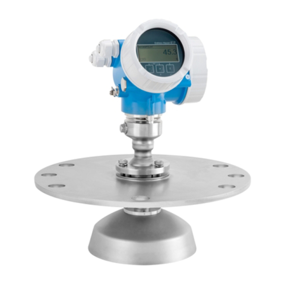
Product description Micropilot FMR56, FMR57 FOUNDATION Fieldbus Product description Product design 3.1.1 Micropilot FMR56 A0016791 1 Design of the Micropilot FMR56 (26 GHz) Electronics housing Horn 80mm/100 mm (3in/4in), PP cladded Flange Mounting bracket Endress+Hauser... -
Page 13: Incoming Acceptance And Product Identification
• Do the nameplate data match the ordering information on the delivery note? • Is the DVD with the operating tool present? If required (see nameplate): Are the Safety Instructions (XA) present? If one of these conditions is not satisfied, contact your Endress+Hauser Sales Center. Endress+Hauser... -
Page 14: Product Identification
): All information about the measuring device is displayed. • Enter the serial number from the nameplates into the Endress+Hauser Operations App or scan the 2-D matrix code (QR code) on the nameplate with the Endress+Hauser Operations App: all the information for the measuring device is displayed. -
Page 15: Storage, Transport
Micropilot FMR56, FMR57 FOUNDATION Fieldbus Storage, Transport Storage, Transport Storage conditions • Permitted storage temperature: –40 to +80 °C (–40 to +176 °F) • Use the original packaging. Transport product to the measuring point NOTICE Housing or antenna horn may be damaged or break away. -
Page 16: Installation
Installation Micropilot FMR56, FMR57 FOUNDATION Fieldbus Installation Installation conditions 6.1.1 Mounting position • Recommended distance A from wall to outer edge of nozzle: ~ 1/6 of vessel diameter. Nevertheless the device should not be installed closer than 20 cm (7.87 in) to the vessel wall. - Page 17 Micropilot FMR56, FMR57 FOUNDATION Fieldbus Installation 6.1.2 Vessel installations Avoid any installations (limit switches, temperature sensors, braces etc.) inside the signal beam. Take into account the beam angle . A0018946 Endress+Hauser...
- Page 18 If the outer wall of the vessel is made of a non-conductive material (e.g. GRP), microwaves can also be reflected off interfering installations outside the vessel (e.g. metallic pipes (1), ladders (2), grates (3), ...). Therefore, there should be no such interfering installations in the signal beam. Please contact Endress+Hauser for further information. Endress+Hauser...
- Page 19 Micropilot FMR56, FMR57 FOUNDATION Fieldbus Installation A0017125 6.1.5 Optimization options • Antenna size The bigger the antenna, the smaller the beam angle α and the fewer interference echoes → 20. • Mapping The measurement can be optimized by means of electronic suppression of interference echoes.
- Page 20 Installation Micropilot FMR56, FMR57 FOUNDATION Fieldbus • Metallic screens mounted at a slope They spread the radar signals and can, therefore, reduce interference echoes. • Variable flange seal (FMR56) Using the variable flange seal, the device can be aligned in the direction of the product surface.
- Page 21 Micropilot FMR56, FMR57 FOUNDATION Fieldbus Installation Beam diameter W as a function of beam angle α and measuring distance D: FMR56 Antenna size 80 mm (3 in) 100 mm (4 in) Beam angle α 10° 8° Measuring distance (D) Beamwidth diameter (W) 3 m (9.8 ft)
-
Page 22: Measuring Conditions
(high DC value, flat angle of repose) are met, shorter distances can be achieved. Dielectric constants of important media commonly used in various industries are summarized in the DC manual (CP01076F) and in the Endress+Hauser "DC Values App" (available for Android and iOS). Endress+Hauser... -
Page 23: Installation In Vessel (Free Space)
Micropilot FMR56, FMR57 FOUNDATION Fieldbus Installation 100% A0016916 Device A [mm (in)] C [mm (in)] FMR56 400(15.7) 50 to 150(1.97 to 5.91) FMR57 Installation in vessel (free space) 6.3.1 Horn antenna with slip-on flange (FMR56) Alignment When using the Micropilot with a slip-on flange in explosion-hazardous areas, strictly observe all specifications in the relevant Safety Instructions (XA). - Page 24 Installation Micropilot FMR56, FMR57 FOUNDATION Fieldbus ° ° ° A0019434 Depending on the device version the marking may be a circle or two short parallel lines. Nozzle mounting øD A0016868 5 Nozzle height and diameter for horn antenna with slip-on flange...
- Page 25 Micropilot FMR56, FMR57 FOUNDATION Fieldbus Installation 6.3.2 Horn antenna with mounting bracket (FMR56) A0016865 6 Installation of the horn antenna with mounting bracket Align the antenna vertically to the product surface using the mounting bracket. NOTICE The mounting bracket has no conductive connection to the transmitter housing.
- Page 26 Installation Micropilot FMR56, FMR57 FOUNDATION Fieldbus ° ° ° A0019434 Depending on the device version the marking may be a circle or two short parallel lines. Nozzle mounting The horn antenna should protrude from the nozzle. If this is not possible for mechanical reasons, larger nozzle heights can be accepted.
- Page 27 480 mm (18.9 in) Feature 070 of the product structure valid for antennas without antenna extension Please contact Endress+Hauser for applications with higher nozzle. Threaded connection For devices with a threaded connection it may be necessary - depending on the antenna size - to unmount the horn before fastening the device and to mount it again afterwards.
- Page 28 Installation Micropilot FMR56, FMR57 FOUNDATION Fieldbus øD A0016827 8 Nozzle mounting of Micropilot FMR57 with parabolic antenna Antenna protrudes from the nozzle Antenna completely within the nozzle Antenna Antenna diameter D Nozzle height H for case 1 Maximum nozzle height H for case FA: Parabol 200mm/8"...
- Page 29 Micropilot FMR56, FMR57 FOUNDATION Fieldbus Installation Standard installation øD A0018874 Nozzle Antenna size D 200 mm (8 in) 173 mm (6.81 in) < 50 mm (1.96 in) 250 mm (10 in) 236 mm (9.29 in) < 50 mm (1.96 in)
- Page 30 Installation Micropilot FMR56, FMR57 FOUNDATION Fieldbus A0018878 6.3.5 Alignment device for FMR57 Using the alignment device it is possible to tilt the antenna axis by up to 15° in all directions. The alignment device is used for the optimum alignment of the radar beam with the bulk solids surface.
- Page 31 Micropilot FMR56, FMR57 FOUNDATION Fieldbus Installation Align antenna axis: Loosen screws. Align antenna axis (up to. ± 15° in all directions). Tighten screws with 15 Nm (11 lbf ft). 6.3.6 Integrated air purge connection for FMR57 In extremely dusty applications, the integrated air purge connection can prevent clogging of the antenna.
-
Page 32: Container With Heat Insulation
Installation Micropilot FMR56, FMR57 FOUNDATION Fieldbus Container with heat insulation A0032207 If process temperatures are high, the device should be included in the usual container insulation system (2) to prevent the electronics from heating as a result of thermal radiation or convection. -
Page 33: Turning The Display
Micropilot FMR56, FMR57 FOUNDATION Fieldbus Installation Turning the display 6.6.1 Opening cover 3 mm A0021430 Loosen the screw of the securing clamp of the electronics compartment cover using an Allen key (3 mm) and turn the clamp 90 ° counterclockwise. -
Page 34: Post-Installation Check
Installation Micropilot FMR56, FMR57 FOUNDATION Fieldbus 6.6.3 Closing electronics compartment cover 3 mm 2,5 Nm A0021451 Screw back firmly electronics compartment cover. Turning securing clamp 90 ° clockwise and tighten the clamp with 2.5 Nm using the Allen key (3 mm). -
Page 35: Electrical Connection
Micropilot FMR56, FMR57 FOUNDATION Fieldbus Electrical connection Electrical connection Connection conditions 7.1.1 Terminal assignment Terminal assignment 4-wire: 4-20 mA HART (90 to 253 V A0036519 11 Terminal assignment 4-wire: 4-20 mA HART (90 to 253 V Connection 4-20 mA HART (active): terminals 3 and 4... - Page 36 Electrical connection Micropilot FMR56, FMR57 FOUNDATION Fieldbus CAUTION To ensure electrical safety: ‣ Do not disconnect the protective connection. ‣ Disconnect the supply voltage before disconnecting the protective earth. Connect protective earth to the internal ground terminal (3) before connecting the supply voltage.
- Page 37 Micropilot FMR56, FMR57 FOUNDATION Fieldbus Electrical connection Terminal assignment PROFIBUS PA / FOUNDATION Fieldbus A0036500 12 Terminal assignment PROFIBUS PA / FOUNDATION Fieldbus Without integrated overvoltage protection With integrated overvoltage protection Connection PROFIBUS PA / FOUNDATION Fieldbus: terminals 1 and 2, without integrated overvoltage...
- Page 38 Electrical connection Micropilot FMR56, FMR57 FOUNDATION Fieldbus Block diagram PROFIBUS PA / FOUNDATION Fieldbus A0036530 13 Block diagram PROFIBUS PA / FOUNDATION Fieldbus Cable screen; observe cable specifications Connection PROFIBUS PA / FOUNDATION Fieldbus Measuring device Switch output (open collector)
- Page 39 Micropilot FMR56, FMR57 FOUNDATION Fieldbus Electrical connection 7.1.2 Device plug connectors For the versions with fieldbus plug connector (M12 or 7/8"), the signal line can be connected without opening the housing. Pin assignment of the M12 plug connector Meaning Signal +...
- Page 40 400 to 700 V Threshold impulse voltage < 800 V Capacitance at 1 MHz < 1.5 pF Nominal arrest impulse voltage (8/20 μs) 10 kA External overvoltage protection module HAW562 or HAW569 from Endress+Hauser are suited as external overvoltage protection. Endress+Hauser...
-
Page 41: Connecting The Measuring Device
Micropilot FMR56, FMR57 FOUNDATION Fieldbus Electrical connection Connecting the measuring device WARNING Risk of explosion! ‣ Observe applicable national standards. ‣ Comply with the specifications in the Safety Instructions (XA). ‣ Use specified cable glands only. ‣ Check to ensure that the power supply matches the information on the nameplate. - Page 42 Electrical connection Micropilot FMR56, FMR57 FOUNDATION Fieldbus 7.2.2 Connecting A0036418 14 Dimensions: mm (in) Push the cable through the cable entry . To ensure tight sealing, do not remove the sealing ring from the cable entry. Remove the cable sheath.
- Page 43 Micropilot FMR56, FMR57 FOUNDATION Fieldbus Electrical connection 7.2.3 Plug-in spring-force terminals In the case of devices without integrated overvoltage protection, electrical connection is via plug-in spring-force terminals. Rigid conductors or flexible conductors with ferrules can be inserted directly into the terminal without using the lever, and create a contact automatically.
-
Page 44: Post-Connection Check
Integration into a FOUNDATION Fieldbus network Micropilot FMR56, FMR57 FOUNDATION Fieldbus Turning securing clamp 90 ° counterclockwise and tighten the clamp with 2.5 Nm (1.84 lbf ft) again using the Allen key (3 mm). Post-connection check Is the device or cable undamaged (visual check)? ... -
Page 45: Integration Into The Foundation Fieldbus Network
Micropilot FMR56, FMR57 FOUNDATION Fieldbus Integration into a FOUNDATION Fieldbus network Integration into the FOUNDATION Fieldbus network • For more in-depth information on integrating the device into the FF system, see the description for the configuration software used. • When integrating the field devices into the FF system, make sure you are using the right files. - Page 46 Integration into a FOUNDATION Fieldbus network Micropilot FMR56, FMR57 FOUNDATION Fieldbus – EH_Micropilot_xxxxxxxxxx – RESOURCE_xxxxxxxxxxx (RB2) SETUP_ xxxxxxxxxxx (TRDSUP) ADV_SETUP_ xxxxxxxxxxx (TRDASUP) DISPLAY_ xxxxxxxxxxx (TRDDISP) DIAGNOSTIC_ xxxxxxxxxxx (TRDDIAG) EXPERT_CONFIG_ xxxxxxxxxxx (TRDEXP) EXPERT_INFO_ xxxxxxxxxxx (TRDEXPIN) SERVICE_SENSOR_ xxxxxxxxxxx (TRDSRVSB) SERVICE_INFO_ xxxxxxxxxxx (TRDSRVIF)
-
Page 47: Block Model
Endress+Hauser Guideline BA00062S. The guideline provides an overview of the standard function blocks that are described in FOUNDATION Fieldbus Specifications FF 890 - 894. It is designed to help operators use the blocks implemented in the Endress+Hauser field devices. Endress+Hauser... -
Page 48: Assignment Of The Measured Values (Channel) In An Ai Block
Integration into a FOUNDATION Fieldbus network Micropilot FMR56, FMR57 FOUNDATION Fieldbus 8.4.2 Block configuration when device is delivered Device_01 4841.000 DIAGNOSTIC RESOURCE DISPLAY DATA_TRANSFER SETUP ANALOG_INPUT_1 ADV_SETUP ANALOG_INPUT_2 EXPERT_CONFIG EXPERT_INFO SERVICE_SENSOR SERVICE_INFO ARITHMETIC SIGNAL_CHAR INPUT_SELECTOR INTEGRATOR ANALOG_ALARM A0017217 17... - Page 49 Micropilot FMR56, FMR57 FOUNDATION Fieldbus Integration into a FOUNDATION Fieldbus network Channel Measured value 32949 Level linearized 33044 Relative echo amplitude Endress+Hauser...
-
Page 50: Methods
Integration into a FOUNDATION Fieldbus network Micropilot FMR56, FMR57 FOUNDATION Fieldbus Methods The FOUNDATION Fieldbus Specification includes the use of methods to make device operation easier. A method is a sequence of interactive steps to be carried out in the specified order so as to configure certain device functions. -
Page 51: Commissioning Via Wizard
Micropilot FMR56, FMR57 FOUNDATION Fieldbus Commissioning via wizard Commissioning via wizard A wizard guiding the user through the initial setup is available in FieldCare and DeviceCare Connect the device to FieldCare or DeviceCare (for details refer to the "Operating options" chapter of the Operating Instructions). -
Page 52: Commissioning (Via Operating Menu)
Commissioning (via operating menu) Micropilot FMR56, FMR57 FOUNDATION Fieldbus Commissioning (via operating menu) 10.1 Display and operating module 10.1.1 Display appearance User ABC_ DEFG HIJK LMNO PQRS TUVW A0012635 18 Appearance of the display and operation module for on-site operation Measured value display (1 value max. - Page 53 Micropilot FMR56, FMR57 FOUNDATION Fieldbus Commissioning (via operating menu) 10.1.2 Operating elements Meaning Minus key For menu, submenu Moves the selection bar upwards in a picklist. A0018330 For text and numeric editor In the input mask, moves the selection bar to the left (backwards).
- Page 54 Commissioning (via operating menu) Micropilot FMR56, FMR57 FOUNDATION Fieldbus 10.1.3 Opening the context menu Using the context menu, the user can call up the following menus quickly and directly from the operational display: • Setup • Conf. backup disp. • Env.curve •...
-
Page 55: Operating Menu
Micropilot FMR56, FMR57 FOUNDATION Fieldbus Commissioning (via operating menu) 10.2 Operating menu Parameter/Submenu Meaning Description Language Defines the operating language of the on-site display. Setup When appropriate values have been assigned toall setup parameters, the measured should be completely configured in a standard application. -
Page 56: Unlock The Device
Commissioning (via operating menu) Micropilot FMR56, FMR57 FOUNDATION Fieldbus 10.3 Unlock the device If the device has been locked, it must be unlocked before the measurement can be configured. For details refer to the Operating Instructions of the device: BA01123F (FMR56/FMR57, FOUNDATION Fieldbus) 10.4... -
Page 57: Configuration Of A Level Measurement
Micropilot FMR56, FMR57 FOUNDATION Fieldbus Commissioning (via operating menu) 10.5 Configuration of a level measurement 100% A0016934 Setup → Device tag Enter device tag. Setup → Distance unit Select distance unit. Setup → Bin type Select bin type. -
Page 58: User-Specific Applications
Commissioning (block-based operation) Micropilot FMR56, FMR57 FOUNDATION Fieldbus Setup → Full calibration Enter full distance F (Distance from the 0% to the 100% level). Setup → Level Indicates the measrued level L. Setup → Distance Indicates the measured distance from the reference point R to the level L. - Page 59 Micropilot FMR56, FMR57 FOUNDATION Fieldbus Commissioning (block-based operation) If necessary, disable the lock for device operation. If necessary, change the block name. Factory setting: RS-xxxxxxxxxxx (RB2) If necessary, assign a description to the block by means of the Tag Description/ TAG_DESC parameter.
-
Page 60: Scaling Of The Measured Value In An Ai Block
Commissioning (block-based operation) Micropilot FMR56, FMR57 FOUNDATION Fieldbus Use the Linearization Type/L_TYPE parameter to select the type of linearization for the input variable (factory setting: Direct). Make sure that the settings for the Transducer Scale/XD_SCALE and Output Scale/ OUT_SCALE parameters are the same for the Direct linearization type. - Page 61 Micropilot FMR56, FMR57 FOUNDATION Fieldbus Commissioning (block-based operation) XD_SCALE OUT_SCALE EU_100 EU_0 EU_100 EU_0 OUT_VALUE A0017338 20 Scaling of the measured value in an AI Block • If you have selected the Direct mode for the L_TYPE parameter, you cannot change the values and units for XD_SCALE and OUT_SCALE.
-
Page 62: Language Selection
Commissioning (block-based operation) Micropilot FMR56, FMR57 FOUNDATION Fieldbus 11.3 Language selection Step Block Parameter Action DISPLAY (TRDDISP) Language (language) Select language Selection: • 1268: Swedish • 32805: Arabian • 32824: Chinese simplified • 32842: Czech • 32881: Dutch • 32888: English •... -
Page 63: Configuration Of A Level Measurement
Micropilot FMR56, FMR57 FOUNDATION Fieldbus Commissioning (block-based operation) 11.4 Configuration of a level measurement The Setup method can also be used to configure the measurement. It is called up via the SETUP (TRDSUP) Transducer Block. 100% A0016934 R = Reference point of the measurement... - Page 64 Commissioning (block-based operation) Micropilot FMR56, FMR57 FOUNDATION Fieldbus Step Block Parameter Action SETUP (TRDSUP) Distance unit (distance_unit) Select distance unit. Selection: • 1010: m • 1013: mm • 1018: ft • 1019: in SETUP (TRDSUP) Bin type (bin_type) Select bin type.
-
Page 65: Configuration Of The On-Site Display
Micropilot FMR56, FMR57 FOUNDATION Fieldbus Commissioning (block-based operation) Step Block Parameter Action SETUP (TRDSUP) Signal quality (signal_quality) Displays the signal quality of the level echo. SETUP (TRDSUP) Confirm distance Compare the displayed distance to the real (confirm_distance) distance in order to start the recording of the mapping curve. - Page 66 Commissioning (block-based operation) Micropilot FMR56, FMR57 FOUNDATION Fieldbus Functions of the parameter options Options Description 33097: Execute backup A backup copy of the current device configuration in the HistoROM is saved to the display module of the device. The backup copy comprises the transmitter data of the device.
- Page 68 *71396518* 71396518 www.addresses.endress.com...