Table of Contents
Advertisement
Quick Links
KA01131F/00/EN/04.22-00
71575732
2022-08-01
Products
Brief Operating Instructions
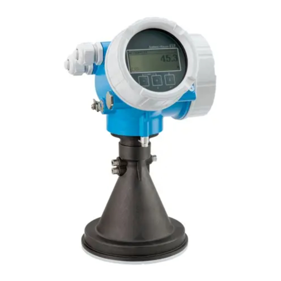
Micropilot FMR56, FMR57
PROFIBUS PA
Free space radar
These Instructions are Brief Operating Instructions; they are
not a substitute for the Operating Instructions pertaining to
the device.
Detailed information about the device can be found in the
Operating Instructions and the other documentation:
Available for all device versions via:
• Internet:
www.endress.com/deviceviewer
• Smart phone/tablet: Endress+Hauser Operations App
Solutions
Services
Advertisement
Table of Contents

Related Manuals for Endress+Hauser PROFIBUS PA Micropilot FMR56


Summary of Contents for Endress+Hauser PROFIBUS PA Micropilot FMR56
- Page 1 Operating Instructions pertaining to the device. Detailed information about the device can be found in the Operating Instructions and the other documentation: Available for all device versions via: • Internet: www.endress.com/deviceviewer • Smart phone/tablet: Endress+Hauser Operations App...
-
Page 2: Associated Documentation
Order code: XXXXX-XXXXXX Ser. no.: XXXXXXXXXXXX Ext. ord. cd.: XXX.XXXX.XX Serial number www.endress.com/deviceviewer Endress+Hauser Operations App A0023555 About this document Symbols used 2.1.1 Safety symbols DANGER This symbol alerts you to a dangerous situation. Failure to avoid this situation will result in serious or fatal injury. - Page 3 Symbols for certain types of information and graphics Permitted Procedures, processes or actions that are permitted Forbidden Procedures, processes or actions that are forbidden Tip Indicates additional information Reference to documentation Reference to graphic Notice or individual step to be observed Endress+Hauser...
-
Page 4: Basic Safety Instructions
‣ Measured process variables: level, distance, signal strength ‣ Calculated process variables: volume or mass in vessels of any shape; flow rate through measuring weirs or channels (calculated based on the level using the linearization functionality) Endress+Hauser... -
Page 5: Workplace Safety
Clarification in the case of borderline cases: ‣ For special fluids and fluids for cleaning, Endress+Hauser is glad to provide assistance in verifying the corrosion resistance of fluid-wetted materials, but does not accept any warranty or liability. -
Page 6: Incoming Acceptance And Product Identification
• Does the data on the nameplate match the order specifications on the delivery note? • Is the DVD with the operating tool present? If required (see nameplate), have the Safety Instructions (XA) been provided? If one of these conditions is not met, please contact your Endress+Hauser sales office. Storage and transport 4.2.1 Storage conditions •... - Page 7 Pay attention to the center of gravity of the device so that it does not tilt or slip unintentionally. ‣ Follow the safety instructions and transport conditions for devices over 18 kg (39.6 lbs), (IEC61010). A0016875 Endress+Hauser...
-
Page 8: Mounting Location
Use of a weather protection cover; protection from direct sunlight or rain Installation in the center, interference can cause signal loss Do not install above the filling curtain In applications with strong dust emissions, the integrated purge air connection can prevent the antenna from becoming clogged. Endress+Hauser... - Page 9 Micropilot FMR56, FMR57 PROFIBUS PA Mounting Orientation Internal vessel fittings A0018946 Avoid the location of internal fittings (limit switches, temperature sensors, struts etc.) inside the signal beam. Take into account the beam angle. Endress+Hauser...
-
Page 10: Beam Angle
The beam angle is defined as the angle α at which the energy density of the radar waves reaches half the value of the maximum energy density (3dB width). Microwaves are also emitted outside the signal beam and can be reflected off interfering installations. Endress+Hauser... - Page 11 2.10 m (6.9 ft) 20 m (66 ft) 3.50 m (11 ft) 2.80 m (9.2 ft) 25 m (82 ft) 4.37 m (14 ft) 3.50 m (11 ft) 30 m (98 ft) 5.25 m (17 ft) 4.20 m (14 ft) Endress+Hauser...
- Page 12 4.90 m (16 ft) 4.28 m (14 ft) Free-space installation in vessel 5.6.1 Horn antenna with slip-on flange (FMR56) Alignment If using the Micropilot with a slip-on flange in explosion-hazardous areas, observe all the specifications in the relevant Safety Instructions (XA). Endress+Hauser...
- Page 13 Nozzle diameter and height for horn antennas with slip-on flange ØD Maximum nozzle height H 80 mm (3 in) 300 mm (11.8 in) 100 mm (4 in) 400 mm (15.8 in) 150 mm (6 in) 500 mm (19.7 in) Endress+Hauser...
- Page 14 Micropilot can be swiveled by 15° in all directions with the optional alignment device. • A marking is provided on the gland to aid the alignment. This marking must be aligned towards the tank wall as much as possible. Endress+Hauser...
- Page 15 Maximum nozzle height H (valid for antennas without an antenna extension) Horn 80mm/3" 260 mm (10.2 in) Horn 100mm/4" 480 mm (18.9 in) Please contact the manufacturer' s support service for applications with nozzles that are higher than indicated in the table. Endress+Hauser...
- Page 16 500 mm (19.7 in). Interfering edges within the nozzle should be avoided. øD A0016827 5 Nozzle mounting of Micropilot FMR57 with parabolic antenna Antenna completely projects out of the nozzle Antenna completely inside the nozzle Endress+Hauser...
- Page 17 173 mm (6.81 in) < 50 mm (1.96 in) 250 mm (10 in) 236 mm (9.29 in) < 50 mm (1.96 in) Installation with hinged flange The length of the antenna must be taken into account in the case of hinged flanges. Endress+Hauser...
- Page 18 An angle of inclination of up to 15 °° in all directions can be set for the antenna axis using the alignment unit. The alignment unit is used to optimally align the radar beam with the bulk solid. A0016931 6 Micropilot FMR57 with alignment unit Endress+Hauser...
- Page 19 6 bar (87 psi) • Continuous operation: 200 to 500 mbar (3 to 7.25 psi) • Always use dry purge air • In general, only purge to the extent necessary as excess purging can cause mechanical damage (abrasion) Endress+Hauser...
-
Page 20: Container With Heat Insulation
350° 8 mm 8 mm A0032242 Unscrew the securing screw using an open-ended wrench. Rotate the housing in the desired direction. Tighten the securing screw (1.5 Nm for plastic housing; 2.5 Nm for aluminum or stainless steel housing). Endress+Hauser... -
Page 21: Turning The Display
Turn the display module to the desired position: Max. 8 × 45 ° in each direction. Feed the coiled cable into the gap between the housing and main electronics module and plug the display module into the electronics compartment until it engages. Endress+Hauser... -
Page 22: Electrical Connection
Turn the securing clamp 90 ° in the clockwise direction and, using an Allen key (3 mm), tighten the screw of the securing clamp on the electronics compartment cover with 2.5 Nm. Electrical connection Connecting requirements 6.1.1 Terminal assignment Endress+Hauser... - Page 23 Cable screen; observe cable specification Connection PROFIBUS PA / FOUNDATION Fieldbus Measuring device Switch output (open collector) 6.1.2 Device plug In the case of the device versions with a plug, the housing does not need to be opened to connect the signal cable. Endress+Hauser...
- Page 24 • Ex ia + Ex d(ia) / IS + XP Feature 020 in the product structure Feature 010 in the product structure Input voltages up to 35 V do not damage the device. Polarity-dependent FISCO/FNICO compliant according to IEC 60079-27 Endress+Hauser...
-
Page 25: Connecting The Device
Loosen the screw of the securing clamp of the connection compartment cover using an Allen key (3 mm) and turn the clamp 90 ° counterclockwise. Unscrew the connection compartment cover and check the cover seal; replace it if necessary. 6.2.2 Connecting A0036418 11 Engineering unit: mm (in) Endress+Hauser... - Page 26 12 Engineering unit: mm (in) To remove the cable from the terminal again: Using a flat-blade screwdriver ≤ 3 mm, press down on the slot between the two terminal holes Simultaneously pull the cable end out of the terminal. Endress+Hauser...
-
Page 27: Integration Into A Profibus Network
Overview of device master file (GSD) Manufacturer ID 17 (0x11) Ident number 0x1559 Profile version 3.02 GSD file Information and files available at: • www.endress.com GSD file version • www.profibus.org Setting the device address A0015686 13 Address switch in the connection compartment Endress+Hauser... -
Page 28: Hardware Addressing
The device restarts automatically and reports the current address (factory setting: 126). Configuring the address via the operating menu: Setup → Device address A0015903 15 Example of software addressing; switch 8 is set to the "ON" position; the address is defined in the operating menu (Setup → Device address). Endress+Hauser... -
Page 29: Operation Options
Micropilot FMR56, FMR57 PROFIBUS PA Operation options Operation options The device can be operated as follows: • Operation via operating menu (display) • DeviceCare / FieldCare, see Operating Instructions • SmartBlue (app), Bluetooth (optional), see Operating Instructions A0033202 16 Download link Endress+Hauser... -
Page 30: Structure And Function Of The Operating Menu
Visualization of a parameter (here: parameter with picklist) 3.1 Header containing parameter name and error symbol (if an error is active) 3.2 Picklist; marks the current parameter value. Input matrix for numbers Input matrix for alphanumeric and special characters Endress+Hauser... - Page 31 • If present, opens the help text for the function of the parameter. • In a text and numeric editor: Pressing the key briefly: • Opens the selected group. • Carries out the selected action. • Carries out the selected action. Endress+Hauser...
-
Page 32: Opening The Context Menu
The context menu is closed and the operational display appears. Calling up the menu via the context menu Open the context menu. Press to navigate to the desired menu. Press to confirm the selection. The selected menu opens. Endress+Hauser... -
Page 33: Operating Menu
PROFIBUS PA has been defined. Disabling write protection If the device is write-protected, it must first be unlocked, see Operating Instructions. BA01127F - Operating Instructions, FMR56/FMR57, PROFIBUS PA Setting the operating language Factory setting: English or ordered local language Endress+Hauser... - Page 34 Main menu 0104-1 Display language English Operation Setup Display language 0104-1 English à Deutsch Español Français Display language 0104-1 à English Deutsch Español Français Hauptmenü 0104-1 Sprache Deutsch Betrieb Setup A0029420 19 Taking the example of the local display Endress+Hauser...
-
Page 35: Configuring Level Measurement
Used for the basic calibration (Empty / Full). Setup → Bin type Optimizes the signal filters for the respective bin type. Note: ' W orkbench test' deactivates all filters. This option should exclusively be used for tests. Endress+Hauser... -
Page 36: User-Specific Applications
Select the level unit: %, m, mm, ft, in (factory setting: %) It is strongly recommended to adjust the maximum filling and draining speed to the actual process. User-specific applications To configure the parameters for user-specific applications, see: BA01127F - Operating Instructions, FMR56/FMR57, PROFIBUS PA Endress+Hauser... - Page 37 Micropilot FMR56, FMR57 PROFIBUS PA Commissioning Also, for the Expert submenu: GP01018F - Description of device parameters, FMR5x, PROFIBUS PA Endress+Hauser...
- Page 40 *71575732* 71575732 www.addresses.endress.com...