
Related Manuals for Enterasys 2H25x


Summary of Contents for Enterasys 2H25x
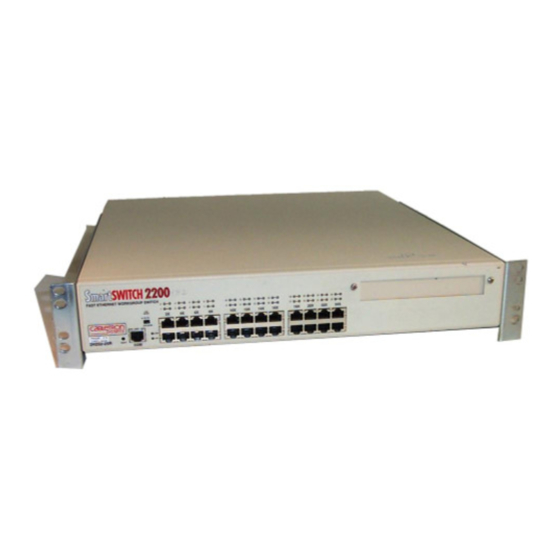
- Page 1 SmartSwitch 2200 Series Standalone Switches (2E25x and 2H25x) Local Management User’s Guide 9033069-01...
- Page 3 Enterasys Networks and its licensors reserve the right to make changes in specifications and other information contained in this document without prior notice. The reader should in all cases consult Enterasys Networks to determine whether any such changes have been made.
- Page 4 This document is an agreement (“Agreement”) between You, the end user, and Enterasys Networks, Inc. (“Enterasys”) that sets forth your rights and obligations with respect to the Enterasys software program (“Program”) in the package. The Program may be contained in firmware, chips or other media. UTILIZING THE ENCLOSED PRODUCT, YOU ARE AGREEING TO BECOME BOUND BY THE TERMS OF THIS AGREEMENT, WHICH INCLUDES THE LICENSE AND THE LIMITATION OF WARRANTY AND DISCLAIMER OF LIABILITY.
- Page 5 52.227-19 (a) through (d) of the Commercial Computer Software-Restricted Rights Clause and its successors, and (iii) in all respects is proprietary data belonging to Enterasys and/or its suppliers. For Department of Defense units, the Product is considered commercial computer software in accordance with DFARS section 227.7202-3 and its successors, and use, duplication, or disclosure by the Government is subject to restrictions set forth herein.
-
Page 7: Table Of Contents
Figures ...xii Tables...xv ABOUT THIS GUIDE Using This guide ... xvii Structure of This Guide ... xvii Related Documents...xix Document Conventions...xix Typographical and Keystroke Conventions...xx INTRODUCTION Overview ... 1-1 1.1.1 1.1.2 Navigating Local Management Screens ... 1-3 Local Management Requirements ... 1-3 Local Management Screen Elements ... - Page 8 Configuring the Trap Table ... 4-25 Entering IP Addresses ... 4-29 Enable/Disable ACL... 4-29 Setting the Reset Peak Switch Utilization ... 4-31 Image File Download Using Runtime... 4-36 Configuration File Download Using TFTP... 4-37 Configuration File Upload Using TFTP ... 4-38...
- Page 9 Setting the Age Time Field... 6-7 Setting (Enabling or Disabling) the Port Status... 6-7 Setting Switch Port Priority Port-by-Port ... 6-12 Setting Switch Port Priority on All Ports ... 6-12 Setting the TX Mapping Queues... 6-17 Setting the TX Regeneration Priorities... 6-17 Setting the Default Priority ...
- Page 10 Protocol Port Configuration Screen... 6-38 6.8.1 Example, Prioritizing Traffic According to Classification Rule... 6-41 6.9.1 6.10 Rate Limiting Configuration Screen ... 6-43 6.10.1 6.10.2 6.10.3 802.1Q VLAN CONFIGURATION MENU SCREENS Summary of VLAN Local Management... 7-2 7.1.1 802.1Q VLAN Configuration Menu Screen ... 7-3 Device VLAN Configuration Screen ...
- Page 11 VLAN Operation ... 12-6 12.5.1 12.5.2 Setting a Port to Operate Using GMRP or GVRP... 8-7 Setting All Ports on the Switch... 8-7 Setting a Mode, Port-by-Port ... 8-9 Setting a Mode for All Ports ... 8-10 Displaying Interface Statistics ... 10-8 Displaying RMON Statistics ...
- Page 12 12.9 Summary of VLAN Local Management... 12-14 12.9.1 12.10 Quick VLAN Walkthrough ... 12-15 12.11 Examples ... 12-21 12.12 Example 1, Single Switch Operation... 12-21 12.12.1 12.12.2 12.13 Example 2, VLANs Across Multiple Switches ... 12-24 12.13.1 12.13.2 12.14 Example 3, 1D Trunk Connection to 802.1Q VLAN Network... 12-31 12.14.1...
- Page 13 GENERIC ATTRIBUTE REGISTRATION PROTOCOL (GARP) GARP Switch Operation...A-1 A.1.1 A.1.2 ABOUT IGMP IGMP Overview ...B-1 Supported Features and Functions...B-2 Detecting Multicast Routers ...B-3 INDEX GARP VLAN Registration Protocol (GVRP) ...A-1 GARP Multicast Registration Protocol (GMRP) ...A-3 Contents...
-
Page 14: Figures
VLAN Redirect Configuration Screen ... 5-19 Broadcast Suppression Configuration Screen ... 5-22 802.1 Configuration Menu Screen ... 6-2 Switch Configuration Screen... 6-5 802.1 Priority Configuration Menu Screen ... 6-9 Port Priority Configuration Screen ... 6-11 Advanced Port Priority Configuration Screen ... 6-14... - Page 15 Example 7, Dynamic Egress Application... 11-25 12-1 Example of a VLAN ... 12-2 12-2 View from Inside the Switch ... 12-8 12-3 Switch Management with Only Default VLAN ... 12-11 12-4 Switch Management with VLANs ... 12-12 12-5 802.1Q VLAN Screen Hierarchy ... 12-14 12-6 Walkthrough Stage One, Static VLAN Configuration Screen...
- Page 16 12-18 Example 3, 1D Trunk Connection to 802.1Q VLAN Network ...12-32 12-19 Bridge 1 Broadcasts Frames ...12-35 12-20 Switch 2 Forwards to 1Q Trunk ...12-35 12-21 Switch 1 Forwards to 1D Trunk ...12-36 12-22 Example 4, Isolating Traffic According to Protocol ...12-38 12-23 Example 5, Filtering Traffic According to a Classification...12-42...
- Page 17 Broadcast Suppression Configuration Screen Field Descriptions ... 5-23 802.1 Configuration Menu Screen Menu Item Descriptions ... 6-3 Switch Configuration Screen Field Descriptions... 6-5 802.1 Priority Configuration Menu Screen Menu Item Descriptions ... 6-9 Port Priority Configuration Screen Field Descriptions ... 6-11 Advanced Port Priority Configuration Screen Field Descriptions ...6-15...
- Page 18 Layer 3 Extensions Menu Screen Menu Item Descriptions ...9-2 IGMP/VLAN Configuration Screen Field Descriptions ...9-5 10-1 Device Statistics Menu Screen Menu Item Descriptions ...10-3 10-2 Switch Statistics Screen Field Descriptions ...10-5 10-3 Interface Statistics Screen Field Descriptions...10-7 10-4 RMON Statistics Screen Field Descriptions...10-10...
-
Page 19: About This Guide
Welcome to the Cabletron Systems SmartSwitch 2200 Series Standalone Switches (2E25x and 2H25x) Local Management User’s Guide for SmartSwitch devices with firmware revision 4.08.11 and higher. This manual explains how to access and use Cabletron Systems Local Management for the SmartSwitch device. Local Management is a series of screens that enable the user to monitor and control the SmartSwitch device and its attached segments. - Page 20 IGMP (Internet Group Management Protocol, RFC 2236) on selected VLANs, or globally on all VLANs that are available. Chapter 10, Device Statistics Menu screens to gather statistics about the switch, interfaces, RMON, and HSIM/VHSIM and, if the device is a repeater, repeater statistics. Chapter 11, Network Tools This chapter also includes examples for each command.
-
Page 21: Related Documents
World Wide Web in Adobe Acrobat Portable Document Format (PDF) at the following site: http://www.enterasys.com/support/manuals NOTE: All documentation for the Enterasys Networks SecureFast VLAN Manager software is contained on the VLAN Manager CD-ROM. DOCUMENT CONVENTIONS The guide uses the following conventions: NOTE: Calls the reader’s attention to any item of information that may be of special... -
Page 22: Typographical And Keystroke Conventions
Typographical and Keystroke Conventions TYPOGRAPHICAL AND KEYSTROKE CONVENTIONS bold type Bold type can denote either a user input or a highlighted screen selection. RETURN Indicates either the ENTER or RETURN key, depending on your keyboard. Indicates the keyboard Escape key. SPACE bar Indicates the keyboard space bar key. -
Page 23: Introduction
Upload or download a configuration file to or from a TFTP server. • Designate which Network Management Workstations receive SNMP traps from the device. • View switch, interface, and RMON statistics. • Assign ports to operate in the standard or full duplex mode. •... -
Page 24: The Management Agent
Transmit frames on preselected destination ports according to protocol and priority or protocol and VLAN. • Configure the switch to operate as a Generic Attribute Registration Protocol (GARP) device to dynamically create VLANs across a switched network. • Configure the device to control the rate of traffic from/to the network on a per port/priority basis. -
Page 25: Navigating Local Management Screens
Out-of-band network management passes data along a medium that is entirely separate from the common data carrier of the network, for example, a cable connection between a dumb terminal and a SmartSwitch device COM port. Cabletron Systems Local Management is an out-of-band network management system. -
Page 26: Local Management Screen Elements
Local Management Screen Elements LOCAL MANAGEMENT SCREEN ELEMENTS There are six types of screens used in Local Management: password, menu, statistics, configuration, status, and warning screens. Each type of screen can consist of one to five basic elements, or fields. Figure 1-1 field follows the figure. -
Page 27: Event Messages
The following list explains each of the Local Management fields: Event Message Field This field briefly displays messages that indicate if a Local Management procedure was executed correctly or incorrectly, that changes were saved or not saved to Non-Volatile Random Access Memory (NVRAM), or that a user did not have access privileges to an application. -
Page 28: Input Fields
Local Management Screen Elements Input Fields Input Fields require the entry of keyboard characters. IP addresses, subnet mask, default gateway and device time are examples of input fields. In the screens shown in this guide, the characters in the input fields are in bold type. In the field description, the field is identified as being “modifiable”. -
Page 29: Local Management Keyboard Conventions
LOCAL MANAGEMENT KEYBOARD CONVENTIONS All key names appear as capital letters in this manual. and the key functions that are used. Table 1-2 Keyboard Conventions Function ENTER Key These are selection keys that perform the same Local Management function. For example, “Press ENTER” means that you can press either RETURN Key ENTER or RETURN, unless this manual specifically instructs you otherwise. -
Page 30: Getting Help
GETTING HELP For additional support related to the device or this document, contact Enterasys Networks using one of the following methods: World Wide Web http://www.enterasys.com/ Phone (603) 332-9400 Internet mail support@enterasys.com ftp://ftp.enterasys.com Login anonymous Password your email address To send comments or suggestions concerning this document, contact the Technical Writing Department via the following email address: TechWriting@enterasys.com... -
Page 31: Local Management Requirements
Local Management Requirements This chapter provides the following information: • Management Terminal Setup terminal to the host device. • Telnet Connections (Section access Local Management. • Monitoring an Uninterruptible Power Supply connection from the COM port to an American Power Conversion (APC) Uninterruptible Power Supply (UPS) device. -
Page 32: Console Cable Connection
Management Terminal Setup 2.1.1 Console Cable Connection Use the Console Cable Kit provided with the SmartSwitch device to attach the management terminal to the SmartSwitch device COM port as shown in To connect the SmartSwitch device to a PC or compatible device running the VT terminal emulation, proceed as follows: 1. -
Page 33: Management Terminal Setup Parameters
2.1.2 Management Terminal Setup Parameters Table 2-1 lists the setup parameters for the local management terminal. Table 2-1 VT Terminal Setup Display Setup Menu Columns -> Controls -> Auto Wrap -> Scroll -> Text Cursor -> Cursor Style -> General Setup Menu Mode ->... -
Page 34: Telnet Connections
2. Plug the RJ45 connector at the other end of the cable into the RJ45-to-DB9 male (UPS) adapter (Enterasys Systems part number, 9372066). 3. Connect the RJ45-to-DB9 male (UPS) adapter to the female DB9 port on the rear of the UPS device (refer to the particular UPS device’s user instructions for more specific information about... -
Page 35: Uninterruptible Power Supply (Ups) Connection
Monitoring an Uninterruptible Power Supply Figure 2-2 Uninterruptible Power Supply (UPS) Connection Local Management Requirements... -
Page 37: Accessing Local Management
Accessing the Password screen to enter a Local Management session • Accessing the Device Menu screen and its menu items to gain access to other screens for configuring the switch, obtaining operating statistics, and obtaining access to network tools (Section 3.3). -
Page 38: Navigating Local Management Screens
The SmartSwitch device Local Management application consists of a series of menu screens. Navigate through Local Management by selecting items from the menu screens. The SmartSwitch device supports two modes of switch operation. The switching modes are as follows: •... -
Page 39: Q Switching Mode, Lm Screen Hierarchy
Figure 3-1 802.1Q Switching Mode, LM Screen Hierarchy Device Configuration Menu General Configuration SNMP Configuration Menu System Resources Information FLASH Download Configuration Port Configuration Menu 802.1 Configuration Menu Password Switch Configuration Device 802.1Q VLAN Menu Configuration Menu 802.1 Priority Configuration Menu GARP Configuration Menu Rate Limiting Configuration... -
Page 40: Selecting Local Management Menu Screen Items
Navigating Local Management Screens Figure 3-2 SecureFast VLAN Mode, LM Screen Hierarchy Device Configuration Menu General Configuration SNMP Configuration Menu System Resources Information FLASH Download Configuration Port Configuration Menu Password Device Device Statistics Menu Menu Network Tools 3.1.1 Selecting Local Management Menu Screen Items Select items on a menu screen by performing the following steps: 1. -
Page 41: Using The Next And Previous Commands
Using the RETURN Command To exit LM using the RETURN command, proceed as follows: 1. Use the arrow keys to highlight the RETURN command at the bottom of the Local Management screen. 2. Press ENTER. The previous screen in the Local Management hierarchy displays. NOTE: The user can also exit Local Management screens by pressing ESC twice. -
Page 42: Password Screen
Password Screen PASSWORD SCREEN When to Use To start a Local Management session. Local Management is controlled through the Local Management Password screen shown in SmartSwitch device the Local Management Password screen displays. Before continuing, you must enter a password (community name), which is compared to the previously stored passwords. The level of access allowed the user depends on the password. - Page 43 Password Screen 2. Enter the Password and press ENTER. The default super-user access password is “public” or press ENTER. NOTE: The password is one of the community names specified in the SNMP Community Names Configuration screen. Access to certain Local Management capabilities depends on the degree of access accorded that community name.
-
Page 44: Device Menu Screen
To access the three major menu screens of Local Management to configure the SmartSwitch device, obtain operating statistics, access the network tools command set, and set the security access policy for the switch. How to Access Enter a valid password in the Local Management Password screen as described in press ENTER. -
Page 45: Port Configuration Menu Screens
RMON statistics information. For details, refer to MENU Chapter NETWORK The Network Tools function resides on the switch and consists of that TOOLS commands that allow you to access and manage the SmartSwitch device and also Telnet to other devices. -
Page 46: Overview Of Security Methods
Overview of Security Methods OVERVIEW OF SECURITY METHODS Three security methods are available to control which users are allowed access to the switch’s host to monitor the configuration and control of the switch. • Host Access Control List (ACL) – allows only the defined list of IP Addresses to communicate with the host for Telnet, WebView (HTTP) and SNMP. - Page 47 All radius values, except the server IPs and shared secrets, are assigned reasonable default values when radius is installed on a new switch. The defaults are as follows: • Client, disabled •...
- Page 48 IP and Shared Secret. When the Radius Client is active on the switch, you are prompted by an authorization screen for a user login name and password when attempting to access the host IP address via the local console LM, Telnet to LM, or WebView application.
-
Page 49: Security Menu Screen
Local Management Module password. If the user is connected remotely via telnet or WebView, the switch will continue to deny access until communication with the Radius Server is operational again. Optionally, if the switch has been configured to allow remote access, the switch can be configured to use the Local Management Module password in the event of a Radius failure. -
Page 50: Security Menu Screen
Used to set the Locally Administered Passwords (super user, read-write, and read-only) to access the device according to an access policy. For details, refer to RADIUS Used to configure the Radius Client Parameters on the switch, primary CONFIGURATION server, and secondary server. For details, refer to 3-14... -
Page 51: Passwords Screen
Local Management access (super-user, read-write and read-only) via serial console or telnet connection. This screen is also used to disable the function of hardware switch 8 to prevent the clearing of the login passwords. How to Access Use the arrow keys to highlight the PASSWORDS menu item on the Security Menu screen and press ENTER. -
Page 52: Module Login Passwords Screen Field Descriptions
Switch 8 Enable or disable the function of hardware switch S8 on the main (Toggle) board of the device. When set to ENABLED, S8 can be used to clear the password. When set to DISABLED, S8 cannot be used to clear the password. -
Page 53: Setting The Login Password
Access Policy. 2. Press ENTER. 3. To disable the function of switch S8 so the passwords cannot be cleared, use the arrow keys to highlight the Switch 8 field. 4. Press the SPACE bar to select DISABLED. -
Page 54: Radius Configuration Screen
RADIUS Configuration Screen How to Access Use the arrow keys to highlight the RADIUS CONFIGURATION menu item on the Security Menu screen and press ENTER. The RADIUS Configuration screen, Screen Example Figure 3-7 Radius Configuration Screen Field Descriptions Refer to Table 3-4 for a functional description of each screen field. - Page 55 Table 3-4 Radius Configuration Screen Field Descriptions (Continued) Use this field… To… Auth Port Enter the number of the Authorization UDP Port for the Primary and (Modifiable) Secondary server. Acct Port Enter the number of the Accounting UDP Port for the Primary and (Modifiable) Secondary server.
-
Page 56: Setting The Last Resort Authentication
RADIUS Configuration Screen 3.7.1 Setting the Last Resort Authentication The RADIUS client can be configured to use primary and secondary servers. If the primary server does not respond within the specified number of retries during the specified time-out period, the client will then attempt to authenticate using the secondary server. -
Page 57: Device Configuration Menu Screens
Device Configuration Menu Screens This chapter describes the Device Configuration Menu screen and the following screens that may be selected: • General Configuration screen • SNMP Configuration Menu screen • SNMP Community Names Configuration screen • SNMP Traps Configuration screen •... -
Page 58: Device Configuration Menu Screen
To access a series of Local Management screens used to establish an Access Control List (ACL) to provide additional security, configure and monitor operating parameters, modify SNMP community names, set SNMP traps, configure switch parameters, and configure the SmartSwitch device ports. -
Page 59: Garp Configuration Menu Screens
(FLASH memory, INFORMATION DRAM and NVRAM) in the device and the unused portion of each memory; and displays the current CPU (switch) utilization and the peak switch utilization. For details, refer to FLASH... -
Page 60: General Configuration Screen
Configuration Menu screen and press ENTER. The General Configuration screen, displays. Device Configuration Menu Screens NOTE: The Layer 3 Extensions Menu and IGMP/VLAN Configuration screens display only if the SmartSwitch device has been configured to operate in the 802.1Q switch mode. Chapter Figure 4-2,... -
Page 61: General Configuration Screen
Screen Example Figure 4-2 General Configuration Screen Field Descriptions Refer to Table 4-2 for a functional description of each screen field. Table 4-2 General Configuration Screen Field Descriptions Use this field… To… MAC Address See the base physical address of the SmartSwitch device. (Read-Only) IP Address See the IP address for the SmartSwitch device. - Page 62 General Configuration Screen Table 4-2 General Configuration Screen Field Descriptions (Continued) Use this field… To… Subnet Mask See the subnet mask for the SmartSwitch device. A subnet mask (Modifiable) “masks out” the network bits of the IP address by setting the bits in the mask to 1 when the network treats the corresponding bits in the IP address as part of the network or subnetwork address, or to 0 if the corresponding bit identifies the host.
- Page 63 Device Uptime See the total time that the device has been operating. (Read-Only) Operational Mode Set the SmartSwitch device to operate as either an IEEE 802.1Q switch (Toggle) (802.1Q SWITCHING option) or as a SecureFast switch (SECURE FAST VLAN option).
-
Page 64: Setting The Ip Address
General Configuration Screen Table 4-2 General Configuration Screen Field Descriptions (Continued) Use this field… To… IP Fragmentation Enable or disable IP Fragmentation. The default setting for this field is (Toggle) ENABLED. If the SmartSwitch device is to be bridged to an FDDI ring using an HSIM-F6, IP Fragmentation should be enabled. -
Page 65: Setting The Subnet Mask
Figure 4-3 Configuration Warning Screen, IP Address 5. Use the arrow keys to highlight the YES command, then press ENTER. The changes are saved and the device reboots. 4.2.2 Setting the Subnet Mask If the management workstation that is to receive SNMP traps from the SmartSwitch device is located on a separate subnet, the subnet mask for the SmartSwitch device may need to be changed from its default value. -
Page 66: Setting The Default Gateway
General Configuration Screen 4. Use the arrow keys to highlight the SAVE command, then press ENTER. The warning screen shown in Figure 4-4 displays. Figure 4-4 Configuration Warning Screen, Subnet Mask 5. Use the arrow keys to highlight the YES command, then press ENTER. The changes are saved and the device reboots. -
Page 67: Setting The Tftp Gateway Ip Address
3. Press ENTER. If the default gateway entered is in the correct format, the cursor returns to the beginning of the Default Gateway field. If the format is not correct, the screen displays “INVALID DEFAULT GATEWAY OR FORMAT ENTERED”. Local Management does not alter the current value, but it does refresh the Default Gateway field with the previous value. -
Page 68: Setting The Device Time
General Configuration Screen 3. Press ENTER to set the system calendar to the date in the input field. 4. Use the arrow keys to highlight the SAVE command at the bottom of the screen and press ENTER. If the date entered is a valid format, the message displays “SAVED OK” at the top of the screen. If the entry is not valid, Local Management does not alter the current value, but it does refresh the Device Date field with the previous value. -
Page 69: Entering A New Screen Refresh Time
4.2.7 Entering a New Screen Refresh Time The screen refresh time can be set from 3 to 99 seconds with a default of 3 seconds. To set a new screen refresh time, perform the following steps: 1. Use the arrow keys to highlight the Screen Refresh Time field. 2. -
Page 70: Setting The Operational Mode
General Configuration Screen 4.2.9 Setting the Operational Mode NOTE: If the device is to be configured to operate as a SecureFast switch, the device must be assigned an IP address. To set the Operational Mode, proceed as follows: 1. Use the arrow keys to highlight the Operational Mode field. -
Page 71: Configuring The Com Port
IP address and the COM port has been disabled or the settings changed, reset NVRAM on the SmartSwitch device using Mode Switch 7 to reestablish COM port communications. For details about Switch 7 and its operation, refer to the SmartSwitch device installation user’s guide shipped with your SmartSwitch... -
Page 72: Com Port Warning
General Configuration Screen 2. Press the SPACE bar to choose either ENABLED or DISABLED. The COM port must be ENABLED for the LM or UPS application. Selecting DISABLED disallows the COM port connection to the terminal, providing additional device security. CAUTION: If the COM port is reconfigured without a valid IP address set on the SmartSwitch device, the message shown in Do not continue unless the outcome of the action is fully understood. -
Page 73: Com Port Application Settings
4.2.10.1 Changing the COM Port Application After enabling the COM port as described in the COM port (LM or UPS) can be selected. The default application is LM. To change the COM port application: 1. Use the arrow keys to highlight the Application field. 2. -
Page 74: Clear Nvram Warning
General Configuration Screen 3. Use the arrow keys to highlight SAVE at the bottom of the screen. 4. Press ENTER. The warning shown in Figure 4-7 Clear NVRAM Warning 5. To clear the NVRAM, use the arrow keys to select YES and press ENTER. The message “CLEARING NVRAM. -
Page 75: Snmp Configuration Menu Screen
To provide access to the SNMP Community Names Configuration, SNMP Traps Configuration, and Access Control List screens. These screens are used to modify SNMP community names, set SNMP traps, and establish an access control list to provide additional switch security. How to Access Use the arrow keys to highlight the SNMP CONFIGURATION MENU item on the DEVICE CONFIGURATION MENU screen, and press ENTER. -
Page 76: Snmp Configuration Menu Screen Menu Item Descriptions
SNMP Configuration Menu Screen Menu Descriptions Refer to Table 4-4 for a functional description of each menu item. Table 4-4 SNMP Configuration Menu Screen Menu Item Descriptions Menu Item Screen Function SNMP Used to enter new, change, or review the community names used as COMMUNITY access passwords for device management operation. -
Page 77: Snmp Community Names Configuration Screen
SNMP COMMUNITY NAMES CONFIGURATION SCREEN When to Use To set SNMP Management community names. Community names act as passwords to Local/Remote Management and are agents of security access to the SmartSwitch device. Access is controlled by enacting any of three different levels of security authorization (read-only, read-write, and super-user). -
Page 78: Snmp Community Names Configuration Screen Field Descriptions
SNMP Community Names Configuration Screen Field Descriptions Refer to Table 4-5 for a functional description of each screen field. Table 4-5 SNMP Community Names Configuration Screen Field Descriptions Use this field… To… Community Name Enter the user-defined name through which a user accesses the (Modifiable) SmartSwitch device SNMP Management. -
Page 79: Establishing Community Names
4.4.1 Establishing Community Names The password used to access Local Management at the Password Screen must have super-user access to view and edit the SNMP Community Names Configuration screen. Using a password with read-only or read-write access does not allow the viewing or editing of the SNMP Community Names Configuration screen. -
Page 80: Snmp Traps Configuration Screen
SNMP Traps Configuration Screen SNMP TRAPS CONFIGURATION SCREEN When to Use To assign SNMP traps to eight different IP addresses. Since the SmartSwitch device is an SNMP compliant device, it can send messages to multiple Network Management Stations to alert users of status changes. -
Page 81: Snmp Traps Configuration Screen Field Descriptions
Field Descriptions Refer to Table 4-6 for a functional description of each screen field. Table 4-6 SNMP Traps Configuration Screen Field Descriptions Use this field… To… Trap Destination Display/enter the IP address of the workstation to receive trap alarms. (Modifiable) Up to eight different destinations can be defined. -
Page 82: Access Control List Screen
Access Control List Screen 7. Use the arrow keys to highlight the SAVE command and press ENTER. The message “SAVED OK” displays on the screen. NOTE: Exiting without saving causes a “NOT SAVED?” message to appear above the SAVE command. Edits are lost if they are not saved before exiting. The designated workstations will now receive traps from the SmartSwitch device as long as the communication path to the designated workstations is not inhibited (for example, by subnets or VLANs). -
Page 83: Access Control List Screen
Access Control List Screen Screen Example Figure 4-11 Access Control List Screen Device Configuration Menu Screens 4-27... -
Page 84: Access Control List Screen Field Descriptions
Access Control List Screen Field Descriptions Refer to Table 4-7 for a functional description of each screen field. Table 4-7 Access Control List Screen Field Descriptions Use this field… To… Access Control Lists Enable or disable to restrict SNMP/IP access to a limited number of IP (Toggle) addresses. -
Page 85: Entering Ip Addresses
4.6.1 Entering IP Addresses To enter IP addresses into the ACL, proceed as follows: 1. Use the arrow keys to highlight one of the place holders (0.0.0.0) under IP Addresses. 2. Enter the IP address of a device that you want to have access to Local Management using the following format: nn.nn.nn.nn (where n is an alphanumeric character) 3. -
Page 86: System Resources Information Screen
SYSTEM RESOURCES INFORMATION SCREEN When to Use To monitor the current switch utilization and the peak switch utilization. This screen provides information concerning the processor used in the SmartSwitch device and the amount of FLASH memory, DRAM, and NVRAM that is installed and how much of that memory is available. -
Page 87: System Resources Information Screen Field Descriptions
4.7.1 Setting the Reset Peak Switch Utilization To set the Reset Peak Switch Utilization field to YES or NO, proceed as follows: 1. Use the arrow keys to highlight the Reset Peak Switch Utilization field. 2. Press the SPACE bar to select YES or NO. -
Page 88: Flash Download Configuration Screen
• Upload the configuration file from the SmartSwitch device to a TFTP server. NOTE: To force an image download, change the position of Switch 6 located inside the device; refer to your SmartSwitch device installation user’s guide for details. Before downloading an image to the device, copy the image to the network TFTP server. -
Page 89: Flash Download Configuration Screen
FLASH Download Configuration Screen How to Access Use the arrow keys to highlight the FLASH DOWNLOAD CONFIGURATION menu item on the Device Configuration Menu screen, and press ENTER. The Flash Download Configuration screen, Figure 4-13, displays. Screen Example Figure 4-13 Flash Download Configuration Screen nnn.nnn.nnn.nnn Device Configuration Menu Screens 4-33... -
Page 90: Flash Download Configuration Screen Field Descriptions
FLASH Download Configuration Screen Field Descriptions Refer to Table 4-9 for a functional description of each screen field. Table 4-9 Flash Download Configuration Screen Field Descriptions Use this field… To… Download Method Select a method (RUNTIME, DOWNLOAD CONFIG, or UPLOAD (Selectable) CONFIG) to download (receive) an image file from a TFTP server, or upload (transmit) or download a configuration file to/from a TFTP... - Page 91 Table 4-9 Flash Download Configuration Screen Field Descriptions (Continued) Use this field… To… Reboot After Set the SmartSwitch device so it will either reboot or not reboot after Download completing the download of an image. This field toggles between YES (Toggle) and NO, when the Download Method field is set to RUNTIME.
-
Page 92: Image File Download Using Runtime
FLASH Download Configuration Screen 4.8.1 Image File Download Using Runtime To download a firmware image file to the SmartSwitch device using Runtime, proceed as follows: 1. Use the arrow keys to highlight the Reboot After Download field. 2. Use the SPACE bar to select either YES or NO. Select YES if you want the device to reboot after the download is completed. -
Page 93: Configuration File Download Using Tftp
4.8.2 Configuration File Download Using TFTP To download a configuration file from a TFTP server to the SmartSwitch device, proceed as follows: 1. Use the arrow keys to highlight the Download Method field. 2. Use the SPACE bar to select DOWNLOAD CONFIG. NOTE: When DOWNLOAD CONFIG is selected, the Reboot After Download field is automatically set to YES (and cannot be changed), so that the SmartSwitch device automatically reboots after a successful download. -
Page 94: Configuration File Upload Using Tftp
FLASH Download Configuration Screen 4.8.3 Configuration File Upload Using TFTP To upload a configuration file to a TFTP server, proceed as follows: 1. Use the arrow keys to highlight the Download Method field. 2. Use the SPACE bar to select UPLOAD CONFIG. NOTE: When Upload Config is selected, the Reboot After Download field is automatically set to NO (and cannot be changed). -
Page 95: Port Configuration Menu Screens
Port Configuration Menu Screens This chapter describes the Port Configuration Menu screen and the following screens that may be selected: • Ethernet Interface Configuration screen • Ethernet Port Configuration screen • HSIM/VHSIM Configuration screen • Redirect Configuration Menu screen • Port Redirect Configuration screen •... -
Page 96: Port Configuration Menu Screen
Port Configuration Menu Screen How to Access Use the arrow keys to highlight the PORT CONFIGURATION MENU item on the Device Configuration Menu screen and press ENTER. The Port Configuration Menu screen, screen displays. Screen Example Figure 5-1 Port Configuration Menu Screen Menu Descriptions Refer to Table 5-1... -
Page 97: Ethernet Interface Configuration Screen
Table 5-1 Port Configuration Menu Screen Menu Item Descriptions (Continued) Menu Item Screen Function HSIM/VHSIM Provides access to the HSIM or VHSIM setup screen, depending on the CONFIGURATION one installed in the device. The screens for optional non-Ethernet HSIMs and VHSIMs are described in their respective user’s guides. For details, refer to REDIRECT When the operational mode is set for 802.1Q SWITCHING, this menu... -
Page 98: Ethernet Interface Configuration Screen
Ethernet Interface Configuration Screen How to Access Use the arrow keys to highlight the ETHERNET INTERFACE CONFIGURATION menu item on the Port Configuration Menu screen and press ENTER. The Ethernet Interface Configuration screen, Figure 5-2, displays. Screen Example Figure 5-2 Ethernet Interface Configuration Screen Field Descriptions Refer to Table 5-2... - Page 99 Table 5-2 Ethernet Interface Configuration Screen Field Descriptions (Continued) Use this field… To… Port Type See the type of interface using the name of the physical port type. For (Read-Only) the Ethernet 10/100 Mbps ports in the SmartSwitch device, FE-100TX will be displayed.
- Page 100 Ethernet Interface Configuration Screen Table 5-2 Ethernet Interface Configuration Screen Field Descriptions (Continued) Use this field… To… FDX FC See the current full duplex flow control setting. Flow control is used to (Read-Only) manage the transmission between two devices as specified by IEEE 802.3x to prevent receiving ports from being overwhelmed by frames from transmitting devices.
-
Page 101: Ethernet Port Configuration Screen
Ethernet Port Configuration Screen ETHERNET PORT CONFIGURATION SCREEN When to Use To change the operating mode of a specific Ethernet interface, such as the speed, duplex, auto-negotiation, advertised ability, and the flow control settings. Configuring optional Fast Ethernet or Gigabit Ethernet ports is also done on this screen. How to Access Use the arrow keys to highlight the desired Ethernet port on the Ethernet Interface Configuration screen and press ENTER. -
Page 102: Ethernet Port Configuration Screen Field Descriptions
Ethernet Port Configuration Screen Field Descriptions Refer to Table 5-3 for a functional description of each screen field. Table 5-3 Ethernet Port Configuration Screen Field Descriptions Use this field… To… Interface See the Interface number. (Read-Only) Physical Port See the number of the physical port on the interface. (Read-Only) Default Speed See the current operational speed in Mbps. - Page 103 Table 5-3 Ethernet Port Configuration Screen Field Descriptions (Continued) Use this field… To… Advertised Ability Select the port advertised mode of operation. In normal operation, with (Selectable) all capabilities enabled, the port “advertises” that it has the ability to operate in any mode. The user may choose to set up the port so that only a portion of the available capabilities are advertised and the others are disabled.
- Page 104 Ethernet Port Configuration Screen Table 5-3 Ethernet Port Configuration Screen Field Descriptions (Continued) Use this field… To… Full Duplex Flow Set the flow control feature on each port for a specific mode. The Control choices are as follows: (Selectable) Symmetric – the port operates in Symmetric mode, causing the port to interpret received PAUSE frames and allow the port to transmit PAUSE frames when necessary at any speed connection.
-
Page 105: Selecting Settings
5.3.1 Selecting Settings All selectable or toggle fields other than Advertised Ability can be changed by following this procedure: 1. Use the arrow keys to highlight the field to be changed. 2. Use the SPACE bar or BACKSPACE key to step or toggle through the selections. 3. -
Page 106: Hsim/Vhsim Configuration Screen
HSIM/VHSIM Configuration Screen HSIM/VHSIM CONFIGURATION SCREEN When to Use To configure an optional HSIM or VHSIM. NOTE: The HSIM/VHSIM Configuration menu item can only be selected when a non-Ethernet HSIM or VHSIM is installed in the SmartSwitch device. When selected, the applicable setup screen for that interface displays. -
Page 107: Redirect Configuration Menu Screen
Table 5-4 Redirect Configuration Menu Screen Menu Item Descriptions Menu Item Screen Function PORT REDIRECT Used to redirect traffic from a source switch port to a destination CONFIGURATION switch port. For details, refer to VLAN REDIRECT Used to configure the device to direct traffic from a VLAN to a CONFIGURATION particular switch port. -
Page 108: Port Redirect Configuration Screen
Redirect Configuration Menu screen and press ENTER. The Port Redirect Configuration screen, Figure 5-5, displays. NOTE: When the SmartSwitch device is operating as a SecureFast VLAN switch, the Port Redirect Configuration screen is the only redirect screen that displays. 5-14... -
Page 109: Port Redirect Configuration Screen
Figure 5-5 Port Redirect Configuration Screen Field Descriptions Refer to Table 5-5 for a functional description of each screen field. Table 5-5 Port Redirect Configuration Screen Field Descriptions Use this field… To… Source Port See which ports are currently set as source ports. (Read-Only) Destination Port See which ports are currently set as destination ports. -
Page 110: Changing Source And Destination Ports
Port Redirect Configuration Screen Table 5-5 Port Redirect Configuration Screen Field Descriptions (Continued) Use this field… To… Redirect Errors See whether the corresponding source ports are configured ON to send (Read-Only) errored frames to the destination ports, or OFF to drop all errored frames and only forward valid frames to the destination ports. - Page 111 5. Use the arrow keys to highlight the Frame Format field near the bottom of the screen. 6. Use the SPACE bar or BACKSPACE key to step to the appropriate frame format setting (NORMAL, TAGGED, or UNTAGGED) for the selected Destination Port. 7.
-
Page 112: Vlan Redirect Configuration Screen
VLAN Redirect Configuration Screen VLAN REDIRECT CONFIGURATION SCREEN NOTE: When the SmartSwitch device is operating as a SecureFast VLAN switch, this screen will not display. The Port Redirect Configuration screen is the only redirect screen that will display. When to Use To select a source VLAN ID and a destination port. -
Page 113: Vlan Redirect Configuration Screen
Screen Example Figure 5-6 VLAN Redirect Configuration Screen Field Descriptions Refer to Table 5-6 for a functional description of each screen field. Table 5-6 VLAN Redirect Configuration Screen Field Descriptions Use this field… To… Source VLAN See the VLAN ID of the VLANs that are currently set as source (Read-Only) VLANs. -
Page 114: Changing Source Vlan And Destination Ports
VLAN Redirect Configuration Screen Table 5-6 VLAN Redirect Configuration Screen Field Descriptions Use this field… To… Frame Format See the current frame format setting: RECEIVED, TAGGED or (Read-Only) UNTAGGED. The default is RECEIVED. • • • Redirect Errors Unsupported. Source VLAN [n] Enter the VLAN ID of the VLAN that is to be changed to a source (Modifiable) VLAN. - Page 115 3. Use the arrow keys to highlight the Destination Port field near the bottom of the screen. 4. Use the SPACE bar or BACKSPACE key to step to the appropriate port number for the destination port. 5. Use the arrow keys to highlight the Frame Format field near the bottom of the screen. 6.
-
Page 116: Broadcast Suppression Configuration Screen
NOTE: The Broadcast Suppression Configuration screen is not available if the operational mode of the device is set to SECURE FAST VLAN. This screen can only be used when the device is configured to operate as an 802.1Q switch. describes how to set the operational mode. -
Page 117: Broadcast Suppression Configuration Screen Field Descriptions
Field Descriptions Refer to Table 5-7 for a functional description of each screen field. Table 5-7 Broadcast Suppression Configuration Screen Field Descriptions Use this field… To… PORT # Identify the number of the port. (Read-Only) Total RX See the total number of broadcast frames received. (Read-Only) Peak Rate See the highest number of broadcast frames received in a one-second... -
Page 118: Setting The Reset Peak
Broadcast Suppression Configuration Screen 5.8.2 Setting the Reset Peak To set the Reset Peak field to YES or NO, proceed as follows: 1. Use the arrow keys to highlight the Reset Peak field for the selected port. 2. Press the SPACE bar to select YES or NO. 3. -
Page 119: Configuration Menu Screens
This chapter describes the 802.1 Configuration Menu screen and the following screens that may be selected from its menu: NOTE: The following screens are not available when the SmartSwitch device is operating in the SecureFast mode. • Switch Configuration screen • 802.1Q VLAN Configuration Menu screen • 802.1 Priority Configuration Menu screen •... -
Page 120: Configuration Menu Screen
802.1 CONFIGURATION MENU SCREEN When to Use To access the Switch Configuration, 802.1Q VLAN Configuration Menu, 802.1 Priority Configuration Menu, GARP Configuration Menu, and Rate Limiting Configuration screens. NOTE: The 802.1 Configuration Menu screen is not available if the operational mode of the device is set to SECURE FAST VLAN. -
Page 121: Configuration Menu Screen Menu Item Descriptions
CONFIGURATION Details about VLANs, how to configure them, and examples showing MENU how to configured the switch for VLANs to solve a given problems are described in Configuration screens, refer to This screen displays only if the SmartSwitch device has been configured to operate as an IEEE 802.1Q switch as described in... -
Page 122: Switch Configuration Screen
Switch Configuration Screen SWITCH CONFIGURATION SCREEN NOTE: The Switch Configuration screen is not available if the operational mode of the device is set to SECURE FAST VLAN. This screen can only be used when the device is configured to operate as an 802.1Q switch. -
Page 123: Switch Configuration Screen
ATM ports that will display on this screen. Type of STA Set the method (Spanning Tree Algorithm) that switches use to decide (Toggle) which SmartSwitch device is the controlling (Root) switch. Valid selection is IEEE, DEC, and None. To set the STA, refer to Section 6.2.1. - Page 124 Switch Configuration Screen Table 6-2 Switch Configuration Screen Field Descriptions (Continued) Use this field… To… Age Time Set the amount of time (in seconds) that the SmartSwitch device keeps (Modifiable) an address in its filtering database before discarding it. An address is automatically discarded when a valid frame is not received from that address within the time specified in the Age Time field.
-
Page 125: Setting The Sta
The Spanning Tree Algorithm (STA) setting is used to set the method that the SmartSwitch devices use to decide which is the controller (Root) switch when two or more switches are in parallel. The available selections are IEEE, DEC, and NONE. -
Page 126: Priority Configuration Menu Screen
802.1 Priority Configuration Menu Screen 802.1 PRIORITY CONFIGURATION MENU SCREEN NOTE: The 802.1 Priority Configuration Menu screen does not display when the operational mode of the device is set to SECURE FAST VLAN. Section 4.2.9 provides instructions for setting the operational mode. When to Use To access the Port Priority Configuration, Advanced Port Priority Configuration, Transmit Queues Configuration, and Priority Classification Configuration screens. -
Page 127: Priority Configuration Menu Screen
Figure 6-3 802.1 Priority Configuration Menu Screen Menu Descriptions Refer to Table 6-3 for a functional description of each screen menu item. Table 6-3 802.1 Priority Configuration Menu Screen Menu Item Descriptions Menu Item Screen Function PORT PRIORITY Used to set the port default transmit priority (0 through 7) of each port CONFIGURATION for frames that are received without priority information in their tag header. -
Page 128: Port Priority Configuration Screen
Port Priority Configuration Screen Table 6-3 802.1 Priority Configuration Menu Screen Menu Item Descriptions (Continued) Menu Item Screen Function PRIORITY Used to assign transmit priorities to protocol types of received frames CLASSIFICATION and to access the Protocol Port Configuration screen to add or delete CONFIGURATION transmitting ports associated with a specific priority. -
Page 129: Port Priority Configuration Screen
Screen Example Figure 6-4 Port Priority Configuration Screen Field Descriptions Refer to Table 6-4 for a functional description of each screen field. Table 6-4 Port Priority Configuration Screen Field Descriptions Use this field … To… Port # See the list of switched ports on the device. (Read-Only) Priority Select the transmit priority of frames received without the priority... -
Page 130: Setting Switch Port Priority Port-By-Port
To set the port priority on all ports, proceed as follows: 1. Use the arrow keys to highlight the Set All Switch Port’s Priority field. 2. Press the SPACE bar to select a priority from 0 through 7 (0 is the lowest priority). -
Page 131: Advanced Port Priority Configuration Screen
ADVANCED PORT PRIORITY CONFIGURATION SCREEN NOTE: The Advanced Port Priority Configuration screen does not display when the operational mode of the device is set to SECURE FAST VLAN. Section 4.2.9 provides instructions for setting the operational mode. When to Use To set the Priority/Queue Mapping and Priority Regeneration for a particular port and also can be used to change the default port priority used in the device. -
Page 132: Advanced Port Priority Configuration Screen
Advanced Port Priority Configuration Screen How to Access Use the arrow keys to highlight the ADVANCED PORT PRIORITY CONFIGURATION menu item on the 802.1 Priority Configuration Menu screen and press ENTER. The Advanced Port Priority Configuration screen, Figure 6-5, displays. Screen Example Figure 6-5 Advanced Port Priority Configuration Screen 6-14... -
Page 133: Advanced Port Priority Configuration Screen Field Descriptions
Field Descriptions Refer to Table 6-5 for a functional description of each screen field. Table 6-5 Advanced Port Priority Configuration Screen Field Descriptions Use this field… To… Priority See the list of the eight priorities, 0 through 7. (Read-Only) TX Queue Enable the frames with a certain priority to be mapped to transmit (Selectable) according to one of four TX queues (0 through 3) with 0 being the... - Page 134 Advanced Port Priority Configuration Screen Table 6-5 Advanced Port Priority Configuration Screen Field Descriptions (Continued) Use this field… To… TX Priority Enable the frames with a certain RX priority to be changed to transmit (Selectable) according to a different TX priority (0 through 7) within the device. The following describes how frames of learned traffic are handled within the device.
-
Page 135: Setting The Tx Mapping Queues
6.5.1 Setting the TX Mapping Queues To set the TX queue for frames with a particular priority, proceed as follows: 1. Use the arrow keys to highlight the Port # field. 2. Type in the number of the port to which the TX queue setting will be applied. 3. -
Page 136: Transmit Queues Configuration Screen
Transmit Queues Configuration Screen 2. Type in the number of the port having the default priority changed. 3. Use the arrow keys to highlight the Default Priority field at the bottom of the screen. The screen refreshes and displays the current settings of the port in the Port # field. 4. -
Page 137: Transmit Queues Configuration Screen
Transmit Queues Configuration Screen How to Access Use the arrow keys to highlight the TRANSMIT QUEUES CONFIGURATION menu item on the 802.1 Priority Configuration Menu screen and press ENTER. The Transmit Queues Configuration screen, Figure 6-6, displays. Screen Example Figure 6-6 Transmit Queues Configuration Screen 802.1 Configuration Menu Screens 6-19... -
Page 138: Transmit Queues Configuration Screen Field Descriptions
Transmit Queues Configuration Screen Field Descriptions Refer to Table 6-6 for a functional description of each screen field. Table 6-6 Transmit Queues Configuration Screen Field Descriptions Use this field … To… Current Queueing Toggle between the STRICT 802.1 and WEIGHTED mode. The Mode default setting is STRICT 802.1. -
Page 139: Setting The Current Queueing Mode
6.6.1 Setting the Current Queueing Mode To set the current queueing mode for a particular port, proceed as follows: 1. Use the arrow keys to highlight the Port field. 2. Press the SPACE bar to step to the appropriate port number. The port type displays to the right of the Port number field. -
Page 140: Priority Classification Configuration Screen
Priority Classification Configuration Screen PRIORITY CLASSIFICATION CONFIGURATION SCREEN NOTE: The Priority Classification Configuration screen does not display when the operational mode of the device is set to SECURE FAST VLAN. Section 4.2.9 provides instructions for setting the operational mode. When to Use To perform the following functions: •... -
Page 141: Priority Classification Configuration Screen
Screen Example Figure 6-7 Priority Classification Configuration Screen Field Descriptions Refer to Table 6-7 for a functional description of each screen field. Table 6-7 Priority Classification Configuration Screen Field Descriptions Use this field … To… See the Priority Identifications (PIDs) currently associated with –... - Page 142 Priority Classification Configuration Screen Table 6-7 Priority Classification Configuration Screen Field Descriptions (Continued) Use this field … To… Enter the PID that will be associated with the classification selected in – bottom of screen the Classification field. A PID from 0 to 7 may be typed into the field, (Modifiable) where 0 is the lowest priority and 7 is the highest priority.
-
Page 143: Classification List
Table 6-8 provides a list of the Classifications that can be selected in the Classification field and the associated subclassifications. NOTE: bold type in the table indicates a user entry. Table 6-8 Classification List Classification Ethernet II Type> 802.3 SAP> New IP TOS: - NO CHANGE - TOS=PID... - Page 144 Priority Classification Configuration Screen Table 6-8 Classification List (Continued) Classification IP TOS New IP TOS: - NO CHANGE - TOS=PID - CUSTOM> IP Protocol Type New IP TOS: - NO CHANGE - TOS=PID - CUSTOM> Same Same Same Same Same IPX COS IPX Packet Type 6-26...
- Page 145 Table 6-8 Classification List (Continued) Classification Src IP Address New IP TOS: - NO CHANGE - TOS=PID - CUSTOM> Dest IP Address New IP TOS: - NO CHANGE - TOS=PID - CUSTOM> Bil IP Address New IP TOS: - NO CHANGE - TOS=PID - CUSTOM>...
- Page 146 Priority Classification Configuration Screen Table 6-8 Classification List (Continued) Classification Dest IPX Network Bil IPX Network Src UDP Port New IP TOS: - NO CHANGE - TOS=PID - CUSTOM> Same Same Same Same Same Same Same Same Same Same Same Same Same Same...
- Page 147 Table 6-8 Classification List (Continued) Classification Bil UDP Port Same selections as for Src UDP Port Src TCP Port New IP TOS: - NO CHANGE - TOS=PID - CUSTOM> Same Same Same Same Same Same Same Same Same Same Same Same Same Same...
- Page 148 Priority Classification Configuration Screen Table 6-8 Classification List (Continued) Classification Bil TCP Port Same selections as for Src TCP Port Src IPX Socket Dest IPX Socket Bil IPX Socket Src MAC Address Dest MAC Address Bil MAC Address 6-30 802.1 Configuration Menu Screens Subclassification and Options TCP Port:...
- Page 149 Table 6-8 Classification List (Continued) Classification IP Fragments New IP TOS: - NO CHANGE - TOS=PID - CUSTOM> IP Fragments New IP TOS: - NO CHANGE - TOS=PID - CUSTOM> Dest UDP Range New IP TOS: - NO CHANGE - TOS=PID - CUSTOM>...
-
Page 150: Classification Precedence Rules
When there are multiple classifications assigned to a switch module, the switch module must determine which classification takes precedence according to the Classification Precedence Rules. -
Page 151: Classification Precedence
Table 6-9 lists the ISO Layer, associated classification and precedence levels. NOTE: In Table 6-9 – Highest precedence is 1a. – Lowest precedence is 6. – Exact Match indicates a match of an explicitly defined address. – Best Match indicates a match of an entire subnet, or range of addresses within a subnet. - Page 152 Priority Classification Configuration Screen Table 6-9 Classification Precedence (Continued) Classification Type Layer 3 (Continued) Source IPX Network Number Destination IPX Network Number IP Fragments Layer 4 UDP Port Source UDP Port Destination TCP Source Port TCP Destination Port IPX Socket Source IPX Socket Destination UDP Source Port UDP Source Port Range...
- Page 153 3. This is because the TCP port number classifications take precedence over IP TOS classifications. The key thing to remember is that the switch module will classify frames based on one of the classification options.
-
Page 154: Datagram, Layer 2 And Layer 3
Figure 6-8 Datagram, Layer 2 and Layer 3 This IP TOS Rewrite feature enables a Network Administrator to assign Layer 3 TOS characteristics to incoming frames and setting the switch to rewrite the 8-bit TOS value in the Layer 3 information portion of incoming frames. -
Page 155: Assigning A Classification To A Pid
6.7.4 Assigning a Classification to a PID NOTE: It is strongly recommended that you read concerning classification before configuring the SmartSwitch device. Incorrect configuration will affect network operation. To add a Classification Rule, proceed as follows: 1. Use the arrow keys to highlight the PID (priority identification) field. 2. -
Page 156: Deleting Pid/Classification/Description Line Items
Protocol Port Configuration Screen 6.7.5 Deleting PID/Classification/Description Line Items All, or one or more, line items can be deleted as follows: Deleting All Line Items To delete all configured Classification Rules, use the arrow keys to highlight the DEL ALL command field and press ENTER. -
Page 157: Protocol Port Configuration Screen
Screen Example Figure 6-9 Protocol Port Configuration Screen Field Descriptions Refer to Table 6-10 for a functional description of each screen field. Table 6-10 Protocol Port Configuration Screen Field Descriptions Use this field… To… Classification Rule See the Classification Rule (Priority, Classification, and Definition) of (Read-Only) the line selected on the Priority Classification Configuration screen. -
Page 158: Assigning Ports To A Pid/Classification
Protocol Port Configuration Screen Table 6-10 Protocol Port Configuration Screen Field Descriptions (Continued) Use this field… To… Port See the number of each port. (Read-Only) Classify See which ports are set to the PID/Classification indicated in the (Toggle) Classification Rule field (see between YES and NO, which determines whether or not the associated port is set to the Classification Rule. -
Page 159: Example, Prioritizing Traffic According To Classification Rule
Solving the Problem In this example, switches S1 and S2 have already been configured and are operating. The following covers only the additional steps needed to configure each switch to establish the priority for each server. NOTE: For optimal operation of the prioritizing function, the connection between S1 and S2 is set for 802.1Q tagging. - Page 160 4. Assign all ports on the SmartSwitch device to use this classification setting. Switch 2 The Switch 1 setup instructions are repeated to set up Switch 2. NOTE: For optimal operation of the prioritizing function, the connection between S1 and S2 is set for 802.1Q tagging.
-
Page 161: Rate Limiting Configuration Screen
Rate Limiting Configuration Screen 6.10 RATE LIMITING CONFIGURATION SCREEN NOTE: The Rate Limiting function is not supported on SmartTrunk ports. When to Use To limit the rate of traffic entering and leaving the SmartSwitch device on a per port/priority basis. Up to two inbound rules and two outbound rules can be programmed per port to control traffic according to the priority entries. -
Page 162: Rate Limiting Configuration Screen
Rate Limiting Configuration Screen Screen Example Figure 6-11 Rate Limiting Configuration Screen Field Descriptions Refer to Table 6-11 for a functional description of each screen field. Table 6-11 Rate Limiting Configuration Screen Field Descriptions Use this field… To… Port # See the number of each configured port. - Page 163 Table 6-11 Rate Limiting Configuration Screen Field Descriptions (Continued) Use this field… To… Max Traffic Rate See the maximum traffic rate set for each port entry. There can be up to – top of screen four entries (two for Inbound and two for Outbound traffic) for the (Read-Only) same port.
- Page 164 SmartSwitch device. Inbound configures the rate limit to drop frames when the traffic rate (kbps) received by the switch port exceeds the setting in the MAX Rate: kbps field for a particular entry. If there are two priority port entries set to Inbound, each entry functions independently. So, if the MAX Rate is exceeded in one entry, the frames in that entry are dropped.
-
Page 165: Configuring A Port
Table 6-11 Rate Limiting Configuration Screen Field Descriptions (Continued) Use this field… To… Max Rate: kbps Enter the maximum transmission rate for this entry. The maximum – bottom of screen transmission rate includes all frames associated with the priorities (Modifiable) selected in the Priority List field. -
Page 166: Changing/Deleting Port Line Items
Rate Limiting Configuration Screen Use the arrow keys to highlight the 4. Select the priority setting(s) for the port as follows: a. Use the SPACE bar to step to a priority setting: ALL, 0, 1, 2, 3, 4, 5, 6, or 7. b. -
Page 167: More About Rate Limiting
Changing One or More Line Items To change the configuration values in a line item, that line item must be deleted and replaced with a new entry with the correct configuration values. The new settings can then be configured and added. - Page 168 Rate Limiting Configuration Screen In Multi-Dwelling-Units (MDU) or similar environments, the Rate Limiting feature can be activated per port to adjust the usable bandwidth on a 10 Mbps Ethernet or other type of physical connection. In residential housing, the service provider may offer multiple internet service packages, each offering different bandwidth at a different price.
-
Page 169: Q Vlan Configuration Menu Screens
802.1Q VLAN Configuration Menu Screens NOTE: It is strongly recommended to read VLANs and the associated terminology; how to use the VLAN Configuration screens to create VLANs; examples of how to configure VLANs in switches to solve a problem; and details on how frames are handled as they travel through the network. -
Page 170: Summary Of Vlan Local Management
VLANs and to assign ports to those VLANs. The VLAN Configuration screens are a standard part of Local Management hierarchy when the switch is configured to operate in 802.1Q Mode. The hierarchy of the Local Management screens pertaining to 802.1Q VLAN configuration is shown in Figure 7-1 802.1Q VLAN Screen Hierarchy... -
Page 171: Q Vlan Configuration Menu Screen
Menu allow such VLANs to be configured on a network at the switched port of the SmartSwitch device or SmartSwitch chassis. Also, some or all of the ports on the switch can be configured as GVRP ports, which enable frames received with a particular VLAN ID and protocol to be transmitted on a limited number of ports. -
Page 172: Q Vlan Configuration Menu Screen
802.1Q VLAN Configuration Menu Screen How to Access Use the arrow keys to highlight the 802.1Q VLAN CONFIGURATION MENU item on the 802.1 Configuration Menu screen and press ENTER. The 802.1Q VLAN Configuration Menu screen, Figure 7-2, displays. Screen Example Figure 7-2 802.1Q VLAN Configuration Menu Screen 802.1Q VLAN Configuration Menu Screens... -
Page 173: Q Vlan Configuration Menu Screen Menu Item Descriptions
Refer to information. PORT FILTERING Used to set the switch to filter out inbound frames to prevent them CONFIGURATION from being forwarded by the switch out a particular port. This screen also lists the VLANs whose frames are eligible to be transmitted out that port. -
Page 174: Device Vlan Configuration Screen
DEVICE VLAN CONFIGURATION SCREEN When to Use To define the operating characteristics of the switch to add, name, delete, enable, and disable VLANs, and assign VLANs to FIDs. The screen can display up to eight VLANs simultaneously. How to Access Use the arrow keys to highlight the DEVICE VLAN CONFIGURATION menu item on the 802.1Q VLAN Configuration Menu screen and press ENTER. -
Page 175: Device Vlan Configuration Screen Field Descriptions
Field Descriptions Refer to Table 7-2 for a functional description of each screen field. Table 7-2 Device VLAN Configuration Screen Field Descriptions Use this field … To … Forward Default Assign or remove the default VLAN from the Port VLAN List for all VLAN Out All ports. -
Page 176: Defining A Vlan
FOR VLAN IDS: 2 to 1094” and the field will refresh with the previous value. NOTE: Each VLAN ID must be unique. If a duplicate VLAN ID is entered, the switch assumes that the Administrator intends to modify the existing VLAN. -
Page 177: Changing The Vlan To Fid Association
7.3.2 Changing the VLAN to FID Association To change the association of a VLAN to a FID, proceed as follows: 1. Use the arrow keys to highlight the VLAN ID field. 2. Enter the VLAN ID of the VLAN of which the FID association is to be changed. If an illegal number is entered, the Event Message Line will display: “PERMISSIBLE RANGE FOR VLAN IDS: 2 to 1094”... -
Page 178: Deleting A Vlan
Device VLAN Configuration Screen 7.3.4 Deleting a VLAN To delete a VLAN from the current VLAN list, proceed as follows: 1. Enter the VLAN ID. The VLAN Name field will automatically update to display the VLAN’s name if that VLAN has been previously configured. 2. -
Page 179: Changing The Forwarding Mode
2. Press the SPACE bar or BACKSPACE to toggle between YES and NO. The YES selection places the default VLAN (VLAN ID=1) in the Port VLAN Lists of all ports on the switch. The NO selection removes the default VLAN from the Port VLAN Lists of all ports, unless those ports have a PVID of 1 (those belonging to only the Default VLAN). -
Page 180: Port Assignment Configuration Screen
Port Assignment Configuration Screen Screen Example Figure 7-4 Port Assignment Configuration Screen Field Descriptions Refer to Table 7-3 for a functional description of each screen field. Table 7-3 Port Assignment Configuration Screen Field Descriptions Use this field … To … Port See the port numbers of the interfaces of the current module. -
Page 181: Changing The Port Mode
• HYBRID – This is the default mode for all ports on the switch. The initial Port VLAN List includes the PVID with a frame format of untagged. Any other VLANs desired for the Port VLAN List need to be manually configured. -
Page 182: Assigning A Vlan Id
Port Assignment Configuration Screen 7.4.2 Assigning a VLAN ID The Port Assignment Configuration screen also enables the user to set each port’s VLAN ID (VID) by stepping through a list of all configured VLANs. To assign a VLAN ID to a port in this manner, perform the following steps: NOTE: It may be necessary to use the NEXT and PREVIOUS commands to page through the available ports. -
Page 183: Port Filtering Configuration Screen
PORT FILTERING CONFIGURATION SCREEN When to Use To perform the following functions: • Select a port and view a list of VLANs that are configured to have their frames transmitted out that port. • Filter out certain incoming frames according to the VLAN List and prevent them from being switched and transmitted out another port. -
Page 184: Port Filtering Configuration Screen Field Descriptions
(Toggle) them from being forwarded by the switch. This field toggles between YES and NO. YES enables filtering according to the Port VLAN List. NO allows the switch to forward the frames. The default is NO. Filter All Untagged Filter out all incoming untagged frames so they will not be forwarded Frames by the switch. -
Page 185: Selecting The Type Of Filtering For A Port
4. Use the SPACE bar or BACKSPACE key to toggle between YES and NO. When set to YES, the switch will drop all incoming frames that are classified with a VLAN tag of a VLAN that does not appear on the Port VLAN List. The default is NO. -
Page 186: Vlan Forwarding Configuration Screen
VLAN Forwarding Configuration Screen VLAN FORWARDING CONFIGURATION SCREEN When to Use To perform the following functions: • View the ports included in a VLAN’s Forwarding List. • Define which ports to include in the VLAN’s Forwarding List. • Specify the formats of the frames (Tagged or Untagged) that a VLAN port will forward. How to Access Use the arrow keys to highlight the VLAN FORWARDING CONFIGURATION menu item on the 802.1Q VLAN Configuration Menu screen and press ENTER. -
Page 187: Vlan Forwarding Configuration Screen Field Descriptions
See the ports that are currently configured to transmit frames classified Ports to the selected VLAN. (Read-Only) Port Type See the MIB2 interface description for the selected switch port. (Read-Only) Frame Format See the frame format (Tagged or Untagged) for the frames of the (Read-Only) selected VLAN that the port will transmit. -
Page 188: Paging Through Vlan Forwarding List Entries
VLAN Forwarding Configuration Screen 7.6.2 Paging Through VLAN Forwarding List Entries To display additional entries in the VLAN Forwarding List that do not appear on the screen, use the NEXT or PREVIOUS commands located at the bottom of the screen, as follows: 1. -
Page 189: Changing The Frame Format
4. Use the arrow keys to highlight the SAVE command at the bottom of the screen. 5. Press ENTER. The message “SAVED OK” displays and the port is deleted from the VLAN Forwarding List of the selected VLAN. 7.6.5 Changing the Frame Format To change the frame format for a port, proceed as follows: 1. -
Page 190: Vlan Classification Configuration Screen
VLAN Classification Configuration Screen How to Access Use the arrow keys to highlight the VLAN CLASSIFICATION CONFIGURATION menu item on the 802.1Q VLAN Configuration Menu screen and press ENTER. The VLAN Classification Configuration screen, Figure Screen Example Figure 7-7 VLAN Classification Field Descriptions Refer to Table 7-6... - Page 191 Table 7-6 VLAN Classification Configuration Screen Field Descriptions (Continued) Use this field … To … Classification See the classification associated with the VLAN in the VID column. – top of screen This field may be selected after the screen is saved to call up the (Selectable) Protocol Ports Configuration screen.
-
Page 192: Classification List
VLAN Classification Configuration Screen Table 7-7 provides a list of the Classifications that can be selected in the Classification field and the associated subclassifications. NOTE: bold type in the table indicates a user entry. Table 7-7 Classification List Classification Src MAC Address Dest MAC Address Bil MAC Address IP Fragments... - Page 193 Table 7-7 Classification List (Continued) Classification IP TOS IP Protocol Type IPX COS IPX Packet Type Src IP Address Dest IP Address Bil IP Address Src IPX Network VLAN Classification Configuration Screen Subclassification and Options Type of Service: 0x0000 IP Protocol Type: - TCP - UDP - ICMP...
- Page 194 VLAN Classification Configuration Screen Table 7-7 Classification List (Continued) Classification Dest IPX Network Bil IPX Network Src UDP Port Dest UDP Port Bil UDP Port 7-26 802.1Q VLAN Configuration Menu Screens Subclassification and Options IPX Network Num: 0x00000000 IPX Network Num: 0x00000000 IP UDP Port: - FTP Data...
- Page 195 Table 7-7 Classification List (Continued) Classification Src TCP Port Dest TCP Port Bil TCP Port VLAN Classification Configuration Screen Subclassification and Options TCP Port: - FTP Data - FTP - BOOTP Server - BOOTP Client - RIP - Telnet - TFTP - HTTP - DNS - SMTP...
-
Page 196: Classification Precedence Rules
VLAN Classification Configuration Screen Table 7-7 Classification List (Continued) Classification Src IPX Socket Dest IPX Socket Bil IPX Socket 1. Any fragmented IP frame received is Classified to the priority identification (PID) and forwarded out the ports configured in the Protocol Port Configuration screen. 7.7.1 Classification Precedence Rules NOTE: It is important that you have a comprehensive understanding of the precedence... -
Page 197: Classification Precedence
Table 7-8 lists the ISO Layer, associated classification and precedence levels. NOTE: In Table 7-8, – Highest precedence is 1a. – Lowest precedence is 6. – Exact Match indicates a match of an explicitly defined address. – Best Match indicates a match of an entire subnet, or range of addresses within a subnet. - Page 198 VLAN Classification Configuration Screen Table 7-8 Classification Precedence (Continued) Classification Type Layer 3 (continued) Destination IP Address Exact Match Destination IP Address Best Match Source IPX Network Number Destination IPX Network Number IP Fragments Layer 4 UDP Port Source UDP Port Destination TCP Source Port TCP Destination Port IPX Socket Source...
-
Page 199: Displaying The Current Classification Rule Assignments
Table 7-8 Classification Precedence (Continued) Classification Type Layer 4 (continued) TCP Source Port TCP Source Port Range TCP Dest Port TCP Dest Port Range The following example shows how the precedence concept can be applied: Example A network administrator has defined the following two classifications involving VLANs: •... -
Page 200: Assigning A Classification To A Vid
VLAN Classification Configuration Screen 7.7.3 Assigning a Classification to a VID NOTE: It is strongly recommended that you read concerning classification before configuring the SmartSwitch device. Incorrect configuration will affect network operation. To assign a Classification to a VID, proceed as follows: 1. -
Page 201: Deleting Line Items
7.7.4 Deleting Line Items All, or one or more, line items can be deleted as follows: Deleting All Classification Rules To delete all the Classification Rules in the top half of the screen, use the arrow keys to highlight the DEL ALL command field and press ENTER. Deleting One or More Classification Rules To delete one or more Classification Rules, mark each one and then delete them, as follows: 1. -
Page 202: Protocol Port Configuration Screen
Protocol Port Configuration Screen PROTOCOL PORT CONFIGURATION SCREEN When to Use To perform the following: • Display the ports • Show which ports are set to the line item containing the VID/Classification (Classification Rule) of interest in the VLAN Classification Configuration screen described in •... -
Page 203: Protocol Port Configuration Screen Field Descriptions
Screen Example Figure 7-8 Protocol Port Configuration Screen Field Descriptions Refer to Table 7-9 for a functional description of each screen field. Table 7-9 Protocol Port Configuration Screen Field Descriptions Use this field … To … Classification Rule See the VID, Classification, and Definition of the line selected in the Field VLAN Classification Configuration screen. -
Page 204: Assigning Ports To A Vid/Classification
Protocol Port Configuration Screen Table 7-9 Protocol Port Configuration Screen Field Descriptions (Continued) Use this field … To … Port See the number of each port. (Read-Only) Classify See which ports are set to the VID/Classification displayed in the (Toggle) Classification Rule field above the Port and Classify column headings. - Page 205 Assigning One or More Ports Individually 1. Use the arrow keys to highlight the Classify field adjacent to the Port number. 2. Press the SPACE bar to toggle the Classify field to YES or NO. YES assigns the port to the VID/Classification shown in the Classification Rule field.
-
Page 207: Garp Configuration Menu Screens
• GARP Configuration screen Registration Protocol (GVRP) and GARP Multicast Registration Protocol (GMRP) on the switch and set each port to operate as a GVRP- and/or GMRP-aware port. • GMRP Configuration screen ports, and apply one of four modes of operation according to, or regardless of, the multicast address registration. -
Page 208: Garp Configuration Menu Screen
To access the GARP Configuration screen and the GMRP Configuration screen. These two screens are used to configure the ports on the switch as GVRP- and/or GMRP-aware ports. Before attempting the VLAN configuration, ensure that the SmartSwitch module is operating in the 802.1Q SWITCHING mode. -
Page 209: Garp Configuration Menu Screen Menu Item Descriptions
Menu Item Screen Function GARP Used to enable/disable GVRP and GMRP on the switch and set each CONFIGURATION port to operate as a GVRP- or GMRP-aware port so it can send/receive frames from other GVRP- or GMRP-aware devices. GVRP and GMRP enable the switch to dynamically create VLANs and Multicast Registration across a switched network. -
Page 210: Garp Configuration Screen
GARP Configuration Screen GARP CONFIGURATION SCREEN When to Use To enable ports on the switch as GMRP- and GVRP-aware ports. The ports can be enabled one by one or all at the same time for GMRP and GVRP. How to Access Use the arrow keys to highlight the GARP CONFIGURATION menu item on the GARP Configuration Menu screen and press ENTER. -
Page 211: Garp Configuration Screen Field Descriptions
Field Descriptions Refer to Table 8-2 for a functional description of each screen field. Table 8-2 GARP Configuration Screen Field Descriptions Use this field… To… Port # See the number of front panel interfaces. (Read-Only) GMRP Set the port to operate as a GMRP-aware port. The setting is only valid (Toggle) if the GMRP Protocol field near the bottom of the screen is set to Enable. - Page 212 Disable All – Sets all ports to N for both GMRP and GVRP. To set all ports, refer to GMRP Protocol Enable or disable the GMRP Protocol on the switch. (Toggle) When set to Enable, all port settings are valid for GMRP, enabling those ports to send/receive frames to other GMRP-aware switches.
-
Page 213: Setting A Port To Operate Using Gmrp Or Gvrp
8.2.2 Setting All Ports on the Switch All ports on the switch can be set at one time to one mode of operation using the Set All Ports field. To select the mode of operation using the Set All Ports field, proceed as follows: 1. -
Page 214: Gmrp Configuration Screen
GMRP Configuration Screen GMRP CONFIGURATION SCREEN When to Use To set the GMRP operation mode of each port. How to Access Use the arrow keys to highlight the GMRP CONFIGURATION menu item on the GARP Configuration Menu screen and press ENTER. The GMRP Configuration screen, Figure 8-3, displays. -
Page 215: Gmrp Configuration Screen Field Descriptions
Field Descriptions Refer to Table 8-3 for a functional description of each screen field. Table 8-3 GMRP Configuration Screen Field Descriptions Use this field… To… Port # (Read-Only) See the number of the front panel interfaces. Mode Select one of the following four modes of operation. (Selectable) Use GMRP Filter Unreg –... -
Page 216: Setting A Mode For All Ports
GMRP Configuration Screen 8.3.2 Setting a Mode for All Ports The modes of operation are the same as the ones described in are affected. To set all the ports to operate in one mode, proceed as follows: 1. Use the arrow keys to highlight the Set All Ports field. 2. -
Page 217: Layer 3 Extensions Menu Screens
Layer 3 Extensions Menu Screens This chapter describes the Layer 3 Extensions Menu screen and the IGMP/VLAN Configuration screen (Section 9.2). Screen Navigation Path Password > Device Menu > Device Configuration Menu > Layer 3 Extensions Menu LAYER 3 EXTENSIONS MENU SCREEN NOTE: The Layer 3 Extensions Menu screen is not available when the device is in SecureFast mode. -
Page 218: Menu Descriptions
Layer 3 Extensions Menu Screen Screen Example Figure 9-1 Layer 3 Extensions Menu Screen Menu Descriptions Refer to Table 9-1 for a functional description of each menu item (at this time there is only one menu item). Table 9-1 Layer 3 Extensions Menu Screen Menu Item Descriptions Menu Item Screen Function IGMP/VLAN... -
Page 219: Igmp/Vlan Configuration Screen
IGMP is enabled or disabled by VLAN, not port-by-port. NOTE: Certain versions of firmware will not allow the switch to be a querier. Please check your release notes for further information. Refer to RFC 2236, Section 8, for more information on IGMP. -
Page 220: Igmp/Vlan Configuration Screen Field Descriptions
IGMP/VLAN Configuration Screen How to Access Use the arrow keys to highlight the IGMP/VLAN CONFIGURATION menu item in the Layer 3 Extensions Menu screen and press ENTER. The IGMP/VLAN Configuration screen, Figure 9-2, displays. Screen Example Figure 9-2 IGMP/VLAN Configuration Screen Field Descriptions Table 9-2 describes each field of the IGMP/VLAN Configuration screen:... - Page 221 (*) if the VLAN ID is set to ALL, then it can be toggled using the SPACE bar. Query Interval Enter the value in the Query Interval field. If the switch is the querier, (Modifiable) the value indicates how often IGMP Host-Query frames are transmitted on the VLAN selected in the VLAN ID field.
- Page 222 The interval is in tenths of seconds. This value is not used if the switch is not the querier. The field will initially display an asterisk (*) if the VLAN ID is set to ALL, then it can be modified.
-
Page 223: Igmp/Vlan Configuration Procedure
Table 9-2 IGMP/VLAN Configuration Screen Field Descriptions (Continued) Use this field… To… IGMP State See the current state of the VLAN indicated in the VLAN ID field, (Selectable) which can be modified. Use the SPACE bar to step through the choices: ENABLED, DISABLED, ENABLE ALL, DISABLE ALL. - Page 224 IGMP/VLAN Configuration Procedure 7. Use the arrow keys to highlight the remaining fields: Query Interval, Query Response Time, Interface Robustness, and Last Member Query Interval. Enter the desired numbers in each field. If ALL was chosen as the VLAN ID, this version change will affect all VLANs seen by the device.
-
Page 225: Device Statistics Menu Screens
This chapter describes how to use the Device Statistics Menu screen and the following screens that may be selected from its menu: • Switch Statistics screen • Interface Statistics screen • RMON Statistics screen The HSIM/VHSIM Statistics screen may be selected in the Device Statistics Menu screen when an HSIM or VHSIM is installed in the SmartSwitch device. -
Page 226: Device Statistics Menu Screen
Device Statistics Menu Screen 10.1 DEVICE STATISTICS MENU SCREEN When to Use To obtain switch statistics about frame traffic through each interface to view operating statistics about each port. NOTE: The SWITCH STATISTICS menu item on the Device Statistics Menu screen does not display if the operational mode of the device is set to SECURE FAST VLAN. -
Page 227: Device Statistics Menu Screen Menu Item Descriptions
Screen Function SWITCH Lists the number of frames received, transmitted, filtered, and STATISTICS forwarded by each switch port. For details, refer to INTERFACE Provides the MIB-II statistics for each switched interface, on an STATISTICS interface-by-interface basis. For details, refer to... -
Page 228: Switch Statistics Screen
802.1Q switch. operational mode. How to Access Use the arrow keys to highlight the SWITCH STATISTICS menu item on the Device Statistics Menu screen and press ENTER. The Switch Statistics screen, Screen Example Figure 10-2 Switch Statistics Screen... -
Page 229: Switch Statistics Screen Field Descriptions
Field Descriptions Refer to Table 10-2 for a functional description of each screen field. Table 10-2 Switch Statistics Screen Field Descriptions Use this field… To… Port # Identify the port number. The total number of ports is dependent on the... -
Page 230: Interface Statistics Screen
Interface Statistics Screen 10.3 INTERFACE STATISTICS SCREEN When to Use To obtain the MIB-II statistics of all the switch interfaces with the exception of an installed HSIM or VHSIM. NOTE: Enterasys Networks HSIMs that support FDDI or WAN gather their own statistics, and may be viewed via the Local Management screens of the applicable HSIM. -
Page 231: Interface Statistics Screen Field Descriptions
This field may increment because the device was receiving frames during initialization and was not ready to forward them, or the switch was being overutilized. InErrors See the total number of inbound frames that have been discarded (Read-Only) because they contained errors. -
Page 232: Displaying Interface Statistics
Interface Statistics Screen Table 10-3 Interface Statistics Screen Field Descriptions (Continued) Use this field… To… OutErrors See the total number of outbound frames discarded because they (Read-Only) contained errors. This field represents the total number of errored frames, regardless of the cause of the error. OutQLen See the length of the frames queue. -
Page 233: Rmon Statistics Screen
10.4 RMON STATISTICS SCREEN When to Use To obtain RMON statistics for each interface, on an interface-by-interface basis. NOTE: The RMON Statistics screen provides statistics for all front panel Ethernet Interfaces, and any Ethernet HSIM/VHSIM installed in the SmartSwitch device. How to Access Use the arrow keys to highlight the RMON STATISTICS field on the Device Statistics Menu screen and press ENTER. -
Page 234: Rmon Statistics Screen Field Descriptions
Drop Events See the total number of times that the RMON agent was forced to (Read-Only) discard frames due to the lack of available switch resources. Collisions See the total number of collisions that have occurred on this interface. (Read-Only) - Page 235 Table 10-4 RMON Statistics Screen Field Descriptions (Continued) Use this field… To… Multicast Pkts See the total number of good frames received that were directed to a (Read-Only) multicast address. The value of this field does not include frames directed to the broadcast address. CRC Align Errors See the number of frames with bad Cyclic Redundancy Checks (CRC) (Read-Only)
-
Page 236: Displaying Rmon Statistics
RMON Statistics Screen Table 10-4 RMON Statistics Screen Field Descriptions (Continued) Use this field… To… 65 – 127 Octets See the total number of frames, including bad frames, received that (Read-Only) were between 65 and 127 bytes in length (excluding framing bits, but including FCS bytes). -
Page 237: Network Tools Screens
This chapter describes the Net Tools Help screen and how to use it and the Network Tools commands to access and manage network devices. An example of each command is also included. Screen Navigation Path Password > Device Menu > Network Tools 11.1 NETWORK TOOLS When to Use To access and manage network devices using the Network Tools command set. - Page 238 Network Tools Screen Example Figure 11-1 Network Tools Help Screen The Network Tools functions are performed using a series of commands. Entering commands in Network Tools involves typing the command to be executed at the Network Tools prompt, adding any desired or required extensions, and pressing ENTER. 11-2 Network Tools Screens...
- Page 239 There are two categories of commands in the command set. • Built-in Commands – Allow the user to access and manage network devices. The commands are arp, bridge, defroute, netstat, ping, reset, show, traceroute, soft_reset, telnet, link_trap, cdp, loopback_detect, arp_learn, atm_stp_state, gigabit interface module is installed), vrrpPort, stpStandby, stpPort, lg_frame_admin, dynamic_egress, and radius.
-
Page 240: Built-In Commands
Built-in Commands 11.2 BUILT-IN COMMANDS The built-in commands listed in this section activate functions on the LM managed device or devices being accessed through Network Tools. Description: Provides access to the ARP (Address Resolution Protocol) cache, enabling you to view cache data, delete entries, or add a static route. Super-user access is required to delete an entry or add a static route. - Page 241 (Continued) Example: -> arp-a #interface Network Address Physical Address 122.144.40.111 122.144.48.109 122.144.52.68 122.144.21.43 -> arp-d 1 122.144.52.68 -> arp-s 1 22.44.2.3 00:00:0e:1d:3c -> arp-f bridge Description: Allows the bridge interface to be enabled or disabled at the user’s request, either one at a time or all at once. Specifying a single interface number will affect the bridging status of that interface, while specifying ALL will affect every interface Syntax:...
- Page 242 Built-in Commands defroute Description: Allows the user, in the syntax order shown below, to view, set, or delete the default IP route to a managed device through the specified interface. Syntax: defroute defroute [interface number] [IP address] defroute delete [interface number] [IP address] Options: None Example:...
- Page 243 netstat (Continued) Example: -> netstat -i Interface + Description MTU #1 (ethernet - csmacd) 0x0e #2 (ethernet - csmacd) 0x0f #3 (ethernet - csmacd) 0x10 #4 (ethernet - csmacd) 0x11 -> netstat -r Destination # Default Route # 134.141.0.0 # 134.141.0.0 ping Description: Generates an outbound ping request to check the status (alive/not alive) of a...
- Page 244 Built-in Commands reset Description: Initiates a hardware reset of the device. The reset command initializes the CPU processor, runs the onboard diagnostics, and restarts the software image, which restores the user configuration settings from NVRAM. The user will be queried to confirm the reset command to ensure against unwanted resets. Syntax: reset Options:...
- Page 245 show (Continued) Example: -> show Appletalk interfaces # Interface AdminStatus enabled disabled > show IP ARP # Interface MediaType 3(dynamic) 3(dynamic) # Number of valid entries: 2 traceroute Description: Generates a TRACEROUTE request to a specified IP address and provides a display of all next-hop routers in the path to the device.
- Page 246 Built-in Commands soft_reset Description: Restarts the software image, which restores the user configuration settings from NVRAM. The user will be queried to confirm the reset command to ensure against unwanted resets. Syntax: soft_reset Options: None Example: ->soft_reset RESET: Are you *SURE* ? -> Y telnet Description: Allows the user to communicate with another host (that supports Telnet...
- Page 247 link_trap Description: Allows link traps to be enabled or disabled when specifying a single port, or simultaneously when specifying “all” or no ports. When one or all ports are specified to enable, disable, or find their status, their current condition is displayed.
- Page 248 Built-in Commands Description: Allows management of Cabletron Discovery Protocol (CDP) on this module. The user may enable, disable, or see the current status of CDP. Syntax: cdp [enable/disable/status] Options: None Example: -> cdp status CDP is Enabled -> cdp disable ->...
- Page 249 arp_learn Description: Used to set (normal or limited) how the ARP cache entry will be affected under different conditions as described in Options below. The command can also be used to display its current setting. Syntax: arp_learn [normal | limited | status] Options: normal –...
- Page 250 Built-in Commands atm_stp_state NOTE: The atm_stp_state command is only available if an HSIM-A6DP or VHSIM-A6DP is installed in the device. This command allows the user to enable, disable, or check the current status of the Spanning Tree Algorithm on all ATM interfaces.
- Page 251 gigabit_port_mode (Continued) Example: -> gigabit_port_mode status gigabit_port_mode is redundant -> gigabit_port_mode active This will reset board and cause loss of persistent objects except IP Address and Subnet: Are you *SURE* ? vrrpPort Description: Enables the user to choose the Virtual Router Redundancy Protocol (VRRP) Port(s), front panel Ethernet or Fast Ethernet ports.
- Page 252 Built-in Commands vrrpPort (Continued) Options: get – displays a list of all port numbers of VRRP Ports currently set. set port# – sets a specific port as a VRRP Port. set all – sets all front panel as VRRP Ports. unset port# –...
- Page 253 stpStandby (Continued) Example: -> stpStandby status Disabled. -> stpStandby enable -> stpStandby status Enabled. -> stpStandby disable -> stpStandby status Disabled. -> stpPort Description: Used to enable, disable, or show which spanning tree ports on the physical ports are enabled. This command does not apply to virtual interfaces such as ATM.
- Page 254 Built-in Commands stpPort (Continued) Example: -> stpPort status The following ports are STP ENABLED: -> stpPort enable 1 Enabling STP on Port 2. -> stpPort disable 2 Disabling STP from Port 2. lg_frame_admin Description: Enables the changing of large frame support on a per port basis. This enables the user to determine if large frames can be forwarded out a particular port.
- Page 255 lg_frame_admin (Continued) Options: set – Sets the size of transmitted frames for a port or a group of ports. status – Causes the display of the current settings for one port or a group of ports (e.g., 1– 15). LARGE – Sets the port to allow all valid large frames to be transmitted out the port.
- Page 256 The VID of the VLAN to be acted on. The VLAN must be one that has been configured in the switch before it can be selected. The range of VID value that can be entered is from 1 through 4094.
- Page 257 dynamic_egress (Continued) Example: -> dynamic_egress status 1 Dynamic Egress Disabled for VLAN ID 0x0001 -> dynamic_egress enable 1 Dynamic Egress Enabled for VLAN ID 0x0001 -> dynamic_egress disable 1 Dynamic Egress Disabled for VLAN ID 0x0001 radius Description: Used to enable, disable, and configure the radius function. Radius authentication is only used when the client has been properly configured and enabled.
- Page 258 Built-in Commands radius (Continued) Options: radius Shows Radius help radius status Shows all Radius client settings radius [enable | disable] Enables or disables the Radius Client radius prim_ip <server ip> Shows <sets> the primary Radius server’s IP, in decimal-dotted format radius sec_ip <server ip>...
- Page 259 radius (Continued) Options: radius prim_secret (Continued) Sets the primary Radius server’s shared secret. radius sec_secret Sets the secondary Radius server’s shared secret. NOTE: The secret is NOT encrypted in transit; if this command is sent via TELNET then the secret may be compromised. For maximum security, it is recommend to use a 16 to 32 character string for the shared secret code.
-
Page 260: Example 7, Dynamic Egress And Aging Time
Example 7, Dynamic Egress and Aging Time radius (Continued) Example: (Continued) -> radius sec_secret Enter Secret (max 32): *** Confirm Secret: *** ERROR : secret minimum length is 6 -> radius sec_secret Enter Secret (max 32): ******* Confirm Secret: ******* Warning: rfc2865 recommends min length of 16 ->... -
Page 261: Example 7, Dynamic Egress Application
Figure 11-2 Example 7, Dynamic Egress Application Solving the Problem In this example, Switch 1 (S1) has already been configured with a default VLAN 0001 associated with FID 0001 as the PVID on all ports. The following additional steps are required to configure the switch to solve this problem. -
Page 262: Special Commands
Special Commands With the above configuration, an AppleTalk frame received on any port will be classified into VLAN 2 (the AppleTalk VLAN), and the Port VLAN List of that port is updated to include VLAN 2. For instance, if Port 1 or 2 is connected to a new AppleTalk user, the AppleTalk frames received on that port are dynamically associated with VLAN 2 and VLAN 2 is added to the Port VLAN List of that port. -
Page 263: Vlan Operation And Network Applications
VLAN Operation and Network Applications NOTE: It is recommended to read this chapter to gain an understanding of VLANs before configuring the switch. This chapter provides the following information: • Definition of VLANs (Section • Types of VLANs (Section •... -
Page 264: Example Of A Vlan
Defining VLANs The creation of VLANs allows users located in separate areas or connected to separate ports to belong to a single VLAN group. Users that are assigned to such a group will send and receive broadcast and multicast traffic as though they were all connected to a common network. VLAN-aware switches isolate broadcast, multicast, and unknown traffic received from VLAN groups, so that traffic from stations in a VLAN are confined to that VLAN. -
Page 265: Types Of Vlans
An 802.1Q VLAN switch determines the VLAN membership of a data frame by its Tag Header, described later in this chapter. If the frame received is not tagged, the switch classifies the frame into the VLAN that is assigned as the default VLAN of the switch. -
Page 266: Other Vlan Strategies
FID cannot communicate with the members of another FID. To set up a VLAN, all the network switch devices that are assigned to the VLAN must support the IEEE 802.1Q specification for VLANs. Before you attempt to implement a VLAN strategy, ensure that the switches under consideration support the IEEE 802.1Q specification. - Page 267 VLAN tag. 1D Trunk A connection from a switch that passes only untagged traffic. By default, a port designated as a 1D Trunk port has all VLANs on its Port VLAN List and is configured to transmit all frames as untagged frames.
-
Page 268: Vlan Operation
The 802.1Q VLAN operation is slightly different than the operation of traditional switched networking systems. These differences are due to the importance of keeping track of each frame and its VLAN association as it passes from switch to switch or from port to port within a switch. 12.5.2 VLAN Components Before describing the operation of an 802.1Q VLAN, it is important to understand the basic... -
Page 269: Configuration Process
12.6.3 Customizing the VLAN Forwarding List Each port on a VLAN-aware switch has a VLAN forwarding list that contains, as a minimum, the PVID of the VLAN configured. Additionally, the Port VLAN Forwarding List of each port can be configured to allow any number of VLANs to be added to its list. -
Page 270: Vlan Switch Operation
These VLAN tags are added to data frames by the switch as the frames are transmitted out certain ports, and are later used to make forwarding decisions by the switch and other VLAN-aware switches. In the absence of a VLAN tag header, the classification of a frame into a particular VLAN depends upon the configuration of the switch port that received the frame. -
Page 271: Receiving Frames From Vlan Ports
The switch receives a frame from Port 1 and examines the frame. The switch notices that this frame does not currently have a VLAN tag. The switch recognizes that Port 1 is a member of VLAN A and classifies the frame as such. In this fashion, all untagged frames entering a VLAN switch assume membership in a VLAN. -
Page 272: Known Unicasts
(SNMP or Telnet sessions) from a management station connected to a switch port that is a member of the same VLAN as the switch’s Host Data Port. (By default, this is the default VLAN.) When the switch is configured with VLANs, special precautions must be taken to use remote management. -
Page 273: Switch Without Vlans
When the switch is powered up, the switch uses its default settings to switch frames like an 802.1D switch. In this default configuration, all ports are a member of the default VLAN (VLAN 1) including the virtual Host Data Port of the switch, so any port can be used to manage the device as shown in Figure 12-3. -
Page 274: Switch Management With Vlans
VLAN Configuration Figure 12-4 shows an example of a switch configured with port 1 on the Management VLAN port and the other users belonging to VLANs A, B, and C. Figure 12-4 Switch Management with VLANs To set up the switch shown in process described below: 1. - Page 275 Management VLAN for switch management. If the switch was connected to another switch via port 7, which was set as a 1Q Trunk port, then the management station connected to the Management VLAN port of either switch could manage both switches.
-
Page 276: Summary Of Vlan Local Management
A switch supporting 802.1Q VLANs provides the VLAN Configuration screens as a standard part of its Local Management hierarchy when the switch is configured to operate in 802.1Q Mode. The hierarchy of the Local Management screens pertaining to 802.1Q VLAN configuration is shown in Figure 12-5. -
Page 277: Quick Vlan Walkthrough
12.10 QUICK VLAN WALKTHROUGH The procedures below provide a short tutorial walkthrough that presents each of the steps necessary to configure a new VLAN, assign a port to it, and check the Port VLAN List of the port. You may wish to follow this walkthrough from start to finish before attempting to configure your own VLANs. -
Page 278: Walkthrough Stage One, Static Vlan Configuration Screen
10.Use the arrow keys to highlight the VLAN ID field for the module and port combination you wish to change. NOTE: As this port will connect to a single workstation, and is not to be used for switch-to-switch communications, it is not necessary to change the PORT MODE from the default setting of HYBRID. 12-16... -
Page 279: Walkthrough Stage Two,Port Assignment Configuration Screen
Now that port 3 belongs to the TEST VLAN, we will designate one port as a 1Q Trunk port for a connection to another VLAN-aware switch. This 1Q Trunk port will carry traffic from all VLANs, allowing VLAN frames to maintain their VLAN ID across multiple switches. -
Page 280: Walkthrough Stage Three, Test Vlan Assigned To Port 3
Quick VLAN Walkthrough 14.Use the arrow keys to highlight the SAVE command at the bottom of the screen. Press ENTER. Port 10 is now acting as a 1Q Trunk port and every VLAN is in its Port VLAN List. The frame format for every VLAN is also set to tagged. -
Page 281: Walkthrough Stage Four, Activating Test Vlan
18.Use the arrow keys to highlight the SAVE command at the bottom of the screen. 19.Press ENTER. The message “SAVED OK” displays. The switch activates the new VLAN and the Admin Status field for VLAN ID 2 changes from Disabled to Enabled as shown in Figure 12-10. - Page 282 Quick VLAN Walkthrough This effectively completes the configuration of a single VLAN, assigning it to a port, and configuring the switch to forward the frames received on that port to be forwarded with the VLAN information included in the frame.
-
Page 283: Examples
12.12 EXAMPLE 1, SINGLE SWITCH OPERATION This first example looks at the configuration of a single Ethernet switch for VLAN operation. In this example, two groups of three users are to be assigned to two VLANs to isolate them from one another. -
Page 284: Solving The Problem
1. First, the switch is set for 802.1Q operation. Since traffic isolation is to be based on VLAN membership alone, the switch is set so the Red VLAN is a member of FID 2 and the Blue VLAN is a member of FID 3 from the Device VLAN Configuration screen. -
Page 285: Frame Handling
R1. 1. Station R1 transmits the broadcast frame. The switch receives this frame on Port 1. As the frame is received, the switch classifies it. The frame is untagged, so the switch classifies it as belonging to the VLAN that Port 1 is assigned to, the Red VLAN. -
Page 286: Example 2, Vlans Across Multiple Switches
Example 2, VLANs Across Multiple Switches frame. The switch finds the MAC address and VLAN in this table, and recognizes that the MAC address and VLAN match for R1 is located out Port 1. 6. The switch examines its VLAN configuration information and determines that the frame for Red VLAN is allowed to be forwarded out Port 1 and that it must be sent in an untagged format. -
Page 287: Example 2, Vlans Across Multiple Switches
Example 2, VLANs Across Multiple Switches Figure 12-14 Example 2, VLANs Across Multiple Switches VLAN Operation and Network Applications 12-25... -
Page 288: Solving The Problem
Example 2, VLANs Across Multiple Switches 12.13.1 Solving the Problem To solve the problem in this example, the users are assigned to VLANs using Switch 4 and Switch 2 as shown in Figure 12-14. Redco users are assigned to the Red VLAN and Blue Industries users to the Blue VLAN. - Page 289 Port 3, VLAN ID: 2 for the Red VLAN These settings change the configuration of the switch, so that Port 1 is part of Blue VLAN, Port 3 is part of Red VLAN, and both are set as frame type of untagged.
-
Page 290: Frame Handling
Port 4. Switch 4 updates its Source Address Table in FID 2 if it didn’t already have a dynamic entry for MAC address “Y” in FID 2. Because Switch 4 received the frame on Port 1, it does not forward the frame out that port, but does forward the frame to Port 4. -
Page 291: Transmitting To Switch 4
Example 2, VLANs Across Multiple Switches The VLAN Tag Header is inserted because Switch 4, Port 4 is designated as an 802.1Q Trunk port. In this case, the Port Mode setting for Port 4 is 802.1Q Trunk and the VLAN Frame format for that VLAN is tagged. -
Page 292: Transmitting To Bridge 4
MAC address, VLAN, and receive port. 5. The frame from the File Server is received on Switch 2, and forwarded to Switch 1 as a tagged frame classified as belonging to the Red VLAN. Switch 1 removes the tag and forwards the frame to Bridge 1, which in turn forwards the frame out of the port attached to User A. -
Page 293: Example 3, 1D Trunk Connection To 802.1Q Vlan Network
Example 3, 1D Trunk Connection to 802.1Q VLAN Network 12.14 EXAMPLE 3, 1D TRUNK CONNECTION TO 802.1Q VLAN NETWORK This example illustrates the use of a 1D Trunk to connect a device to a network of 802.1Q VLAN switches. In this example, a merger has taken place between the companies in the previous example, Redco and Blue Industries. -
Page 294: Example 3, 1D Trunk Connection To 802.1Q Vlan Network
Example 3, 1D Trunk Connection to 802.1Q VLAN Network Figure 12-18 Example 3, 1D Trunk Connection to 802.1Q VLAN Network 12-32 VLAN Operation and Network Applications... -
Page 295: Solving The Problem
Switches. However, the Forward Default VLAN Out All Ports must be set to YES on Switch 4 and 2, and a new 1Q Trunk port must be activated and configured on Switch 2. There are no other real changes to the network above the first floor. -
Page 296: Frame Handling
User B as being located out Port 1. On Switch 4, the only port eligible to receive Red VLAN frames is Port 4, the 1Q Trunk. The frame is forwarded out Port 4 with the Red VLAN Tag header being added, as shown in Figure 12-19. -
Page 297: Switch 2 Forwards To 1Q Trunk
3. Switch 2 receives the tagged Red VLAN frame on Port 2, as shown in Tag in the frame is maintained, classifying the frame as belonging to the Red VLAN. The switch forwards the broadcast frame out all the eligible ports, Ports 3 and 4. Switch 2 simultaneously updates its Source Address Table for FID 1 to reflect the location of User B (Port 2). -
Page 298: Switch 1 Forwards To 1D Trunk
5. The Mail Server receives the broadcast frame and recognizes it. The Mail Server responds with a unicast frame to User B. This frame crosses the 1D Trunk and is received by Switch 1. In this example, Switch 1 classifies the unicast frame as belonging to the Default VLAN (the only membership for the 1D Trunk port in this example). -
Page 299: Example 4, Isolating Network Traffic According To Protocol
VLANs. The frame is tagged and transmitted out port 2. 7. Switch 4 receives the frame on its 1Q Trunk port, Port 4, and examines the frame’s Tag. The frame maintains its Default VLAN classification. The switch also refers to its Source Address Table, FID 1, to see if it can locate an entry for User B. -
Page 300: Example 4, Isolating Traffic According To Protocol
Example 4, Isolating Network Traffic According to Protocol Figure 12-22 Example 4, Isolating Traffic According to Protocol 12-38 VLAN Operation and Network Applications... -
Page 301: Solving The Problem
Switch 4. Ports 2, 3, 4, 5, 6, 7, and 8 of Switch 5 are connected to the Publication Department devices. These ports will be configured to classify all AppleTalk frames into the AppleTalk VLAN (Gray). The same ports will also be configured to classify all other protocol frames into a second VLAN (Yellow). - Page 302 3. To allow all frames (except the AppleTalk frames, which will be prevented in steps 4 and 5) from being transmitted out Port 1 to Switch 3 and the network backbone, Port VLAN IDs are assigned to all switch ports using the Port Assignment screen, as follows: •...
- Page 303 Ports 2 through 8, the frame would be part of the Yellow VLAN and transmitted out Port 1 as a tagged frame to Switch 3. The frame would be handled in the same manner as described in the previous examples to route the frame to the Mail Server on the first floor.
-
Page 304: Example 5, Filtering Traffic According To A Layer 4 Classification Rule
Layer 4 classification rule that will classify each RIP broadcast frame received on Port 25 of each switch to the Null VLAN. Since the Null VLAN is not associated with any ports, the frame will be dropped and not transmitted out any port. -
Page 305: Example 6, Securing Sensitive Information According To Subnet
2. The VLAN Classification Configuration screen is used to configure the switch to detect and classify the incoming RIP broadcast frames on Port 25 to the Null VLAN. Since the Null VLAN is not assigned to any port, the frame is dropped (not transmitted out any port). The VLAN Classification Configuration screen is set as follows: •... -
Page 306: Solving The Problem
To isolate the Finance Department traffic, Subnet 28 will be isolated from the Engineering Department subnet 50 and other users on the company’s network (123.123.xx.xx). The following covers only those steps needed to configure the switch to solve the problem. Switch 1... -
Page 307: Example 7, Dynamic Egress Application
Figure 12-25 Example 7, Dynamic Egress Application Solving the Problem In this example, Switch 1 (S1) has already been configured with a default VLAN 0001 associated with FID 0001 as the PVID on all ports. The following additional steps are required to configure the switch to solve this problem. -
Page 308: Example 8, Locking A Mac Address To A Port Using Classification Rules
SmartSwitch device. This would typically be done to ensure that only a particular device can gain access to the network from a specific port. Traffic received by the switch from any MAC address other than the one assigned to the “locked” port will be discarded. -
Page 309: Solving The Problem
Example 8, Locking a MAC Address to a Port Using Classification Rules 12.19.1 Solving the Problem Switch S1 needs to be configured with two 802.1Q VLANs. Since the switch, by default, already has one VLAN created (the Default VLAN), only one new VLAN will need to be created. In this example, the new VLAN will be named the Red VLAN. - Page 310 Example 8, Locking a MAC Address to a Port Using Classification Rules 3. To remove all ports from the Default VLAN Port Forwarding List for Ports 1 and 2, the following settings are entered using the VLAN Forwarding Configuration screen: For Port 1: •...
- Page 311 Example 8, Locking a MAC Address to a Port Using Classification Rules For the Red VLAN and Port 2: • VID: 2 • Classification: src MAC Address • Subclassification/MAC Address: 00.00.00.00.00.0B • ADD the rule. It will display in the top half of the VLAN CLassification Configuration screen.
-
Page 313: Generic Attribute Registration Protocol (Garp)
Protocol (GVRP) and/or GARP Multicast Registration Protocol (GMRP). GARP SWITCH OPERATION Some or all ports on the switch may be activated to operate under the GARP applications, GVRP and/or GMRP. A description of how GVRP and GMRP handle frames under GARP is described in Section A.1.1... -
Page 314: Garp Switch Operation
A-1, Switch 4, port 1 is registered as being a member of VLAN Blue and then declares this fact out all its ports (2 and 3) to Switch 1 and Switch 2. These two switches register this in the Port VLAN Lists of the ports (Switch 1, port 1 and Switch 2, port 1) that received the frames with the information. -
Page 315: Garp Multicast Registration Protocol (Gmrp
GARP Switch Operation A.1.2 GARP Multicast Registration Protocol (GMRP) GMRP functions in a similar fashion as GVRP, except that GMRP registers multicast addresses on ports. The GMRP uses the multicast address (01-80-C2-00-00-20) for controlling the flooding of multicast frames. End stations register with the port that they are connected to and tell the port which multicast frames they wish to receive. -
Page 317: About Igmp
This appendix provides information about the following: • IGMP Overview (Section • Supported Features and Functions • Detecting Multicast Routers IGMP OVERVIEW Internet Group Management Protocol (IGMP) is a multicast protocol used by routers. This protocol is supported by Cabletron Systems SmartSwitches when operating in the 802.1Q mode to “snoop”... -
Page 318: Supported Features And Functions
IGMP will run with GMRP, however, the IGMP does have higher priority then GMRP. • The switch does not act as the querier. A router is required for IGMP on the switch to function. • The switch will “snoop” on all incoming multicast addresses to detect query responses, as well as queries. -
Page 319: Detecting Multicast Routers
The router(s) send multicast routing protocol frames which get flooded throughout the network. By snooping on the protocols, the switch will mark ports as connected to a router. The port is put in a “forward all” mode where all multicast frames will be flooded. This allows all types of IP multicast traffic (including IGMP streams) to go to the router. - Page 321 Numerics 1D Trunk 7-13, 12-5, 12-31 1Q Trunk 7-13, 12-5, 12-24 802.1 Configuration Menu screen 802.1 Priority Configuration Menu screen 802.1Q switching setting operational mode for 802.1Q switching mode hierarchy of 802.1Q VLAN Configuration Menu screen Access policy 4-22 Advanced Port Priority Configuration screen default port priority 6-16 port...
- Page 322 VLAN ID - upper part of screen (Read- Only) VLAN Name - lower part of screen (Modifiable) VLAN Out All Ports (Toggle) Display field Distributed Chassis Management Document conventions Dynamic Egress example of use 11-25 Ethernet Interface Configuration screen config duplex fdx fc hdx fc...
- Page 323 set all ports (Selectable) General Configuration screen application clear NVRAM COM port 4-15 default gateway 4-6, 4-10 device date device time 4-6, 4-7, 4-11, IP address 4-5, IP fragmentation MAC address operational mode screen lockout time 4-6, 4-13 screen refresh time 4-6, 4-13 subnet mask 4-6, TFTP gateway IP addr...
- Page 324 Password screen requirements screen elements Local Management screens selection of Local management. See managing the switch Management agent Management Terminal COM port connection of 2-1, setup of 2-1, Managing the switch 12-10...
- Page 325 7-13 Hybrid 7-13 Port Priority Configuration screen port # 6-11 priority 6-11, 6-12 set all switch port’s flow control Port Redirect Configuration screen destination port 5-15 frame format (read only) 5-15, frame format (selectable) 5-16 redirect errors 5-16, 5-20...
- Page 326 Port Type 6-45 Priority List 6-44, 6-46 Rate Limiting Configuration screen port type 6-44 Related manuals Remote management. See managing the switch RMON Statistics screen 1024 – 1518 octets 10-12 128 – 255 octets 10-12 256 – 511octets 10-12 512 – 1023 octets...
- Page 327 6-22 RMON Statistics screen 10-9 selection of SNMP Community Names screen SNMP Traps Configuration screen Switch Configuration screen Switch Statistics screen 10-4 System Resources Information screen Transmit Queues Configuration screen VLAN Classification Configuration screen VLAN Forwarding Configuration screen VLAN Redirect Configuration screen...
- Page 328 4-31 DRAM installed 4-31 FLASH memory installed 4-31 NVRAM installed 4-31 peak switch utilization 4-31 reset peak switch utilization 12-5 Tag Header 12-5 Tagged frame 12-5, 12-9 Telnet connections TFTP gateway IP addr TFTP gateway Ip addr 4-35...
- Page 329 VLAN ID 12-4 assigning 7-14 VLAN Local Management 7-2, VLAN name 12-4 VLAN Redirect Configuration screen destination port 5-19 frame format (selectable) 5-20 redirect errors 5-20 source VLAN 5-19 status 5-20 Weighted Queueing Mode setting of 6-21 12-14 Index-9...