Table of Contents
Advertisement
Quick Links
Advertisement
Table of Contents
Troubleshooting

Related Manuals for Furuno FR-1908V-BB


Summary of Contents for Furuno FR-1908V-BB
- Page 1 OPERATOR'S MANUAL RIVER RADAR FR-1908V-BB FR-1918V-BB Model www.furuno.com...
- Page 2 ・FURUNO Authorized Distributor/Dealer 9-52 Ashihara-cho, Nishinomiya, 662-8580, JAPAN A : JAN 2018 Printed in Japan All rights reserved. B1 : JAN . 16, 2019 Pub. No. OME-36700-B1 ( TEHI ) FR-1908V-BB 0 0 0 1 9 4 7 5 1 1 1...
- Page 3 • Save this manual for future reference. • Any modification of the equipment (including software) by persons not authorized by FURUNO will cancel the warranty. • All brand and product names are trademarks, registered trademarks or service marks of their respective holders.
- Page 4 SAFETY INSTRUCTIONS The operator must read the safety instructions before attempting to operate the equipment. Indicates a potentially hazardous situation which, if not avoided, WARNING could result in death or serious injury. Indicates a potentially hazardous situation which, if not avoided, CAUTION could result in minor or moderate injury.
- Page 5 SAFETY INSTRUCTIONS CAUTION WARNING The TT tracks and plots the movement of Do not operate the equipment with up to 100 radar targets and fully complies wet hands. with IMO standards for TT. Electrical shock can result. Tracking accuracy is affected by the following: Keep objects away from the antenna unit, so as not to impede rotation of...
-
Page 6: Table Of Contents
TABLE OF CONTENTS FOREWORD .........................viii SYSTEM CONFIGURATION ..................ix OPERATION ......................1-1 1.1 Controls........................1-1 1.2 How to Turn the Radar On/Off ................... 1-1 1.3 How to Transmit ......................1-2 1.4 Radar Display Indications ..................1-2 1.5 Menu Operation ......................1-4 1.5.1 How to operate the radar from the icons............ - Page 7 TABLE OF CONTENTS 1.25.4 Trail level ......................1-31 1.25.5 Trail time.......................1-31 1.25.6 Own ship trail....................1-31 1.25.7 Trail color modes ..................1-32 1.26 Target Alarm......................1-32 1.26.1 How to set a target alarm ................1-32 1.26.2 How to select the alarm type ................1-33 1.26.3 How to select the target strength which triggers a target alarm ....1-34 1.26.4 How to acknowledge the target alarm ............1-34 1.26.5 How to sleep a target alarm temporarily............1-34 1.26.6 How to delete a target alarm ................1-34...
- Page 8 TABLE OF CONTENTS TARGET TRACKING (TT) ..................2-1 2.1 TT Display On/Off ...................... 2-1 2.2 How to Acquire and Track Targets................2-3 2.3 Manual Acquisition ..................... 2-3 2.4 Automatic Acquisition....................2-4 2.4.1 How to set an acquisition zone ..............2-4 2.4.2 How to sleep an acquisition zone..............
- Page 9 TABLE OF CONTENTS 4.4 Mark/Line information ....................4-3 4.5 How to Show, Hide Marks on the Screen..............4-4 4.6 How to Delete Marks, Lines..................4-4 4.7 How to Align the Radar Map..................4-5 MAINTENANCE, TROUBLESHOOTING ..............5-1 5.1 Preventive Maintenance .....................5-2 5.2 How to replace the Fuse.....................5-2 5.3 Life Expectancy of Major Parts...................5-3 5.4 Diagnostic Test......................5-3 5.4.1...
-
Page 10: Foreword
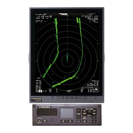
Features The FR-1908V-BB/FR-1918V-BB consists of an antenna unit, processor unit, and control unit and is designed to meet the requirements of navigation radar used on inland waterways. Radar targets are displayed on a vertically oriented SXGA display, in a single color or gradations of green or cyan according to echo strength. -
Page 11: System Configuration
SYSTEM CONFIGURATION Radiator ANTENNA UNIT XN20AF (6.5 ft) XN24AF (9 ft) - RSB-120-102 (4kW, FR-1908V-BB) - RSB-120-124 (12kW, FR-1918V-BB) Control Unit RW-0013 RCU-032 External Monitor (e.g. MU-190V) - ROT Sensor (Analog/Alarm) - Auto Pilot 24 VDC (Analog/Follow-up) - Rudder (Analog) - Page 12 SYSTEM CONFIGURATION This page is intentionally left blank.
-
Page 13: Controls
OPERATION Controls Power lamp Touch pad Setting knob PUSH TO SELECT BRILL MENU RANGE ADJUST CENTER STBY Left button Right button Power key Control Function Power key Turn On/Off power. Power lamp lights when the power is turned on. STBY/TX Switch between stand-by and transmission. -
Page 14: How To Transmit
1. OPERATION How to Transmit To transmit, press the STBY/TX key while [STBY] is displayed. Radar echoes are dis- played on the screen with the previously used settings of range. Each press of the STBY/TX key switches between stand-by and transmit (You can also switch between stand-by and transmission by clicking the [STBY/TX] indication.). - Page 15 1. OPERATION Icon/Symbol Icon/Symbol Operation mode ROT/Rudder graph Range/Range ring interval Orientation mode Standby/Transmit Off-center Generated alarm Alarm acknowledge Heading Pulse width Own ship position (Lat/Lon) Capture Ship speed Depth Time to go to cursor posi- Cursor position tion Menu Wind speed or Date/Time* Barge Mark Mark...
-
Page 16: Menu Operation
1. OPERATION Menu Operation 1.5.1 How to operate the radar from the icons How to select the menu icon on the screen Use the touch pad to select an icon. The icon is highlighted when correctly selected. Put the cursor on an icon HEAD-UP ►... -
Page 17: Menu Window
1. OPERATION Mouse operation A mouse can be connected to the processor unit to control radar functions. The table below compares operation with the control unit and mouse. Note: Connect the USB mouse to the processor unit directly. Do not use a USB hub when connecting the USB mouse to the processor unit. -
Page 18: List Windows
1. OPERATION 1.5.4 List windows There are three list windows (TT, AIS and Alarm) and they provide information about tracking targets, AIS targets and generated alarms. • TT list: Click the [LIST] icon for TT at the bottom of the display to show the TT list. [TT LIST] RANGE BEARING... -
Page 19: Panel Dimmer
1. OPERATION 1. Click the setting box for display brilliance at the bottom left corner of the screen. 2. Press the left button to decrease the brilliance; the right button to increase the bril- liance. With mouse connection, rotate the wheel or click the right or left button to adjust the brilliance. - Page 20 1. OPERATION How to select a customized brilliance set 1. Click the [BRL] icon at the bottom left corner on the screen to show the [BRILL MENU] window. [BRILL MENU] BACK MARK MARK Click USER-NAME1 USER-NAME3 BRL1-1/ BRL3-1/ BRL1-2/ BRL3-2/ BRL2-3 BRL2-3 BRL1-3/...
-
Page 21: Color Scheme
1. OPERATION Color Scheme You can select the color for echo and background MARK color (inside/outside) with the display icons. BRL2-3 BRL2-3 ECHO Click the icon to B-IN change the color. D-GRN MONI PANL Available colors Available options (Each color is selectable respectively) [ECHO COLOR] M-GRN* M-CYA*... - Page 22 1. OPERATION Default settings for [USER 1] to [USER 4] Available options (Each color is selectable) [USER 1] [USER 2] [USER 3] [USER 4] [ECHO COLOR] GRN (green) WHT (white) GRN (green) [BACK COLOR (INSIDE)] BLK (black) [BACK COLOR (OUTSIDE)] BLK (black) D-BLU D-GRY...
-
Page 23: Tuning
1. OPERATION Tuning 1.8.1 How to select the tuning method The tuning method, auto tuning or manual tuning, can be selected with the tuning icon as follows. Click the tuning icon ([AUTO] or [MAN]) at the bottom right corner on the screen to switch between [AUTO] and [MAN]. -
Page 24: Echo Area
1. OPERATION Echo Area The echo display area can be selected for [CIRCLE] or [WIDE], in the [SEA] mode. 1. Open [MAIN MENU], click [DISPLAY]. 2. Click [ECHO AREA] then select the op- Gray zone: Echo area tion. [CIRCLE]: Echoes in the radar circle. [WIDE]: Echoes in the whole of the dis- play 3. -
Page 25: Orientation Mode
1. OPERATION 1.10.2 Orientation mode Relative motion (RM) In relative motion, own ship position is stationary on the screen to observe relative mo- tion of surrounding targets. • HEAD UP The head-up mode is a display in which the line Heading North marker connecting own ship and the top of the display... -
Page 26: How To Select An Orientation Mode
1. OPERATION True motion (TM) • NORTH UP Ground (or water mass) is stabilized with compass and speed inputs. Your ship and other objects in motion move with their true courses and speed. • COURSE UP Own ship and other moving objects move in North mark accordance with their true courses and speed. -
Page 27: How To Change Orientation Mode Presets
1. OPERATION 1.10.4 How to change orientation mode presets Seven orientation modes are available in [SEA] mode, two orientation modes in the [RIVER] mode. You can remove unnecessary modes from the Orientation icon as fol- lows. 1. Right-click the orientation icon to show the [ORIENTATION MODE] window. [ORIENTATION MODE] RUDDER BACK... - Page 28 1. OPERATION Range for River mode In River mode, the default unit is SM. Range (SM) Range ring interval (SM) 0.125 0.025 0.25 0.05 Range for Sea mode In Sea mode, the default unit is NM. Range (NM) Range ring interval (NM) 0.125 0.025 0.25...
-
Page 29: Pulse Width
1. OPERATION 1.12 Pulse width The pulse width in use is displayed at the top left corner on the screen. The pulse widths are set to each range scale and custom setup. Use a longer pulse width when your purpose is long range detection. Use a shorter pulse width when the resolution is important. -
Page 30: How To Select A Pulse Width
1. OPERATION 1.12.2 How to select a pulse width 1. Right-click [CUSTOM] icon at the bottom right corner on the screen to show [CUSTOM MENU]. [CUSTOM MENU] BACK Right-click [EDIT] CUSTOM1-1 CUSTOM1-1 ► ► [PRESET] FTC 1 TRAIL ► 2. Click [EDIT]. [EDIT] BACK USER NAME... -
Page 31: How To Reduce The Sea Clutter
1. OPERATION 1.14 How to Reduce the Sea Clutter The reflected echoes from the waves appear around your ship and are called “sea clutter”. The sea clutter extends according to the height of waves and antenna above the water. When the sea clutter hides the tar- gets, reduce the clutter, either manu- ally or automatically. -
Page 32: How To Reduce The Rain Clutter
1. OPERATION 1.15 How to Reduce the Rain Clutter The reflections from the rain or snow appear on the screen. These reflected echoes are called “rain clutter”. When the rain clutter is strong, targets in the rain clutter are hidden in the clutter. Reflections from the rain clutter are easily identified from true tar- gets by their wool-like appearance. -
Page 33: Ftc (Fast Time Constant)
1. OPERATION 1.17 FTC (Fast Time Constant) If you can not effectively suppress rain CAUTION clutter with the rain clutter control, use the FTC function. In adverse weather, clouds, Switch off FTC if your objective is to rain or snow produce spray-like spurious receive a radar beacon signal. -
Page 34: How To Measure The Bearing To A Target (Ebl)
1. OPERATION 1. Click the [VRM] icon to display the VRM. If the VRM is already shown, go to step 2. 2. Click the [VRM] icon. The icon turns yellow. AUTO T AUTO T ► Click LIST ► ► LIST ►... -
Page 35: Offset Ebl
1. OPERATION 1.20 Offset EBL How to offset an EBL You can move the EBL origin to a desired location as follows: 1. Put the cursor on the appropriate [EBL] icon to activate the EBL. The mark (>), which denotes active EBL, moves to the [EBL] icon selected. The example below shows how to activate the EBL1. - Page 36 1. OPERATION 8. Click the center of the target B. The EBL bi- EBL1 EBL1 sects target B. Target B Target B Target A Target A EBL origin 9. Click the [VRM1] icon to change the Click range. The [VRM1] icon turns yellow. 0.550NM 0.550NM VRM1...
-
Page 37: Collision Assessment By Offset Ebl
1. OPERATION 1.20.2 Collision assessment by offset EBL The origin of the EBL can be moved to enable measurement of range and bearing be- tween any targets. This function is also useful for assessment of the potential risk of collision. 1. -
Page 38: Point Of Reference For Origin Point Of Offset Ebl
1. OPERATION 1.20.3 Point of reference for origin point of offset EBL The origin point of the offset EBL can be ground stabilized (geographically fixed), north stabilized (true) or referenced to own ship’s heading (relative). This menu is available in [SEA] mode only. However, the setting is applied in [RIVER] mode also. 1. -
Page 39: How To Off-Center The Display
1. OPERATION 1.21 How to Off-center the Display Own ship position, or sweep origin, can be moved to expand your field of view without switching to a larger range scale. The sweep origin can be off-centered to the cursor position, but not more than 60% of the range in use; if the cursor is set beyond 60% of the range scale, the sweep origin will be off-centered to the point of 60% of the limit. -
Page 40: Interference Rejecter
1. OPERATION 1.22 Interference Rejecter The radar interference can occur when your ship is near the radar of another ship that operates on the same frequency band with your radar. The interference appears on the screen as many bright dots. The dots can be random or in the shape of dotted lines that run from the center to the edge of the display. -
Page 41: Echo Averaging
1. OPERATION 1.24 Echo Averaging To identify true target echoes from sea clutter, echoes are averaged over successive picture frames. If an echo is solid and stable, the echo is shown in its normal intensity. The brilliance of sea clutter is reduced to easily identify true targets from the sea clut- ter. -
Page 42: Trail] Menu
1. OPERATION 1.25.2 [TRAIL] menu You can adjust the detail setting for trails on the [TRAIL] menu. 1. Right-click the [TRAIL] icon to show the [TRAIL] menu. [TRAIL] FTC 1 BACK Right- TRAIL MODE TRAIL click REL /TRUE 2.50sec TRAIL LEVEL 1 /2/3/4 EAV 3 00m03s... -
Page 43: Trail Level
1. OPERATION 1.25.4 Trail level The level (intensity) of the afterglow that extends from radar targets may be selected as below. 1. Right-click the trail icon to show the [TRAIL] menu. 2. Click [TRAIL LEVEL]. 3. Select the trail level among 1 to 4. The higher the number the greater the intensity of the afterglow. -
Page 44: Trail Color Modes
1. OPERATION 1.25.7 Trail color modes There are two color modes for the trail color, [DEFAULT] and [USER]. • [DEFAULT]: The trail color becomes the same color as the echo color. • [USER]: The trail color is set on [TRAIL COLOR] in [BRILL MENU]. See "How to edit [BRILL MENU]"... -
Page 45: How To Select The Alarm Type
1. OPERATION 3. Use the touch pad to select the point "B" then push the left button. [IN] (or [OUT]) replaces [SET] in the [ALR] icon. The target alarm zone’s lines are shown in dashed lines. ALR1 IN ALR1 IN LIST ALR1 OUT ALR1 OUT... -
Page 46: How To Select The Target Strength Which Triggers A Target Alarm
1. OPERATION 1.26.3 How to select the target strength which triggers a target alarm You can select the target strength which triggers the target alarm as follows. 1. Open [MAIN MENU], click [ALARM]. 2. Click [TARGET ALARM]. 3. Click [LEVEL]. 4. -
Page 47: Nav Lines
1. OPERATION 1.27 NAV Lines There are two NAV lines for port and starboard. NAV LINE for port NAV LINE for starboard How to display the NAV lines Click the appropriate [NAV] icon at the bottom of the screen. MENU CUSTOM3-4 FTC 1 TRAIL... -
Page 48: Alarms, Error Messages
1. OPERATION 1.28 Alarms, Error Messages 1.28.1 Alarm indication When the alarm is generated, the [ALARM] icon flashes (in red) and the audio alarm sounds. [ALARM] icon RIVER RUDDER ALARM 1.2/ 0.5 ALARM HEAD-UP HDG 123.4° [ALARM ACK] icon OFFCENT (at the top left corner STBY on the screen) -
Page 49: Alarm Description
1. OPERATION 1.28.2 Alarm description Alarm description Alarm type Alarm message Meaning COLLISION TT DANGEROUS CPA and TCPA of a TT is within a preset limit. ALARM AIS DANGEROUS CPA and TCPA of an AIS target is within a preset limit. -
Page 50: Alarm Summary
1. OPERATION 1.28.3 Alarm summary When an alarm is generated the color of the [ALARM] icon (top of display) turns red. You can see what alarms have been generated in the [ALARM SUMMARY] menu. 1. Right-click the [ALARM] icon to show the [ALARM] menu. RIVER Right- [ALARM]... -
Page 51: Depth Alarm
1. OPERATION 1.28.5 Depth alarm The depth alarm warns you when the depth is shallower than the preset depth value. To change the depth, follow the steps below. 1. Open [MAIN MENU], click [NAV DATA]. 2. Click [DEPTH]. 3. Click [DEPTH ALARM VALUE] then set the value by rotating the setting knob. The setting range is 0.00 to 9.99 m. -
Page 52: How To Activate The Docking Mode
1. OPERATION 1.29.1 How to activate the docking mode The docking mode can be shown in TX mode. 1. Open [MAIN MENU], click [DISPLAY]. 2. Click [DOCKING MODE]. 3. Click [ON] to display the docking icon at the minimum range among the available ranges. -
Page 53: Depth Data
1. OPERATION 1.29.4 Depth data Depth at the fore and aft are shown with the docking information display. This feature requires fore and aft depth data. Note: Dual depth requires two transducers. 10.4 Front Depth at fore 13.7 Depth at aft 1 min [NUMERICAL] data display [GRAPHICAL] data display... -
Page 54: Depth Graph
1. OPERATION 1.29.5 Depth graph You can see the depth data in graph format by setting [GRAPH TYPE] to [GRAPHI- CAL] (see step 3 in "Depth display format" on page 1-41). The depth graph shows the depth history with dots, not a line. Depth at front sensor (white) Depth... -
Page 55: How To Predict Own Ship's Position
1. OPERATION 5. Click outside the menu window to close the menu. Speed and movement indications and orientation mode The stern mode shows aft speed on top. Stern up mode Head up mode FRONT FRONT 1.30 How to Predict Own Ship’s Position You can predict ship’s position in the vector time selected. -
Page 56: How To Program Function Keys (F1 And F2)
1. OPERATION 1.31 How to Program Function Keys (F1 and F2) You can program function keys (F1 and F2) to provide one-touch access to a required function. To activate a function, press the applicable function key, F1 or F2. The default settings for the F1 and F2 keys are [ORIENTATION MODE] and [DOCK- ING] respectively. - Page 57 1. OPERATION • Options available in the [OPERATION] menu [F1-OPERATION] BACK ECHO COLOR/ MARK/LINE-ON/* MONITOR BRILL/ BARGE-ON/* *: [RIVER] mode only PANEL DIMMER/ MAP ALIGN/* TRANSPARENCY/ MARK/LINE ALL DELETE/* **: [SEA] mode only ALARM1/** BARGE ALL DELETE* ALARM2/** ECHO AREA/** DOCKING/ •...
-
Page 58: Markers
1. OPERATION 1.32 Markers 1.32.1 [MARK] menu The [MARK] menu lets you: • Change the configuration of the own ship mark • Show or hide the stern mark • Set the reference point for the offset EBL • Activate VRM with the offset EBL 1. -
Page 59: Stern Mark
1. OPERATION 1.32.3 Stern mark The stern marker, which is a dot-and-dash line, appears opposite to the heading line. To display or erase this marker do the following: 1. Open the [MARK] menu, click [STERN MARK]. 2. Click [OFF] or [ON] as appropriate. 3. -
Page 60: Barge Mark
1. OPERATION 1.32.6 Barge mark You may mark the locations of barges on the display with barge mark. This function is available for [RIVER] mode only. Barge mark Barge mark Own ship The barge mark is a set of rectangles drawn to indicate the outline of barges. You can create a max. - Page 61 1. OPERATION How to create a barge mark on the screen 1. Click the barge number icon then rotate the setting knob to select the barge num- ber (1 to 10). MENU BARGE ON MARK MARK DOCK OFF BRL2-3 ECHO B IN 2.
- Page 62 1. OPERATION How to create a barge mark from the [BARGE ICON] menu 1. Right-click the any icon of barge mark to show the [BARGE NUMBER] menu. [BARGE NUMBER 2] MENU BACK Click any icon POSITION BY X BARGE BARGE X = +0000ft POSITION BY Y MARK...
-
Page 63: Nav Data
1. OPERATION How to delete barge marks by color 1. Open [MAIN MENU], click [RADAR MAP]. [RADAR MAP] BACK MAP ALIGN OFF/ON [MARK/LINE INFO] [DATA DELETE] 2. Click [DATA DELETE]. [DATA DELETE] BACK [MARK/LINE DELETE] [BARGE DELETE] 3. Click [BARGE DELETE]. [BARGE DELETE] BACK COLOR... - Page 64 1. OPERATION Speed menu Right-click the speed icon ([SPD]) to show [SPEED MENU]. [SPEED MENU] ±300 °/min Right- BACK ±180 ° SELECT DUAL SENSOR MANUAL SPEED click CAPT SPD BT GPS-F SPD BT GPS-F 44. 6km/h ► ► FRONT/AFT 0. 0kn DPT AFT 3.
-
Page 65: How To Show Wind Data Or Date Alternately
1. OPERATION 1.33.2 How to show wind data or date alternately Click the icon shown below to show wind data or date alternately. (at the top right corner on the screen) ±300°/min ±300°/min ±180° ±180° Click CAPT OS POSN N 0°... -
Page 66: Time To The Cursor Position
1. OPERATION 1.33.3 Time to the cursor position The time from own ship to the cursor posi- ±300º/min tion (TTG: time-to-go) is shown at the top ±180º CAPT OS POSN N 0° 00. 219° right corner on the screen. 0° 00. 397° ►... -
Page 67: Customized Menus
1. OPERATION Autopilot graph 1) Follow-up (FU) mode When the autopilot is in the follow-up mode, the follow-up rudder command is in- dicated on the RUDDER scale. In addition, "FOLLOW UP" is indicated at the top of the screen. In follow-up mode, the autopilot controls the rudder so that actual rudder angle becomes same as commanded one. - Page 68 1. OPERATION How to edit the [CUSTOM MENU] Note: The [CUSTOM1-1] setting is fixed as a default setting. You can edit the setting, but when the system is turned off, the default setting are restored. To save a custom- ized set, select a setting other than [CUSTOM1-1]. 1.
-
Page 69: Sd Cards
1. OPERATION 7. Click the menu to set in the [EDIT] menu. [EDIT] BACK USER NAME ECHO AVERAGE 14 [PULSE WIDTH (RIVER)] USER NAME 1 OFF/1/2/3 USER COMMENT WIPER 16 SAVE & QUIT CUSTOM4-4 OFF/ON [GAIN/STC/RAIN] 10 VIDEO CONTRAST TYPE A/B/C/D OFF/1/2 11 [STC CURVE]... -
Page 70: How To Save And Replay The Data
All SD card operations begin from the [FILES] menu. [FILES] The [FILES] menu is available in stand-by mode. BACK DRIVE SELECT The data witch is saved in the FR-1908V-BB/FR- SD-1 /SD-2 [DRIVE INFO] 1918V-BB do not have the compatibility with other [SAVE DATA] [REPLAY (READ) DATA] models. -
Page 71: How To Set Menu And Icon Behavior
1. OPERATION • [SAVE DATA]: Save the file stored on the following file group set at [NAME]. Set the name with the software keyboard. Click the [END] key to complete the name setting. [MARK/LINE]* (see the figure shown right) [MARK/LINE] [SETTING DATA] BACK NAME... -
Page 72: Icons
1. OPERATION 1.36.2 Icons You can show or hide some labels and auto hide them after the specified period elapsed. How to select the menu icons to display 1. Open [MAIN MENU], click [DISPLAY]. 2. Click [HIDDEN ICON]. [HIDDEN ICON] BACK NAV DATA 10 ECHO... -
Page 73: Other Features
1. OPERATION 1.37 Other Features 1.37.1 Guidance box (Help function) The Guidance box provides operating guidance for a cursor-selected item. You can show or hide the guidance as follows: (at the bottom of the screen) OPEN AIS LIST AIS/LIST MENU Function with Function with LIST... -
Page 74: Display Capture
1. OPERATION 1.37.3 Display capture You can capture the screen shots to replay them on [CAPTURE] the PC. The setting for the display capture is set on the [CAPTURE] menu. To open the [CAPTURE] BACK DRIVE SELECT menu, open [MAIN MENU] then click [CAPTURE]. SD-1 /SD-2 [DRIVE INFO] The [CAPTURE] menu is available in the stand-by... - Page 75 1. OPERATION [CAPTURE] menu items • [DRIVE SELECT]: Click the drive [SD-1] or [SD-2] to use. The [SD-1] is upper slot and [SD-2] is lower. • [DRIVE INFO]: Confirm the number of screen shots saved and the remaining ca- pacity of the SD card selected at [DRIVE SELECT]. [DRIVE INFO] [NORMAL]: Auto captured files at the specified BACK...
-
Page 76: How To Customize The Operation
1. OPERATION 1.37.4 How to customize the operation You can customize the operation [OPERATION] on the [OPERATION] menu. BACK Open [MAIN MENU], click REF POINT GUIDANCE [CONFIGURATION]. Then click ANT /CCRP OFF /ON KEY BEEP [TOUCH-PAD] [OPERATION] to open the [OP- OFF /LOW/MID/HIGH [POINTING-DEVICE] ERATION] menu. -
Page 77: Transmit Time
1. OPERATION 1.37.5 Transmit time ON time, TX time and TRON time are shown on the stand-by display. You can also show these values by using the Transmit icon. 1. Right-Click the transmit icon ([TX] or [STBY]) to open the [TX STBY] menu. [TX STBY] BACK RUDDER... - Page 78 1. OPERATION This page is intentionally left blank. 1-66...
-
Page 79: Target Tracking (Tt)
TARGET TRACKING (TT) The Target Tracking function requires the heading data and ship’s speed data. TT Display On/Off To show or hide the TT display, click the [TT] icon at the bottom left corner on the screen. [TT OFF]: Deactivates TT. [TT ON]: Activates TT. - Page 80 2. TARGET TRACKING (TT) TT symbols Symbol Status Remarks Automatically Initial stage Broken circles enclose an echo to indicate acquired the target under acquisition and initial stage targets of tracking, before steady-state tracking Within one minute after acquisition (vector still unreliable). Steady tracking Solid circle with vector indicating steady state tracking (within three minutes after ac-...
-
Page 81: How To Acquire And Track Targets
2. TARGET TRACKING (TT) How to Acquire and Track Targets This radar can acquire a maximum of 100 targets, the number of automatically and manually acquired targets determined by the [TT TARGET MENU] setting. 1. Right-click the [TT] icon to show the [TT TARGET MENU] window. [TT TARGET MENU] BACK TT SELECT... -
Page 82: Automatic Acquisition
2. TARGET TRACKING (TT) Automatic Acquisition Targets which enter an acquisition zone (two zones possible) are automatically ac- quired. Set an acquisition area as follows: 2.4.1 How to set an acquisition zone Note: The acquisition zone can not be set within 3 NM from own ship. 1. -
Page 83: Acquisition Zone Reference
2. TARGET TRACKING (TT) 2.4.4 Acquisition zone reference 1. Open [MAIN MENU], click [TT AIS]. 2. Click [ACQUIRE ZONE]. [ACQUIRE ZONE] BACK AZ STAB STAB NORTH/ STAB HEADING POLYGON STAB OFF/STAB GND/ STAB NORTH/ STAB HEADING 3. Click [AZ STAB] then the acquisition zone reference as appropriate. -
Page 84: Tt Symbol Attributes
2. TARGET TRACKING (TT) 4. Click outside the menu window to close the menu. TT Symbol Attributes 2.6.1 TT symbol brilliance 1. Right-click the [BRL] icon to show the [BRILL MENU] window. [BRILL MENU] BRL 2-3 ► ► BACK [EDIT] ECHO ►... -
Page 85: Lost Target
2. TARGET TRACKING (TT) 6. Click outside the menu window to close the menu. Lost Target Targets not detected in five consecutive scans become "lost targets." A lost target is shown in the display with a flashing red "X". Flashing stops after the lost target (flashing) alarm is acknowledged. -
Page 86: Tt Data
2. TARGET TRACKING (TT) 2.7.2 How to acknowledge a lost target 1. Right-click the [TT] icon to show [TT TARGET MENU]. 2. Click [ACK LOST TARGETS]. 3. Click [YES]. All lost targets disappear from the screen. TT Data The TT target list provides a comprehensive data display of all TT targets being tracked. -
Page 87: Tt List
2. TARGET TRACKING (TT) TT List How to display the TT list The TT list provides the range, bearing, CPA and TCPA of all tracking targets. To display the TT list, click the [LIST] icon for TT at the bottom left corner on the screen to show the [TT LIST] window. -
Page 88: Vector Modes
2. TARGET TRACKING (TT) 2.10 Vector Modes Target vectors can be displayed relative to own ship's heading (Relative) or north (True). 2.10.1 Description of vectors Sea stabilization is a mode where own ship and all targets are referenced to the sea using a compass heading and single-axis log water speed inputs. -
Page 89: Past Position Display
2. TARGET TRACKING (TT) 2.11 Past Position Display Equally time-spaced dots shows the past position display marking the past positions of any targets being tracked. A new dot is added every minute (or at other preset time intervals) until the preset number is reached. -
Page 90: Cpa/Tcpa Alarm
2. TARGET TRACKING (TT) 2.12 CPA/TCPA Alarm The CPA/TCPA alarm alerts you when both the CPA and TCPA of a TT is within a de- fined limit. CPA and TCPA of the target is less than the alarm settings. 1. Open [MAIN MENU], click [ALARM]. 2. -
Page 91: Ais Operation
AIS OPERATION The AIS (Automatic Identification System) transponder connected to this radar ex- changes all data and information required by the SOLAS 1994 with other AIS-fitted ships. AIS information is graphically indicated together with the radar and TT informa- tion. When AIS is active, manual or reference speed selection is not available. - Page 92 3. AIS OPERATION AIS symbols Symbol Status Remarks Sleeping target Smaller triangle than an active target Activated target Heading line, ship speed/course vectors are dis- played. Color is selectable on the menu. Turning target A turning symbol is displayed. Dangerous target Collision alarm symbol is displayed in red.
-
Page 93: Ais Display Filter
3. AIS OPERATION AIS symbols with Blue sign, Blue cones Blue Not connected or Not set sign not available number 1 to 3 1 to 3 1 to 3 (Red mark) (Red mark) (Red mark) Blue cones With heading (Scaled symbol) (Scaled symbol) (Scaled symbol) (Scaled symbol) -
Page 94: How To Activate Targets
3. AIS OPERATION 3. Set item 3 to 13 referring to the description below. [CLASS A]: Hide or show the CLASS A AIS targets. [CLASS B]: Hide or show the CLASS B AIS targets. [BASE STATION]: Hide or show AIS base stations. [MIN RANGE], [MIN RANGE VALUE]: If [MIN RANGE] is set to [ON], only AIS tar- gets further than the range set at [MIN RANGE VALUE] are shown. -
Page 95: How To Sleep Targets
3. AIS OPERATION How to Sleep Targets 3.4.1 How to sleep an individual target You may “sleep” an AIS target as below when the screen becomes filled with targets, which might prevent important radar and AIS displays from being identified. Note that targets that have been activated automatically cannot be “slept”. -
Page 96: Past Position Display
3. AIS OPERATION 3. Click [AIS] to show the [AIS] window. [AIS] BACK SYMBOL COLOR GRN/BLU/CYA/MAG/WHT ROT TAG LIMIT 000.1deg/min SCALED SYMBOL 4. Click [SYMBOL COLOR] then the desired color. OFF/ON 5. Click [SCALED SYMBOL]. 6. Click [OFF] or [ON] as appropriate. [OFF]: All AIS symbols shown in same size. -
Page 97: Lost Target
3. AIS OPERATION Lost Target When AIS data is not received from a target within 3-5 report intervals (see Note 2), the target symbol changes to the lost target symbol (flashing). No audio or visual alarm is given for a lost target. Activated target Lost target Note: The AIS data transmission interval depends on target’s speed. -
Page 98: Rot Setting
3. AIS OPERATION 3. Click [YES]. The lost target disappears from the screen. ROT Setting You may set the lower limit of the ROT (Rate Of Turn) at which the heading line on target symbols points the ship’s turning direction. 1. -
Page 99: Automatic Target Activation
3. AIS OPERATION 3.10 Automatic Target Activation You can get automatic activation of a sleeping AIS target when its CPA is within the CPA/TCPA alarm setting. Further, you can select which AIS targets to automatically activate. 1. Right-click the [AIS] icon to show the [AIS TARGET MENU] window. 2. -
Page 100: Ais Target Data
3. AIS OPERATION 3.11 AIS Target Data You may display an AIS target’s data by selecting it on the display. This data is shown for the activated AIS target only. The selected AIS target is enclosed in a broken square. The target data is shown on the [AIS INFO] window. Selected AIS to display the information [AIS INFO]... -
Page 101: Ais List
3. AIS OPERATION 3.12 AIS List The AIS list provides a comprehensive information about all AIS targets being tracked. How to display the AIS list Click the [LIST] icon for AIS at the bottom right corner on the screen. [LIST] icon for AIS [LIST] icon for AIS 01m0 [AIS LIST] <SORT>NAME-UP... - Page 102 3. AIS OPERATION This page is intentionally left blank. 3-12...
-
Page 103: Radar Map
RADAR MAP What is a Radar Map? The radar map feature, available in the [RIVER] mode, is a combination of map lines and symbols whereby the user can define and input the navigation, route planning and monitoring data on the screen. Map lines are a navigational facility whereby the ob- server can define lines to indicate channels or traffic separation schemes. -
Page 104: How To Enter Marks, Lines
4. RADAR MAP How to Enter Marks, Lines 4.3.1 How to enter a mark, line with at the cursor position 1. Click the mark color icon to select the re- MENU quired color for the mark. BARGE ON Mark color icon MARK MARK BRL2-3... -
Page 105: How To Enter A Mark By Latitude And Longitude Position Input
4. RADAR MAP 4.3.2 How to enter a mark by latitude and longitude position input This function is not available for entering lines. 1. Right-click the [MARK] icon to show the [MARK ICON] [MARK ICON] window. BACK [CREATE] OWN SHIP 2. -
Page 106: How To Show, Hide Marks On The Screen
4. RADAR MAP How to Show, Hide Marks on the Screen By menu icon Click the mark display icon to show or hide the marks. MENU MENU BARGE ON BARGE ON MARK MARK Click MARK MARK DOCK OFF DOCK OFF BRL2-3 BRL2-3 ECHO... -
Page 107: How To Align The Radar Map
4. RADAR MAP 3. Click [MARK/LINE DELETE]. [MARK/LINE DELETE] BACK [SHAPE DELETE] [COLOR DELETE] MARK/LINE ALL DELETE NO/YES 4. Click the sort to delete. [SHAPE DELETE]: Select the shape to delete then select [YES] in [DELETE]. [COLOR DELETE]: Select the color to delete then select [YES] in [DELETE]. 5. - Page 108 4. RADAR MAP This page is intentionally left blank.
-
Page 109: Maintenance, Troubleshooting
MAINTENANCE, TROUBLE- SHOOTING WARNING NOTICE Do not apply paint, anti-corrosive Do not open the equipment. sealant or contact spray to coating or plastic parts of the equipment. Hazardous voltage which can cause electrical shock exists Those items contain organic solvents that inside the equipment. -
Page 110: Preventive Maintenance
5. MAINTENANCE, TROUBLESHOOTING Preventive Maintenance Regular maintenance helps keep your equipment in good condition and prevents fu- ture problems. Check the items shown on next page to help keep your equipment in good condition for years to come. Ground terminal on processor units Tighten or replace as necessary. -
Page 111: Life Expectancy Of Major Parts
This radar has consumable parts, and the table that follows shows the estimated life expectancy for the consumable parts. Life expectancy estimates are based on use un- der normal conditions. Request a FURUNO agent or dealer to replace the consumable parts, to get the best performance and longest possible life from the equipment. -
Page 112: Nmea Sentences Checks
5. MAINTENANCE, TROUBLESHOOTING Example of the Self Test result 1. Open [MAIN MENU], click [CONFIGURATION]. 2. Click [TEST]. 3. Click [SELF TEST]. Test results of processor unit and control unit are displayed. Items 8 to 11, 15 and 16 are displayed [OK] if normal and [NG] if abnormal. When [NG] is displayed, request a service. -
Page 113: Easy Troubleshooting
5. MAINTENANCE, TROUBLESHOOTING Easy Troubleshooting This section provides troubleshooting procedures that the user may follow to restore normal operation. If you cannot restore normal operation, do not attempt to check in- side any unit. Leave any repair work to a qualified technician. Easy troubleshooting Problem Remedy... -
Page 114: Advanced Troubleshooting
5. MAINTENANCE, TROUBLESHOOTING Advanced Troubleshooting This section describes how to cure hardware and software troubles that should be car- ried out by qualified service personnel. Advanced troubleshooting Probable causes or Problem Remedy check points You cannot turn on the • Blown fuse. •... -
Page 115: Appendix 1 Radio Regulatory Information
This equipment complies with ISED radiation exposure limits set forth for an uncontrolled environment and meets RSS-102 of the ISED radio frequency (RF) Exposure rules. This equipment should be installed and operated keeping the radiator at least 50 cm (FR-1908V-BB) , 340 cm (FR-1918V-BB) or more away from person's body. -
Page 116: Appendix 2 Menu Tree
APPENDIX 2 MENU TREE MAIN MENU MAIN MENU 1 BACK* 2 ECHO 1 BACK *: [SEA] mode only 2 TUNE INITIALIZE ***: [RIVER] mode only 3 STC PRESET (OFF, ON) 4 FTC PRESET (OFF, ON) 3 DISPLAY 1 BACK 2 TRANSPARENCY (OFF, ON) 3 DOCKING MODE (OFF, ON) 4 OWN SHIP MARK (OFF, ON) 1 BACK... - Page 117 APPENDIX 2 MENU TREE (FROM PREVIOUS PAGE) *: [SEA] mode only 7 NAV DATA ***: [RIVER] mode only 1 BACK 2 PREDICTION 1 BACK 2 OWN SHIP POSITION (DUAL-GPS, SC) 3 DEPTH 1 BACK 2 GRAPH TYPE (NUMERICAL, GRAPHICAL) 3 DUAL SENSOR (BOTH, FRONT, AFT) 4 DEPTH SCALE 1 BACK 2 SCALE TYPE...
- Page 118 APPENDIX 2 MENU TREE (FROM PREVIOUS PAGE) 10 CONFIGURATION 1 BACK 1 BACK 2 OPERATION 2 REF POINT (ANT, CCRP) 3 KEY BEEP (OFF, LOW, MID, HIGH) 4 OWN SHIP VECTOR (OFF, COURSE, HDG) 5 CURSOR SIZE (SMALL, LARGE) 6 GUIDANCE (OFF, ON) 7 TOUCH PAD 1 BACK 2 TOUCH-PAD (OFF, ON)
- Page 119 APPENDIX 2 MENU TREE (FROM PREVIOUS PAGE) 1 BACK 4 TEST 2 SELF TEST 1 BACK 3 SENTENCE MONITOR 2 NMEA1 3 NMEA2 4 NMEA3 5 NMEA4 6 NMEA5 7 NMEA6 *: [SEA] mode only 11 ALARM 1 BACK 1 BACK 2 TT•AIS (Protected as 1 BACK...
-
Page 120: Appendix 3 Digital Interface (Iec61162-1
APPENDIX 3 DIGITAL INTERFACE (IEC61162-1) Input sentences ALR : Set alarm state $**ALR,Hhmmss.ss,xxx,A,A,c—c,*hh<CR><LF> 2 3 4 1. Time of alarm condition change, UTC (000000.00 - 240001.00) 2. Unique alarm number (identifier) at alarm source (000 - 999) 3. Alarm condition (A=threshold exceeded, V=not exceeded) 4. - Page 121 APPENDIX 3 DIGITAL INTERFACE (IEC61162-1) GBS : GNSS satellite fault detection $**GBS, hhmmss.ss, x.x, x.x, x.x, xx, x.x, x.x, x.x *hh<CR><LF> 1. UTC time of GGA or GNS fix associated with this sentence 2. Expected error in latitude (0.0 - 999.9) 3.
- Page 122 APPENDIX 3 DIGITAL INTERFACE (IEC61162-1) HDT : Heading True $**HDT, xxx.x,T*hh<CR><LF> 1. Heading, degrees (0.00 to 360.00) 2. True (T) HTD : Heading/Track control data $**HTD,A,x.x,a,a,a,x.x,x.x,x.x,x.x,x.x,x.x,x.x,a,A,A,A,x.x*hh<CR><LF> 2 3 4 5 6 8 9 10 11 12 13 141516 17 1. Override, A = in use, V = not in use 2.
- Page 123 APPENDIX 3 DIGITAL INTERFACE (IEC61162-1) ROT : Rate of Turn $GPROT,x.x,A*hh<CR><LF> 1. Rate of turn, deg/min, "-"=bow turns to port (-9999.9 - 9999.9) 2. Status: A=data valid, V=data invalid RSA : Rudder Sensor Angle $**RSA,x.x,A,x.x,A*hhCR><LF> 1 2 3 4 1. Starboard(or single) rudder sensor data (-180 - 180.0, NULL) 2.
- Page 124 APPENDIX 3 DIGITAL INTERFACE (IEC61162-1) VTG : Course over ground and ground speed $GPVTG,x.x,T,x.x,M,x.x,N,x.x,K,a,*hh <CR><LF> 1 2 3 4 5 6 7 8 9 1. Course over ground, degrees (0.0 - 359.9) 2. T=True (fixed) 3. Course over ground, degrees (0.0 - 359.9) 4.
- Page 125 APPENDIX 3 DIGITAL INTERFACE (IEC61162-1) Output sentences TTM : Tracked target message $RATTM,05,12.34,23.4,R,45.67,123.4,T,1.23,8.23,N,c--c,T,R,hhmmss.ss,M*hh<CR><LF> 9 10 11 12 13 1. Target number (00 to 99) 2. Target distance from own ship (0.000 - 999.9) 3. Bearing from own ship,degrees (0.0 - 359.9) 4.
-
Page 126: Specifications
FR-1908V-BB/1918V-BB SPECIFICATIONS OF RIVER RADAR FR-1908V-BB/1918V-BB ANTENNA UNIT Radiator type Slotted waveguide array Polarization Horizontal Antenna rotation speed 26 rpm nominal Radiator length 6.5 ft (XN20AF), 8 ft (XN24AF) Horizontal beam width -3dB 1.23° (XN20AF) 0.95° (XN24AF) -20dB 2.84° (XN20AF), 2.5° (XN24AF) Vertical beam width 20°... - Page 127 Number of rings 6 4 6 4 6 Minimum range 15 m (FR-1908V-BB),20 m (FR-1918V-BB) Range discrimination 15 m (FR-1908V-BB), 20 m (FR-1918V-BB) Range accuracy 1.5% of range or 5 m, whichever is the greater Bearing accuracy ±0.5° Echo trail River mode Off/1.25/2.5/5 sec.
- Page 128 FR-1908V-BB/1918V-BB POWER SUPPLY Processor unit 24 VDC: 3.9 A (FR-1908V-BB), 5.0 A (FR-1918V-BB) Rectifier (RU-1746B-2, option) 100-115/220-230 VAC, 1 phase, 50/60Hz ENVIRONMENTAL CONDITIONS Ambient temperature Antenna unit -25°C to +55°C (storage: -25°C to +70°C) Processor unit -15°C to +55°C Relative humidity 93% or less at +40°C...
- Page 129 This page is intentionally left blank. SP-4...
-
Page 130: Index
INDEX Echo average ...........1-29 Echo stretch ..........1-28 Activate ............3-4 Activate all..........3-4 FILES menu ..........1-58 Sleep ............3-5 FTC ............1-21 Sleep all ...........3-5 Function key..........1-44 AIS ALL ............3-1 AIS FIL ............3-1 Gain ............1-18 AIS OFF .............3-1 Guidance box ...........1-61 AIS symbol ......... 3-2 Alarm description ........1-37 Alarm history ..........1-38 Head up ...........1-13... - Page 131 INDEX Own ship position menu......1-52 TT (Target tracking) ........2-1 Own ship trail .......... 1-31 TT display..........2-1 TTG (Time-To-Go) ........1-54 Panel dimmer ..........1-7 Past position..........3-6 VRM ............1-21 TT ............2-11 Pulse width..........1-17 Wind icon ..........1-40 Wind menu ..........