Table of Contents
Advertisement
Quick Links
Advertisement
Table of Contents

Related Manuals for Furuno FOIL-200


Summary of Contents for Furuno FOIL-200
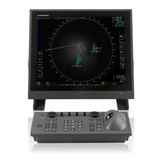
- Page 1 FOIL-200 OPERATORS MANUAL Furuno Finland Oy www.furuno.fi...
-
Page 2: Table Of Contents
TABLE OF CONTENTS FOREWORD................................3 SYSTEM CONFIGURATION..........................4 1. GRAPHICAL USER INTERFACE (GUI)......................5 1.1 Operating mode selections........................6 1.2 Navigational data............................6 1.3 Ice filter parameter adjustments......................7 1.4 Cursor position indicator..........................8 1.5 EBL/VRM................................8 1.6 Display mode selections..........................9 2. INSTALLATION..............................10... -
Page 3: Foreword
FOREWORD A WORD TO THE OWNER OF THE OIL RADAR Congratulations on your choice of the Furuno Finland Oil Radar. Your equipment is designed and constructed to meet the rigorous demands of the marine environment. However, no machine can perform its intended function unless properly operated and maintained. -
Page 4: System Configuration
SYSTEM CONFIGURATION TYPICAL OIL RADAR SYSTEM CONFIGURATION... -
Page 5: Graphical User Interface (Gui)
1. GRAPHICAL USER INTERFACE (GUI) THE OIL RADAR GRAPHICAL USER INTERFACE (GUI) IS BASED ON A SINGLE SCREEN User interface sections 1. Operating mode, Heading mode, vector selection, sweep selection, range/scale and ship center button 2. Cursor position indicator 3. Navigational data 4. -
Page 6: Operating Mode Selections
1.1 OPERATING MODE SELECTIONS Description 1. Motion mode select - Available modes: Head Up TM Head Up RM North Up TM North Up RM 2. Vector – Selection of vector length (Off, 1 min, 3 min, 6 min) 3. Range/Scale indicator – Shows the range used in Radar display. 1.2 NAVIGATIONAL DATA The indicators are passive repeaters of navigational data received from the sensors. -
Page 7: Ice Filter Parameter Adjustments
1.3 OIL FILTER PARAMETER ADJUSTMENTS These parameters affect the behavior of the oil filter Description 1. OIl – toggle ice echoes on/off 2. Echo – toggle navigational radar echoes on/off 3. Brightness – adjust brightness of oil layer. 4. Contrast – adjust contrast of oil layer. 5. -
Page 8: Cursor Position Indicator
1.4 CURSOR POSITION INDICATOR Description 1. Cursor position display (LAT, LON) and range and bearing from own ship position 1.5 EBL/VRM There are two EBL/VRM measurement tools available. You can choose the operating modes of these tools by clicking in the STAB1 or STAB2 box with your mouse. Description 1. -
Page 9: Display Mode Selections
1.6 DISPLAY MODE SELECTIONS Description 1. Click on TMReset to reset vessel position to reset margin. 2. Click on Center ship to place vessel on the center of screen. 3. Use Display to select Day or night palette. -
Page 10: Installation
2. INSTALLATION Sensor and conning positions on ship are in “vessel.config” file, which must be edited at installation time. Description Function 1. Power up oil radar Start up oil radar 2. Open login screen Press Ctrl-Alt F1 to open a login screen 3.