Alvarion BreezeACCESS VL System Manual
Wireless broadband platform
Hide thumbs
Also See for BreezeACCESS VL:
- Release note (8 pages) ,
- Brochure & specs (2 pages) ,
- System manual (273 pages)
Table of Contents
Advertisement
Quick Links
Advertisement
Table of Contents

Related Manuals for Alvarion BreezeACCESS VL


Summary of Contents for Alvarion BreezeACCESS VL
- Page 1 ® BreezeACCESS System Manual SW Version 4.0.27 February 2007 P/N 214484...
-
Page 3: Document History
Per SU Distance Learning Section 4.2.5.6.2, 4.2.6.2.10 ATPC Delta from Minimum SNR Level Section 4.2.6.2.8.3.3 Tx Control Section 4.2.6.2.8.5 BreezeACCESS VL System Manual Document History Description Version/Date Issued Optional support (under SW Version 4.0, license) of FIPS 197 July 2006... - Page 4 SW Version 4.0, July 2006 New feature SW Version 4.0, July 2006 New – display of existing SW Version 4.0, gateways when DRAP is July 2006 enabled. New feature SW Version 4.0, July 2006 BreezeACCESS VL System Manual Version/Date Issued...
- Page 5 Table 4-3 Basic Configuration Menu Section 4.2.4 MIB (Appendix E) Parameters Summary (Appendix F) Using the Feature License Web Application BreezeACCESS VL System Manual Description Version/Date Issued Changed functionality SW Version 4.0, (read only, set to unit’s IP July 2006 Address) Changed default to SW Version 4.0,...
- Page 6 SW Version 4.0.27 October 2006 Updated SW Version 4.0.27 February 2007 Updated functionality SW Version 4.0.27 February 2007 New feature – a procedure SW Version 4.0.27 for password recovery if February 2007 password was lost/forgotten. BreezeACCESS VL System Manual Version/Date Issued...
- Page 7 Sections 4.2.6.3.8, Table 4-3, MIB (Appendix E), Parameters Summary (Appendix F) Noise Immunity Control Sections 4.2.6.2.18, Table 4-3, Parameters Summary (Appendix F) BreezeACCESS VL System Manual Description Version/Date Issued New feature SW Version 4.0.27 February 2007 New feature SW Version 4.0.27...
- Page 8 Statement of Conditions The information contained in this manual is subject to change without notice. Alvarion Ltd. shall not be liable for errors contained herein or for incidental or consequential damages in connection with the furnishing, performance, or use of this manual or equipment supplied with it.
- Page 9 BEYOND THE RANGE OF THE INTENDED USE, OR BY ACCIDENT, FIRE, LIGHTNING OR OTHER HAZARD. Disclaimer (a) The Product is sold on an "AS IS" basis. Alvarion, its affiliates or its licensors MAKE NO WARRANTIES, WHATSOEVER, WHETHER EXPRESS OR IMPLIED, WITH RESPECT TO THE SOFTWARE AND THE ACCOMPANYING DOCUMENTATION.
-
Page 10: Limitation Of Liability
WITH THE SALE, INSTALLATION, MAINTENANCE OR USE OF ITS PRODUCTS. Limitation of Liability (a) ALVARION SHALL NOT BE LIABLE TO THE PURCHASER OR TO ANY THIRD PARTY, FOR ANY LOSS OF PROFITS, LOSS OF USE, INTERRUPTION OF BUSINESS OR FOR ANY INDIRECT, SPECIAL, INCIDENTAL, PUNITIVE OR... -
Page 11: Safety Considerations
The long-term characteristics or the possible physiological effects of Radio Frequency Electromagnetic fields have not been yet fully investigated. BreezeACCESS VL System Manual Legal Rights... - Page 12 (when using external antenna) are grounded and suitable lightning protection devices are used so as to provide protection against voltage surges and static charges. In any event, Alvarion is not liable for any injury, damage or regulation violations associated with or caused by installation, grounding or lightning protection.
-
Page 13: Important Notice
It could also void the user’s authority to operate the equipment. Some of the equipment provided by Alvarion and specified in this manual, is manufactured and warranted by third parties. All such equipment must be... -
Page 15: About This Manual
BreezeACCESS VL system, and for system administrators responsible for managing the system. This manual contains the following chapters and appendices: Chapter 1 – System description: Describes the BreezeAccess VL system and its components. Chapter 2 – Installation: Describes how to install the system components. - Page 16 About This Manual BreezeACCESS VL devices. In addition, a description of all traps relevant to the BreezeACCESS VL devices is provided. Appendix F – Parameters Summary: Provides an at a glance summary of the configuration parameters, value ranges and default values.
-
Page 17: Table Of Contents
1.3 Subscriber Unit ... 7 1.3.1 SU-A/E Subscriber Units ... 7 1.3.2 SU-I Subscriber Units ... 8 1.3.3 The SU-E-BS ... 9 1.4 BreezeACCESS VL B&B (4.9 GHz only)... 10 1.5 Networking Equipment... 11 1.6 Management Systems ... 12 1.6.1 BreezeCONFIG™ ... 12 1.6.2 AlvariSTAR™... - Page 18 2.6.2 BS-PS-AC Power Supply Module ... 60 2.6.3 BS-PS-DC Power Supply Module ... 61 2.6.4 BS-AU Network Interface Module ... 62 2.6.5 Installing the BS-SH Chassis and Modules... 63 Chapter 3 - Commissioning ...65 3.1 Configuring Basic Parameters... 66 xviii BreezeACCESS VL System Manual...
- Page 19 Appendix A - Software Version Loading Using TFTP...195 Appendix B - File Download and Upload Using TFTP ...199 Appendix C - Using the Set Factory Defaults Utility ...203 Appendix D - Preparing the Indoor to Outdoor SU Cable...205 BreezeACCESS VL System Manual Contents...
- Page 20 F.1 Parameters Summary ... 266 F.1.1 Unit Control Parameters ...266 F.1.2 IP Parameters ... 267 F.1.3 Air Interface Parameters ... 267 F.1.4 Network Management Parameters ... 269 F.1.5 Bridge Parameters ...270 F.1.6 Performance Parameters... 271 F.1.7 Service Parameters ... 272 BreezeACCESS VL System Manual...
- Page 21 F.1.8 Security Parameters ... 273 Appendix G - Troubleshooting...275 G.1 Ethernet Port Connection Problems ... 276 G.2 SU Association Problems ... 277 G.3 Low Throughput Problems ... 278 BreezeACCESS VL System Manual Contents...
- Page 23 Figures Figure 2-1: Threaded Holes/Grooves ... 37 Figure 2-2: 3" Pole Installation Using Special Clamps... 37 Figure 2-3: Back View of the new SU-A-ODU ... 38 Figure 2-4: New SU-A-ODU Pole Installation Using the Special Clamp, Vertical Polarization ... 39 Figure 2-5: New SU-A-ODU Pole Installation Using the Special Clamp, Horizontal Polarization ...
- Page 24 Figures Figure 4-1: Main Menu (Administrator Level) ...83 Figure 4-2: Ethernet Connector Pin Assignments ...206 BreezeACCESS VL System Manual xxiv...
- Page 25 Tables Table 1-1: Frequency Bands... 3 Table 1-2: AU Detached Antennas ... 5 Table 1-3: Subscriber Unit ODU Types ... 7 Table 1-4: SU-A/E Subscriber Unit Types ... 8 Table 1-5: SU-I Subscriber Units ... 9 Table 1-6: Radio Specifications ... 14 Table 1-7: Data Communication ...
- Page 26 Table 4-9: VLAN Data Port Functionality for SU - Service Provider Link...157 Table 4-10: VLAN Data Port Functionality for AU - Service Provider Link...158 Table 4-11: Recommended Maximum Modulation Level* ...172 Table 4-12: MIR Ranges and Defaults ...180 Table 4-13: CIR Ranges and Defaults...181 BreezeACCESS VL System Manual xxvi...
-
Page 27: Chapter 1 - System Description
Chapter 1 - System Description In This Chapter: Introducing BreezeACCESS VL, page 2 Base Station Equipment, page 4 Subscriber Unit, page 7 BreezeACCESS VL B&B (4.9 GHz only), page 10 Networking Equipment, page 11 Management Systems, page 12 Specifications, page 14... -
Page 28: Introducing Breezeaccess Vl
These qualities enable service providers to reach a previously inaccessible and broader segment of the subscriber population. BreezeACCESS VL is designed to enable construction of “mixed” cells, where it can be used together with other BreezeACCESS products using GFSK modulation, including BreezeACCESS II, BreezeACCESS MMDS, BreezeACCESS XL and BreezeACCESS V. -
Page 29: Table 1-1: Frequency Bands
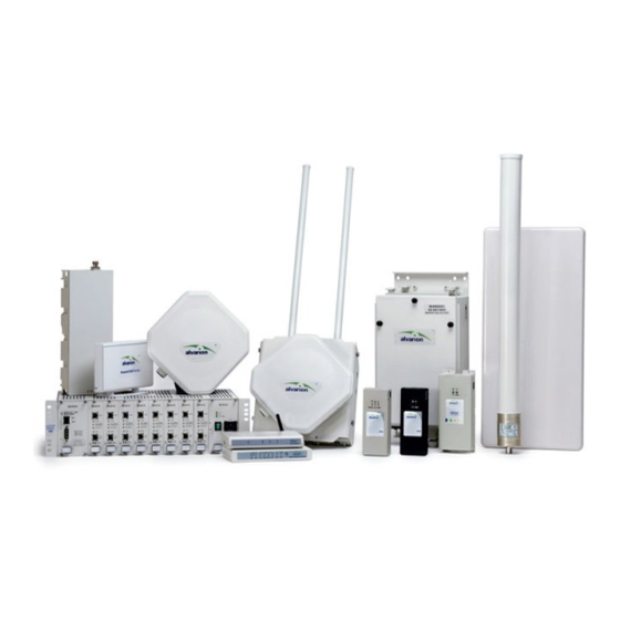
A BreezeACCESS VL system comprises the following: Customer Premise Equipment (CPE): BreezeACCESS VL Subscriber Units (SUs). Base Station Equipment (BS): BreezeACCESS VL Access Units and supporting equipment. Networking Equipment: Standard Switches/Routers supporting connections to the backbone and/or Internet. Management Systems: SNMP-based Management, Billing and Customer Care, and other Operation Support Systems. -
Page 30: Base Station Equipment
BreezeACCESS families using GFSK modulation, then one BS-PS power supply (AC or DC) should be used to provide power to the BreezeACCESS VL Access Units, and a different power supply module, suitable for GFSK equipment, is required for powering the BreezeACCESS GFSK Access Units. -
Page 31: Table 1-2: Au Detached Antennas
The AU-BS Access Unit can serve up to 512 Subscriber Units (124 when Data Encryption is used). The AUS-BS Access Unit can serve up to 8 SU-3 and/or SU-6 and/or SU-I Subscriber Units. NOTE For convenience, all references to AU-BS are applicable also for AUS-BS, unless explicitly stated otherwise. -
Page 32: Standalone "Micro-Cell" Access Unit
(54 VDC) and control from the indoor unit to the outdoor unit. NOTE The AU-D/E-SA-ODU and the AU-D/E-BS-ODU are not interchangeable: The AU-D/E-SA-ODU cannot be used with the BS-AU; the AU-D/E-BS-ODU cannot be used with the standalone IDU. BreezeACCESS VL System Manual... -
Page 33: Subscriber Unit
Subscriber Unit The Subscriber Unit (SU) installed at the customer premises enables the customer data connection to the Access Unit. The Subscriber Unit provides an efficient platform for high speed Internet and Intranet services. The use of packet switching technology provides the user with a connection to the network that is always on, enabling immediate access to services. -
Page 34: Su-I Subscriber Units
A medium rate CPE that supports a single Ethernet device (one MAC address) A medium rate CPE that supports a full LAN An entry level CPE that supports a single Ethernet device (one MAC address) BreezeACCESS VL System Manual New SU-A-ODU... -
Page 35: The Su-E-Bs
SU-I Configuration SU-I-D SU-I-E The SU-I is currently available in the 5.4 GHz and 5.8 GHz bands. NOTE It is recommended to pre-configure the units prior to shipment to end-users. 1.3.3 The SU-E-BS The SU-E-BS is a special variant of a Subscriber Unit, where the indoor unit is designed for installation in the Base Station chassis. -
Page 36: Breezeaccess Vl B&B (4.9 Ghz Only)
Chapter 1 - System Description BreezeACCESS VL B&B (4.9 GHz only) BreezeACCESS VL B&B is available in the 4.9 GHz band to support point-to- point applications. A B&B point-to-point link includes: AU-D-SA-4.9-6-VL: A standalone AU with a 25 dBi, 6° high gain directional antenna. -
Page 37: Networking Equipment
Networking Equipment The Base Station equipment is connected to the backbone through standard data communication and telecommunication equipment. The 10/100BaseT ports of the AU modules can be connected directly to a multi-port router or to an Ethernet switch connected to a router. The point-to-point link from the Base Station to the backbone can be either wired or wireless. -
Page 38: Management Systems
Management Systems The end-to-end IP-based architecture of the system enables full management of all components, from any point in the system. BreezeACCESS VL components can be managed using standard management tools through SNMP agents that implement standard and proprietary MIBs for remote setting of operational modes and parameters. - Page 39 AlvariSTAR provides the following BWA network management functionality: Device Discovery Device Inventory Topology Fault Management Configuration Management Performance Monitoring Device embedded software upgrade Security Management Northbound interface to other Network Management Systems or OSS. Embedded with the entire knowledge base of BWA network operations, AlvariSTAR is a unique state-of-the-art power multiplier in the hands of the service provider that enables the provisioning of satisfied customers.
-
Page 40: Specifications
EN 302 085 V1.2.2 (2003-08) Range 1, RoHS 15 dBi typical net (excluding cable loss) in the 5.150-5.875 GHz band, ~55° horizontal x 10°~12° vertical, vertical polarization, RoHS compliant vertical, vertical polarization, horizontal x BreezeACCESS VL System Manual... - Page 41 Item AU-D Detached Antennas Sensitivity, Minimum (dBm at antenna port, PER<10%, 20 MHz bandwidth Modulation System Description Table 1-6: Radio Specifications Description AU-Ant-5G-16-60: 16 dBi typical, 5.150-5.875 GHz, horizontal x 10 vertical sector antenna, vertical polarization, compliant with EN 302 085 V1.1.2 CS3 AU-Ant-5G-17-90: 17 dBi typical, 5.150-5.875 GHz, horizontal x 6 vertical sector antenna,...
-
Page 42: Data Communication
4.2.6.2.8.1. For information on specific HW and Country Code limitations, see Table 1-7: Data Communication Description IEEE 802.3 CSMA/CD Based on IEEE 802.1Q Based on IEEE 802.1p IP Precedence ToS (RFC791) DSCP (RFC2474) UDP/TCP destination ports BreezeACCESS VL System Manual... -
Page 43: Configuration And Management
FIPS 197 certified encryption (optional for Access Units with HW revision C or higher (excluding AUS units), under license) ESSID SNMP ver 1 client MIB II, Bridge MIB, Private BreezeACCESS VL MIB Configurable or automatic (DHCP client) TFTP TFTP Specifications... -
Page 44: Standards Compliance, General
ETS 300 019 part 2-4 class 4.1E for outdoor Storage ETS 300 019-2-1 class 1.2E Transportation ETS 300 019-2-2 class 2.3 EN 61000-4-5, Class 3 (2kV) FCC Part 15.247 ETSI EN 300 328 ETSI EN 301 893 (2003-04) BreezeACCESS VL System Manual... -
Page 45: Physical And Electrical
1.7.5 Physical and Electrical 1.7.5.1 SU-A/E Subscriber Unit NOTE In the 5.4 and 5.8 GHz band, the equipment may be shipped with a new, smaller size SU-A-ODU that supports both horizontal and vertical polarization. 1.7.5.1.1 Mechanical Table 1-10: Mechanical Specifications, SU-A/E Subscriber Unit Unit General An IDU indoor unit and an ODU outdoor... -
Page 46: Table 1-11: Connectors, Su-A/E Subscriber Unit
3 pin AC power plug 10/100BaseT Ethernet (RJ-45), protected by a waterproof sealing assembly 10/100BaseT Ethernet (RJ-45), protected by a sealing cap 10/100BaseT Ethernet (RJ-45), protected by a waterproof sealing assembly N-Type jack, 50 ohm, lightning protected Details BreezeACCESS VL System Manual... -
Page 47: Table 1-13: Mechanical And Electrical Specifications, Su-I Subscriber Unit
1.7.5.2 SU-I Subscriber Unit 1.7.5.2.1 Mechanical and Electrical Table 1-13: Mechanical and Electrical Specifications, SU-I Subscriber Unit Item Dimensions (cm) Weight (g) Power Consumption DC Power Input (from Power Supply) Mains Power Input (to Power Supply) 1.7.5.2.2 Connectors Table 1-14: Connectors, SU-I Subscriber Unit Connector ETHERNET POWER (48 VDC) -
Page 48: Table 1-15: Mechanical Specifications, Modular Base Station Equipment
43.6 x 25 x 1.0 55 x 25 x 1.1 53 x 26 x 1.1 70cm high, 6cm base diameter 40cm high, 3.2cm base diameter 55 x 25 x 1.7 55 x 7.5 x 5 BreezeACCESS VL System Manual Weight (kg) 4.76 0.15 0.23... -
Page 49: Table 1-16: Connectors, Modular Base Station Equipment
1.7.5.3.2 Connectors Table 1-16: Connectors, Modular Base Station Equipment Unit Connector BS-AU 10/100 BaseT RADIO AU-D-BS-ODU INDOOR BS-PS-AC AC-IN BS-PS-DC -48 VDC Antenna 1.7.5.3.3 Electrical Table 1-17: Electrical Specifications, Modular Base Station Equipment Unit General 240W max. for a fully equipped chassis (1 PS, 6 AU) BS-PS-AC AC power input: 85-265 VAC, 47-65 Hz DC power output: 54 V;... -
Page 50: Table 1-18: Mechanical Specifications, Stand Alone Access Unit
53 x 26 x 1.1 70 cm high, 6 cm base diameter 40 cm high, 3.2 cm base diameter 55 x 25 x 1.7 46 cm high, 5.5 cm base diameter 55 x 7.5 x 5 BreezeACCESS VL System Manual Weight (kg) 0.23... -
Page 51: Table 1-19: Connectors, Stand Alone Access Unit
1.7.5.4.2 Connectors Table 1-19: Connectors, Stand Alone Access Unit Unit Connector ETHERNET RADIO AC IN AU-D-SA-ODU INDOOR Antenna 1.7.5.4.3 Electrical Table 1-20: Electrical Specifications, Stand Alone Access Unit Unit General Power consumption: 25W AC power input: 85-265 VAC, 50-60 Hz AU-D-SA-ODU 54 VDC from the IDU over the indoor-outdoor Ethernet cable System Description... -
Page 52: Table 1-21: 25Dbi Antenna Specifications
2.75”-3.5” pole, 0 to -10° tilt, 2.2kg Description 5.150-5.875 GHz 15dBi net (excluding cable loss). ~55° 10°~12° Linear (Vertical) 33 x 9.3 x 2.1 SMA jack 2 meter, 2 x SMA plug, 3.6 dB max insertion loss BreezeACCESS VL System Manual... -
Page 53: Environmental
1.7.6 Environmental Table 1-23: Environmental Specifications Type Operating temperature Outdoor units Indoor equipment Operating humidity Outdoor units Indoor equipment System Description Unit C to 55 C to 40 5%-95% non condensing, weather protected 5%-95% non condensing Specifications Details... -
Page 55: Chapter 2 - Installation
Chapter 2 - Installation In This Chapter: Installation Requirements, page 30 Equipment Positioning Guidelines, page 34 Installing the Outdoor Unit, page 36 Installing the Universal IDU Indoor Unit, page 46 Installing the SU-I, page 48... -
Page 56: Installation Requirements
Chapter 2 - Installation Installation Requirements This section describes all the supplies required to install the BreezeACCESS VL system components and the items included in each installation package. NOTE Installation requirements for SU-I are provided in section 2.5 on page 48. - Page 57 An IDU to ODU cable kit, including 20m Category 5E Ethernet cable with a shielded RJ-45 connector crimped on one end, a waterproof sealing assembly and two shielded RJ-45 connectors (not applicable for the new SU-A-ODU). 2.1.1.2 Modular Base Station Equipment This section describes the items included in the installation packages for each Modular Base Station system component.
-
Page 58: Additional Installation Requirements
PC. 2.1.1.5 Additional Installation Requirements The following items are also required to install the BreezeACCESS VL system components: Ethernet cable (straight for connecting to a hub/switch etc., crossed for connecting directly to a PC’s NIC) -
Page 59: Indoor-To-Outdoor Cables
Ethernet cable connecting the indoor unit to the user's equipment, together with the length of the Indoor-to-Outdoor cable, should not exceed 100 meters. Use only Category 5E Ethernet cables from approved manufacturers, listed in Table 2-2. Consult with Alvarion specialists on the suitability of other cables. Table 2-2: Approved Category 5E Ethernet Cables Manufacturer Superior Cables Ltd. -
Page 60: Equipment Positioning Guidelines
Failure to do so may void the BreezeACCESS VL product warranty and may expose the end user or Service Provider to legal and financial liabilities. Alvarion and its resellers or distributors are not liable for injury, damage or regulation violations associated with the installation of Outdoor Units or antennas. - Page 61 Equipment Positioning Guidelines The indoor equipment should be installed as close as possible to the location where the indoor-to-outdoor cable enters the building. The location of the indoor equipment should take into account its connection to a power outlet and the customer’s equipment. Installation...
-
Page 62: Installing The Outdoor Unit
(when using external antenna) are grounded and suitable lightning protection devices are used so as to provide protection against voltage surges and static charges. In any event, Alvarion is not liable for any injury, damage or regulation violations associated with or caused by installation, grounding or lightning protection. -
Page 63: Figure 2-1: Threaded Holes/Grooves
Installing the Outdoor Unit Figure 2-1: Threaded Holes/Grooves Figure 2-2 illustrates the method of mounting an outdoor unit on a pole, using the clamps and threaded rods. Figure 2-2: 3" Pole Installation Using Special Clamps NOTE There is a groove on one end of the threaded rod. Be sure to insert the threaded rods with the grooves pointing outward, as these grooves enable you to use a screwdriver to fasten the rods to the unit. -
Page 64: Pole Mounting The New Su-A-Odu
1" to 4". A Tilt Pole Mounting kit, providing a tilt range of +/-15° is available from Alvarion. The Tilt kit can be attached to the ODU and be mounted on a 1" to 4" pole using two 9/16" wide metal bands. -
Page 65: Figure 2-4: New Su-A-Odu Pole Installation Using The Special Clamp, Vertical Polarization
For horizontal polarization install the unit with the Polarization Arrow pointing sideward and the connectors facing downward. 2.3.2.2 Pole Mounting the ODU Using the Clamp Figure 2-4 and Figure 2-5 illustrate how to mount an ODU on a pole, using the clamp and threaded rods. -
Page 66: Figure 2-5: New Su-A-Odu Pole Installation Using The Special Clamp, Horizontal Polarization
Chapter 2 - Installation Figure 2-5: New SU-A-ODU Pole Installation Using the Special Clamp, Horizontal Polarization BreezeACCESS VL System Manual... -
Page 67: Figure 2-6: New Su-A-Odu Pole Installation Using The Tilt Accessory, Vertical Polarization
2.3.2.3 Pole Mounting the ODU with the Tilt Accessory Figure 2-6: New SU-A-ODU Pole Installation Using the Tilt Accessory, Vertical Polarization To mount the ODU on a pole using the Tilt accessory: Attach the Tilt accessory to the ODU using the two pairs of flat washers, spring washers and nuts supplied in the Tilt kit. -
Page 68: Connecting The Grounding And Antenna Cables
The RF connectors should be properly sealed to protect against rain and moisture. Figure 2-7: Bottom Panel of the ODU (all ODUs except to new SU-A-ODU, shown without the sealing assembly) ) is located on the top panel of the AU-ODU/SU-E-ODU. BreezeACCESS VL System Manual... -
Page 69: Connecting The Indoor-To-Outdoor Cable
Figure 2-8: Bottom Panel of the New SU-A-ODU (without IDU COM Sealing Cap) NOTE The MAC Address of the unit is marked on both the ODU and the indoor unit (on the print side of the BS-AU module or on the bottom side of the Universal IDU). If for any reason the ODU is not used with the IDU with which it was shipped, the MAC Address of the system is in accordance with the marking on the ODU. - Page 70 The sealing cap has a special groove allowing to insert an ethernet cable with an already assembled RJ-45 connector through the cap. To expose the groove, lightly squeeze the cap. Carefully insert the cable with the assembled connector through the groove. f or instructions BreezeACCESS VL System Manual...
-
Page 71: Figure 2-10: Inserting The Idu Com Cable Into The Sealing Cap
Figure 2-10: Inserting the IDU COM Cable into the Sealing Cap Connect the Ethernet cable to the IDU COM RJ-45 connector. Put the sealing cap back in its place. Make sure that the small protrusion on the side of the cap fits inside the hole on the connector's protective body. Figure 2-11: Connecting the IDU COM connector and inserting the Sealing Cap Use appropriate sealing material to protect the connection against moisture and humidity. -
Page 72: Installing The Universal Idu Indoor Unit
Connect the 10/100 BaseT ETHERNET connector to the network. The cable connection should be a straight Ethernet if connecting the indoor unit to a hub/switch and a crossed cable if connecting it directly to a PC Network Interface Card (NIC). BreezeACCESS VL System Manual... -
Page 73: Reset Button Functionality
NOTE The length of the Ethernet cable connecting the indoor unit to the user's equipment, together with the length of the Indoor-to-Outdoor cable, should not exceed 100 meters. 2.4.1 RESET Button Functionality Using a sharp object, press the recessed RESET button for a short time to reset the unit and reboot from the Main version. -
Page 74: Installing The Su-I
Portable PC with an Ethernet card and a straight Ethernet cable for configuring parameters using either Telnet or BreezeCONFIG for BreezeACCESS VL application. TFTP server SW is required for downloading SW versions. Other installation tools and materials (means for securing cables to walls, etc.). -
Page 75: Su-I Connectors And Leds
2.5.2 SU-I Connectors and LEDs Name Description Status Self-test and power indication Ethernet Ethernet activity/ connectivity indication W-Link Wireless Link traffic Indication Installation Figure 2-13: SU-I Panel Table 2-3: SU-I Panel Components Green: Power is available and self-test passed. Blinking Amber: Testing (not ready for operation) Red: Self-test failed. -
Page 76: Installation Guidelines
Installation Guidelines The unit can be placed on a desktop or a shelf. It can also be wall mounted using the optional bracket available from Alvarion. It uses a detached antenna. Instructions for the available installation options of the detached antenna... - Page 77 Verify that the green Status LED located on the unit's front panel illuminates, indicating that the power supply to the unit is OK and self test passed successfully. Connect the RF cable supplied with the antenna to the SMA jack located on the unit’s front panel.
-
Page 78: Installing The Detached Antenna
For installation instructions see Section 2.5.5.1 Wall mounting kit with rotation capability, enabling installation on a wall with capability for adjusting the direction. For installation instructions see Section 2.5.5.2. Figure 2-14: SU-I Wall Mount BreezeACCESS VL System Manual... -
Page 79: Wall Mount
Simple window mounting accessories, enabling installation on a glass window (without any capability for adjusting the direction). For installation instructions see Section Window mounting kit with rotation capability, enabling installation on a glass window (with rotation capability for adjusting the direction). For installation instructions see Section NOTE Ensure that the antenna is mounted vertical to the floor, with the connector facing downward, and... -
Page 80: Figure 2-15: Wall Mounting The Antenna
Assemble the bottom L-type plate with the Wall-H L-type plate. Note, the Wall-H plate is the one with the horizontal ellipse on the short side. Make sure the inscriptions are facing upwards. Use two M5 screws to fasten the plates together. Do not over tighten. BreezeACCESS VL System Manual... -
Page 81: Figure 2-16: Wall Mount With Rotation Capability
Attach the assembled plates to the flat rear-side of the antenna. Use the two remaining M5 screws to fasten them. Fasten the antenna to the wall. Use the two #8 screws provided with the kit. Do not over tighten. Connect the antenna cable to the connector located on the bottom side of the antenna. -
Page 82: Figure 2-17: Window Mounting The Antenna
Connect the antenna cable to the connector located on the bottom side of the antenna. Use only the torque key supplied with the antenna. Do not over tighten. Do not use a wrench or a similar tightening tool. Figure 2-17: Window Mounting the Antenna BreezeACCESS VL System Manual... - Page 83 2.5.5.4 Window Mount with Rotation Capability The installation kit includes the following: 4 PHK40*16PT screws (1), 2 M4 washers (2), 2 rotation bars (3) and 2 suction cups (4). Attach the rotation bars to the antenna and the suction cups to the rotation bars.
-
Page 84: Figure 2-18: Window Mounting With Rotation Capability
Chapter 2 - Installation Figure 2-18: Window Mounting with Rotation Capability BreezeACCESS VL System Manual... -
Page 85: Installing The Modular Base Station Equipment
BreezeACCESS families are used, then it is necessary to use two power supply modules: one BS-PS (AC or DC) power supply for the BreezeACCESS VL Access Units and one BS-PS GFSK (AC or DC) for the BreezeACCESS GFSK Access Units. -
Page 86: Bs-Ps-Ac Power Supply Module
Table 2-4: BS-PS LED Functionality Description Green LED. Indicates that the 54V power supply module is OK Green LED. Indicates that the 3.3V power supply module is OK Red LED. Indicates an over temperature condition in the power supply module BreezeACCESS VL System Manual... -
Page 87: Bs-Ps-Dc Power Supply Module
2.6.3 BS-PS-DC Power Supply Module The BS-PS-DC is a DC-to-DC converter that provides power to all the BS-AU modules installed in the BS-SH chassis. Figure 2-21 shows the BS-PS-DC front panel. Figure 2-21: BS-PS-DC Front Panel The BS-PS-DC provides a power input connector, marked -48VDC, for connecting the -48 VDC power source to the module. -
Page 88: Bs-Au Network Interface Module
Do not connect the data equipment to the RADIO port. The RADIO port supplies DC power to the ODU, and this may harm other equipment connected to it. The recessed RESET switch on the front panel is for resetting the outdoor unit. Figure 2-22: BS-AU Front Panel BreezeACCESS VL System Manual... -
Page 89: Installing The Bs-Sh Chassis And Modules
2.6.5 Installing the BS-SH Chassis and Modules This section describes how to install the power supply and Access Unit network interface modules in the Base Station chassis. To install the BS SH chassis and modules: Install the BS-SH chassis in a 19” cabinet. To prevent over-heating, leave a free space of at least 1U between the upper/lower covers of the BS-SH chassis and other units in the cabinet. - Page 90 The length of each of the Ethernet cables (the cable connecting the indoor unit to the user's equipment and the Indoor-to-Outdoor cable) should not exceed 100 meters. Reset the unit using the RESET button after connecting or reconnecting the indoor and outdoor units with the indoor-to-outdoor cable. BreezeACCESS VL System Manual...
-
Page 91: Chapter 3 - Commissioning
Chapter 3 - Commissioning About This Chapter: Configuring Basic Parameters, page 66 Using the Optional Y-cable (New SU-A-ODU), page 69 Aligning the Subscriber Unit Antenna, page 70 Configuring the Subscriber Unit’s Maximum Modulation Level, page 72 Operation Verification, page 74... -
Page 92: Configuring Basic Parameters
Default Value Auto Negotiation 10.0.0.1 255.0.0.0 0.0.0.0 Disable AU: From Ethernet Only SU: From Wireless Only ESSID1 The lowest frequency in the selected Sub-Band All frequencies BreezeACCESS VL System Manual Comment Applicable only if more than one Sub-Band is available... - Page 93 Parameter Transmit Power Maximum Tx Power (SU) Tx Power (AU) Antenna Gain (units with external antenna) ATPC Option Best AU Support (SU) Preferred AU MAC Address (SU) Cell Distance Mode (AU) Maximum Cell Distance (AU) Fairness Factor (AU) Per SU Distance Learning (AU) Maximum Modulation Level (SU) VLAN ID-Management Commissioning...
- Page 94 After the basic parameters are configured, the unit should be reset in order to activate the new configuration. Table 3-1: Basic Parameters Default Value Open System Disable Key 1 Disable Key 1 00……0 (32 zeros, meaning no key) BreezeACCESS VL System Manual Comment Availability of security parameters depends on support according to the country code.
-
Page 95: Using The Optional Y-Cable (New Su-A-Odu)
Using the Optional Y-cable (New SU-A-ODU) A special Y-cable, available from Alvarion, enables to connect a a portable PC directly to the IDU COM port of the SU-A-ODU. This enables the installer to perform the entire process of configuring basic parameters, aligning the antenna and verifying proper operation of the unit right after completing the installation, minimizing the number of times the installer must climb to the roof. -
Page 96: Aligning The Subscriber Unit Antenna
In this case, the antenna is not always directed toward the Base Station. Secure the unit firmly to the pole (SU-A-ODU)/fasten the rotation screws (SU- I antenna). )is On. ) of the ODU is On, indicating that the unit BreezeACCESS VL System Manual... - Page 97 Aligning the Subscriber Unit Antenna NOTE In some cases, the antenna may need to be tilted to ensure that the level at which the SU receives transmissions from the AU (and vice versa) is not too high. As a rule of thumb, if the SU is located at a distance of less than 300 meters from the AU, it is recommended to up-tilt the antenna by approximately 10°...
-
Page 98: Configuring The Subscriber Unit's Maximum Modulation Level
Configure the Maximum Modulation Level according to Table 3-2, using the typical SNR values. It is recommended that a 2 dB margin be added to compensate for possible measurement inaccuracy or variance in the quality of the link. BreezeACCESS VL System Manual... -
Page 99: Table 3-2: Recommended Maximum Modulation Level
Table 3-2: Recommended Maximum Modulation Level* SNR > 23 dB 21 dB < SNR < 23 dB 16 dB < SNR < 21 dB 13 dB < SNR < 16 dB 10 dB < SNR < 13 dB 8 dB < SNR < 10 dB 7 dB <... -
Page 100: Operation Verification
Blinking Amber – Testing (not ready for operation) Red – Self-test failed – fatal error Ethernet activity/ Green –Ethernet link detected. connectivity Amber – No Ethernet connectivity between indication the indoor and outdoor units. BreezeACCESS VL System Manual Functionality... -
Page 101: Table 3-4: Su-Odu Leds
Name W-LINK Status SNR BAR (SU-RA) Commissioning Table 3-4: SU-ODU LEDs Description Wireless Link Green – Unit is associated with an AU, no wireless link activity Indictor Blinking Green – Data received or transmitted on the wireless link. Blinking rate is proportional to wireless traffic rate Off –... -
Page 102: Table 3-5: Su-Odu Snr Bar Led Functionality
SNR > 8 dB SNR > 13 dB SNR > 19 dB SNR > 26 dB SNR > 31 dB SNR > 38 dB SNR > 44 dB Signal is too high (SNR > 50 dB) BreezeACCESS VL System Manual SNR (typical) -
Page 103: Indoor Unit Verification
3.5.2 Indoor Unit Verification To verify the correct operation of the indoor equipment, examine the LED indicators located on the top panel of the SU IDU and AU IDU units, or on the front panel of the BS-AU module. Table 3-6 provides information for the BS-AU IDU LEDs. Table 3-7 lists the LEDs of the PS1073 IDU. -
Page 104: Su-I Unit Verification
Off – No Ethernet connectivity has been detected between the outdoor end Ethernet unit and the device connected to the connectivity indoor unit. Green – Self-test passed and Ethernet connection confirmed by the outdoor unit (Ethernet integrity check passed). BreezeACCESS VL System Manual Functionality... -
Page 105: Table 3-8: Su-I Leds
Name Status Ethernet W-Link Commissioning Table 3-8: SU-I LEDs Description Self-test and power Green: Power is available and self-test indication passed. Blinking Amber: Testing (not ready for operation) Red: Self-test failed. Fatal error Ethernet activity/ Green: Ethernet link between the SU-I and connectivity indication the data equipment is detected, no activity Blinking Green: Ethernet connectivity is... -
Page 106: Verifying The Ethernet Connection (Modular Base Station)
SNR > 8 dB SNR > 13 dB SNR > 19 dB SNR > 26 dB SNR > 31 dB SNR > 38 dB SNR > 44 dB Signal is too high (SNR > 50 dB) BreezeACCESS VL System Manual SNR (typical) -
Page 107: Chapter 4 - Operation And Administration
Chapter 4 - Operation and Administration In This Chapter: Working with the Monitor Program, page 82 Menus and Parameters, page 85... -
Page 108: Working With The Monitor Program
If you forgot the password, type "h" at the Access Level selection prompt. Type “Recover” at the prompt to get a challenge string consisting of 8 characters. Contact Alvarion's Customer Service and give them the challenge string (after user identification) to receive a one-time password. -
Page 109: Common Operations
BreezeACCESS VL/AU Official Release Version – 4.0.27 Release Date: Feb 13 2007, 12:59:23 Main Menu ========== 1 – Info Screens 2 – Unit Control 3 - Basic Configuration 4 – Site Survey 5 - Advanced Configuration x - Exit >>>... - Page 110 Refer to Appendix F for information on which parameters are run time configurable, which means that the unit need not be reset for the parameter to take effect, and which parameters do require that the unit be reset. BreezeACCESS VL System Manual...
-
Page 111: Menus And Parameters
Menus and Parameters The following sections describe the menus and parameters provided by the Monitor program. 4.2.1 Main Menu The Main Menu enables to access the following menus, depending on your access level, as described in section Info Screens: Provides a read only display of current parameter values. Available at all access levels. - Page 112 SCANNING: The SU is searching for an AU with which to associate. If the DFS Option is enabled and the SU is currently looking for its previous AU, the AU’s MAC Address will be displayed. ASSOCIATED: The SU is associated with an AU. BreezeACCESS VL System Manual...
- Page 113 AU MAC Address (SU only): The MAC address of the AU with which the unit is currently associated. If the unit is not associated with any AU, the address defaults to the IEEE broadcast address, which is FF-FF-FF-FF-FF-FF. Unit Hardware Version: The version of the outdoor unit hardware. Unit BOOT Version: The version of the BOOT SW.
- Page 114 FTP Log File Destination Directory Event Log Policy 4.2.2.2 Show Basic Configuration The Show Basic Configuration menu is a read only menu that displays the current values of the parameters included in the Basic Configuration menu. BreezeACCESS VL System Manual...
- Page 115 4.2.2.3 Show Advanced Configuration The Show Advanced Configuration menu enables to access the read only sub menus that display the current values of the parameters included in the applicable sub menus of the Advanced Configuration menu. 4.2.2.4 Show Country Dependent Parameters Each country has its radio regulation regarding transmissions in the applicable bands that affect parameters such as available frequencies, bandwidth, transmit power, etc.
-
Page 116: Unit Control Menu
The Unit Control menu enables configuring control parameters for the unit. The Unit Control menu includes the following options: Reset Unit Default Settings Change Unit Name Change Password Flash Memory Control SW Version Download Configuration File Upload/Download Log Out Timer Appendix BreezeACCESS VL System Manual... -
Page 117: Default Settings
Ethernet Port Negotiation Mode Change System Location Event Log Menu Feature Upgrade 4.2.3.1 Reset Unit The Reset Unit option enables resetting the unit. After reset, any modifications made to the system parameters are applied. 4.2.3.2 Default Settings The Set defaults submenu enables resetting the system parameters to a predefined set of defaults or saving the current configuration as the set of Operator Defaults. -
Page 118: Table 4-2: Parameters Not Reset After Set Complete Factory/Operator Defaults
FTP Gateway IP address* (see note below) FTP User Name* (see note below) FTP Password* (see note below) Ethernet Port Negotiation Mode Selected Sub-Band (AU) Frequency (AU) DFS Option (AU) Frequency Subset (AU) Antenna Gain (AU) BreezeACCESS VL System Manual... -
Page 119: Table 4-3: Parameters That Are Not Reset After Set Partial Factory/Operator Defaults
Table 4-3: Parameters that are not reset after Set Partial Factory/Operator Defaults Parameters Group Unit Control parameters IP Parameters Security Parameters Operation and Administration Menus and Parameters Parameter Passwords Ethernet Port Negotiation Mode FTP Server IP address FTP Gateway IP Address FTP User Name FTP Password IP Address... - Page 120 Frequency Subset (AU) ATPC Option (AU) Transmit Power Maximum Tx Power (SU) Tx Control (AU) Best AU Support (SU) Preferred AU MAC Address (SU) All Noise Immunity Control parameters AP Client IP Address (SU) Adaptive Modulation Decision Thresholds BreezeACCESS VL System Manual...
- Page 121 Table 4-3: Parameters that are not reset after Set Partial Factory/Operator Defaults Parameters Group Bridge Parameters Service Parameters 4.2.3.2.1.3 Set Complete Operators Defaults Select this option to reset the unit to the Operator Defaults configuration, excluding several parameters that are listed in Table 4-2. 4.2.3.2.1.4 Set Partial Operator Defaults Select this option to reset the unit to the Operator Defaults configuration, excluding the parameters that are required to maintain connectivity and...
-
Page 122: Change Password
New parameters are loaded with their default values. Select from the following options: for a list of the default passwords for each of the access levels. BreezeACCESS VL System Manual... - Page 123 Reset and Boot from Shadow Version: Activates the shadow (backup) software version. The unit is reset automatically. Following the next reset the unit will switch to the main version. Use Running Version After Reset: Defines the current running version as the new main version.
- Page 124 Execute FTP Get Operator Defaults File (cmr) Execute FTP Put Operator Defaults File (cmr) FTP Configuration File Source Dir: The FTP Configuration File Source Dir option enables defining the source directory of the configuration/Operator Defaults file. BreezeACCESS VL System Manual...
- Page 125 Valid values: A string of up to 80 printable ASCII characters. To clear the field press "." The default is an empty string. Configuration File FTP File Name: The Configuration File FTP File Name option enables defining the name of the configuration file to be uploaded/downloaded.
- Page 126 MIB2. The System Location is also displayed as a part of the Monitor menu’s header. Valid values: A string of up to 35 printable ASCII characters. The default system location is an empty string. BreezeACCESS VL System Manual...
- Page 127 4.2.3.11 Event Log Menu The Event Log Menu enables controlling the event log feature. The event log is an important debugging tool and a flash memory sector is dedicated for storing it. Events are classified according to their severity level: Message (lowest severity), Warning, Error or Fatal (highest severity).
- Page 128 FTP Password: The FTP Password option enables defining the password to be used for accessing the FTP server that is hosting the file. Valid values: A string of up to 18 printable ASCII characters. The default is: vx BreezeACCESS VL System Manual...
-
Page 129: Basic Configuration Menu
Show FTP Event Log File Upload Parameters: Displays the current values of the Event Log Upload parameters. NOTE There is one set of general FTP parameters (FTP Server IP Address, FTP Gateway IP Address, FTP User Name and FTP Password). This set (or relevant parts of the set) serves the SW Download procedure, the Configuration File Upload/Download procedure and the Event Log File Upload procedure. - Page 130 Best AU Parameters (SU) Best AU Support Preferred AU MAC Address Cell Distance Parameters (AU) Cell Distance Mode Maximum Cell Distance Fairness Factor Per SU Distance Learning ATPC Parameters ATPC Option Transmit Power for a description of these parameters. BreezeACCESS VL System Manual...
-
Page 131: Site Survey Menu
Maximum Tx Power (SU) Tx Control (AU) Antenna Gain Refer to section 4.2.6.2 4.2.4.1.3 Performance Parameters Maximum Modulation Level (SU) Refer to section 4.2.6.5 4.2.4.1.4 Bridge Parameters VLAN Support VLAN ID – Management Refer to section 4.2.6.4 4.2.4.1.5 Security Parameters Authentication Algorithm Data Encryption Option Security Mode... -
Page 132: Traffic Statistics
VLAN(s). For units with HW revision C and higher, the maximum length of an Ethernet packet that can be accepted from or transmitted to the Ethernet port (excluding CRC) is 1600 bytes, including VLAN(s) for single or double-tagged packets. BreezeACCESS VL System Manual... - Page 133 High queue. Any frame coming from the Ethernet port, which is meant to reach another BreezeACCESS VL unit via the wireless port (as opposed to messages intended for stations behind other BreezeACCESS VL units), is sent to the High queue, regardless of the priority configuration.
- Page 134 Total Tx events: The total number of transmit events. Typically, transmission events include cases where transmission of a frame was delayed or was aborted before completion. The following additional counters are displayed to indicate the reason for and the nature of the event: 4.2.6.5.10 BreezeACCESS VL System Manual...
- Page 135 Dropped: The number of dropped frames, which are unsuccessfully retransmitted without being acknowledged until the maximum permitted number of retransmissions. Underrun: The number of times that transmission of a frame was aborted because the rate of submitting frames for transmission exceeds the available transmission capability.
-
Page 136: Ping Test
Show Ping Test Values: Displays the current values of the ping test parameters, the transmission status, which means whether it is currently sending or not sending pings, the number of pings sent, and the number of pings received, which means the number of acknowledged frames. BreezeACCESS VL System Manual... - Page 137 4.2.5.3 Link Quality (SU only) The Link Quality submenu enables viewing continuously updated information on the quality of the wireless link. The Link quality submenu includes the following options: 4.2.5.3.1 Continuous Average SNR Display The Continuous Average SNR Display option displays continuously updated information regarding the average quality of the received signal, using Signal to Noise Ratio (SNR) measurements.
- Page 138 Ethernet and wireless ports. The MAC address of the internal Operating System stack, which also appears twice. Alvarion's Multicast address (01-20-D6-00-00-01, which also appears twice. The system treats this address as a Broadcast address. The Ethernet Broadcast address (FF-FF-FF-FF-FF-FF).
- Page 139 NOTE There is no aging algorithm for associated SUs. An SU is only removed from the list of associated SUs under the following conditions: A SNAP frame is received from another AU indicating that the SU is now associated with the other AU.
-
Page 140: Table 4-4: Authentication And Association Process
The current number of entries. This is the number of currently associated SUs. Direction Status in AU AU → SU SU → AU Not authenticated AU → SU Authenticated SU → AU Authenticated AU → SU Associated SU → AU Associated SU ↔ AU Associated BreezeACCESS VL System Manual... - Page 141 NOTE There is no aging algorithm for associated SUs. An SU is only removed from the list of associated SUs under the following conditions: A SNAP frame is received from another AU indicating that the SU is now associated with the other AU.
- Page 142 Ethernet and wireless ports. The MAC address if the internal Operating System’s stack, which also appears twice. Alvarion's Multicast address (01-20-D6-00-00-01), which also appears twice. The system treats this address as a Broadcast address. Alvarion's special Multicast address (01-20-D6-00-00-05), reserved for future use.
- Page 143 Reset Counters: Select this option to reset the Per Modulation Level Counters. The statistics show the number of frames accumulated in different categories since the last reset. For SUs, the Per Modulation Level Counters display the following information for each modulation level supported by the unit: SUCCESS: The total number of successfully transmitted unicasts at the applicable modulation level.
- Page 144 Select this option to view information on current security related parameters of relevant units. For each relevant unit, identified by its MAC address, the following details are displayed: Security Mode: WEP, AES OCB or FIPS 197. BreezeACCESS VL System Manual...
- Page 145 Authentication Algorithm: Shared Key or Open System. Data Encryption Option: Enable or Disable. 4.2.5.6.4 Show Link Capability by AU (SU only) Select this option to view all capabilities information (General, wireless Link Configuration, Security Configuration) of a selected AU (by its MAC address). 4.2.5.6.5 Show Link Capability by SU (AU only) Select this option to view all capabilities information (General, Wireless Link Configuration, Security Configuration) of a selected SU (by its MAC address).
-
Page 146: Advanced Configuration Menu
The IP Address parameter defines the IP address of the unit. The default IP address is 10.0.0.1. 4.2.6.1.2 Subnet Mask The Subnet Mask parameter defines the subnet mask for the IP address of the unit. The default mask is 255.0.0.0. BreezeACCESS VL System Manual... -
Page 147: Dhcp Client
4.2.6.1.3 Default Gateway Address The Default Gateway Address parameter defines the IP address of the unit's default gateway. The default value for the default gateway address is 0.0.0.0. 4.2.6.1.4 DHCP Client The DHCP Client submenu includes parameters that define the method of IP parameters acquisition. - Page 148 "global" ESSID, namely "Operator ESSID", can be configured in the AU. If the Operator ESSID Option is enabled at the AU, the Beacon frames transmitted by it will include both the ESSID and Operator ESSID. The SU shall BreezeACCESS VL System Manual...
- Page 149 regard such frames if either the ESSID or the Operator ESSID matches it own ESSID. The ESSID of the AU with which the SU is eventually associated is defined as the Run-Time ESSID of the SU. Typically, the initial ESSID of the SU is configured to the value of the Operator ESSID.
- Page 150 5800 MHz, frequencies 5790 MHz and 5810 MHz should not be used as well. These frequencies are marked in the database as Adjacent to Radar, and will be treated the same as Radar Detected frequencies. BreezeACCESS VL System Manual...
- Page 151 Before ceasing transmission on the frequency where radar signals had been detected, the AU sends a special disassociation message to its associated SUs. This message includes an indication whether the SUs should wait for this AU. If the SUs should wait, the message includes also the waiting time. During this time each SU searches for the AU in the defined frequencies subset.
- Page 152 During this time the AU does not transmit. The range is 1 to 3600 seconds. The default is 60 seconds. BreezeACCESS VL System Manual...
- Page 153 4.2.6.2.4.3.4 Channel Avoidance Period The Channel Avoidance Period defines the time that the frequency will remain marked in the database as Radar Detected or Adjacent to Radar after detecting radar activity. These frequencies will not be used when searching for a new frequency.
- Page 154 Maximum TX Power will be set to the maximum defined by the country code. TX Power will be set to the maximum defined by the country code. BreezeACCESS VL System Manual...
- Page 155 The Modulation Level will be set to the maximum modulation level defined by the country code. The Multicast Modulation Level will be set to the minimum modulation level defined by the country code. The Burst Mode will be set to enable if the country code supports burst mode, and the burst duration will be set to default.
- Page 156 The Best AU Support option enables or disables the Best AU selection feature. The default is Disable. NOTE If the Best AU feature is not used, the SU associates with the first AU it finds whose ESSID or Operator ESSID is identical to its own ESSID. BreezeACCESS VL System Manual...
- Page 157 4.2.6.2.6.2 Number Of Scanning Attempts When the Best AU option is enabled, the SU gathers information on neighboring AUs for approximately 2 seconds on each of the scanned frequencies. The Number of Scanning Attempts parameter defines the number of times that the process will be repeated for all relevant frequencies.
- Page 158 The weight of history (the previous value) in the formula used for calculating the average SNR is determined BreezeACCESS VL System Manual...
- Page 159 by a configurable parameter. In addition, the higher the time that has passed since the last calculation, the lower the impact of history on the calculated average. If the average SNR is not in the configured target range, the AU transmits to the SU a power-up or a power-down message.
- Page 160 The minimum value for the Maximum Tx Power is -10 dBm. The maximum value depends on several unit properties and parameters: The HW revision of the unit The Maximum Allowed Tx Power as defined for the applicable Sub-Band. 4.2.2.4 BreezeACCESS VL System Manual...
- Page 161 The Maximum EIRP as defined for the applicable Sub-Band, together with the value of the Antenna Gain. In certain countries the Maximum EIRP of some equipment types cannot exceed a certain value. In these cases the Transmit Power cannot exceed the value of (Maximum EIRP – Antenna Gain). For information on how to view the Sub-Bands supported by the unit and the supported parameters’...
- Page 162 4.2.6.2.8.5 Tx Control (AU only) The Tx Control option enables turning Off/On the AU’s transmitter, or having the AU Tx status controlled by the status of the Ethernet port/link. If the selected option is Ethernet Status Control, then: BreezeACCESS VL System Manual...
-
Page 163: Antenna Gain
If the Ethernet link is down, the AU transmitter will be switched to Off If the Ethernet link is up, the AU transmitter will be switched to On. This feature can be used during maintenance or testing to avoid transmissions using undesired parameters. - Page 164 SUs it serves will be determined manually (using the Maximum Cell Distance parameter) or automatically. In addition, the Per SU Distance Learning feature is supported only when the Cell Distance Mode is set to Automatic. The Options are Automatic or Manual. BreezeACCESS VL System Manual...
- Page 165 The default is Automatic. 4.2.6.2.10.2 Maximum Cell Distance The Maximum Cell Distance parameter allows configuring the maximum distance when the Cell Distance Mode option is Manual. The range is 0 to 54 (Km). The value of 0 has a special meaning for No Compensation: Acknowledge Time Out is set to a value representing the maximum distance of 54 km.
- Page 166 Minimum Contention Window parameter in both units must be configured to 0 to disable the contention window back-off algorithm. ) after reaching a decision that the medium has become free. (section 4.2.6.5.2 BreezeACCESS VL System Manual ) parameter in both units is...
- Page 167 4.2.6.2.12 Maximum Number of Associations (AU only) The Maximum Number of Associations parameter defines the maximum number of Subscriber Units that can be associated with the selected AU, while still guaranteeing the required quality of service to customers. Available values for AU-BS and AU-SA range from 0 to 512. For AUS-BS and AUS-SA the range is from 0 to 8.
- Page 168 At the end of the period the unit will reset automatically regaining normal operability upon start up. The Spectrum Analysis submenu includes the following options: BreezeACCESS VL System Manual...
- Page 169 4.2.6.2.15.1 Spectrum Analysis Channel Scan Period The Spectrum Analysis Channel Scan Period is the period of staying on each channel during each cycle for information gathering when performing spectrum analysis. Range: 2-30 seconds. Default value: 5 seconds. 4.2.6.2.15.2 Spectrum Analysis Scan Cycles The Spectrum Analysis Scan Cycle is the number of scanning cycles when performing Spectrum Analysis.
- Page 170 AU processing power of the unit, delivering higher packet processing efficiency. This ANI mechanism is triggered by the rate of detected Physical Errors and it is modifying different thresholds affecting the immunity to specific interference types. BreezeACCESS VL System Manual...
- Page 171 ANI mechanism may not function properly. It is strongly recommended to consult with Alvarion experts before switching to manual mode and modifying any of the parameters. The general rules for using the Noise Immunity Control parameters are: In the SU, if performance (Modulation Level) is lower than expected based on the SNR, try switching to Manual mode without changing any of the parameters.
- Page 172 Sensitivity is automatically forced to high for the duration of the test. The default is High. 4.2.6.2.18.6 Show Noise Immunity Select this option to view the current values of the Noise Immunity Control parameters, and some additional parameters of the ANI mechanism. BreezeACCESS VL System Manual...
- Page 173 4.2.6.3 Network Management Parameters The Network Management Parameters menu enables protecting the Unit from unauthorized access by defining a set of discrete IP addresses as well as IP address ranges from which the unit can be managed using protocols such as Telnet, FTP, TFTP, SNMP, DHCP and ICMP.
- Page 174 Access to Network Management parameter only by stations with IP addresses matching one of the entries in the Set Network Management IP Addresses parameter. The default selection is Disable. BreezeACCESS VL System Manual...
- Page 175 4.2.6.3.3 Set Network Management IP Address The Set Network Management IP Address option enables defining up to 10 IP addresses of devices that can manage the unit if the Network Management Filtering option is enabled. The default Network Management IP Address is 0.0.0.0 (all 10 addresses). 4.2.6.3.4 Delete a Network Management IP Address The Delete Network Management IP Address option enables deleting IP address entries from the Network Management IP Addresses list.
-
Page 176: Snmp Traps
SU the IP address of the WiFi AP connected to it, providing availability of the IP address information for remote management of the AP. The default AP Client IP Address is 0.0.0.0 (meaning none). system comprises a self-contained combination of an BreezeACCESS VL System Manual... -
Page 177: Vlan Support
VLAN is included in the VLAN Tag Header, which is inserted in each frame between the MAC header and the data. VLAN implementation in BreezeACCESS VL units supports frame routing by port information, whereby each port is connected to only one VLAN. - Page 178 4.2.6.4.1.2 VLAN ID-Management The VLAN ID-Management is applicable for all link types. It enables defining the VLAN ID for management frames, which identifies remote stations for management purposes. This applies to all management applications using BreezeACCESS VL System Manual...
- Page 179 protocols such as SNMP, TFTP, ICMP (ping), DHCP and Telnet. All servers/stations using these protocols must tag the management frames sent to the unit with the value of the VLAN ID-Management parameter. Valid values: 1 to 4094 or 65535 (No VLAN). The default value is 65535.
-
Page 180: Table 4-5: Vlan Management Port Functionality
Table 4-5: VLAN Management Port Functionality Action Tagged frames, matching VID-M Untagged frames when VID-M=65535 Tagged frames, matching VID-M Tagged frames, matching VID-M Untagged frames when VID-M=65535 Tagged frames, matching VID-M Insert VID-M, PID-M BreezeACCESS VL System Manual Management Port - Internal... -
Page 181: Table 4-6: Vlan Data Port Functionality - Access Link
Table 4-6: VLAN Data Port Functionality - Access Link Receive from Ethernet Accept from Wireless Tag Insert Tag Remove Table Legend: VID-D: VLAN ID-Data PID-D: VLAN Priority-Data 4.2.6.4.1.3.2 Trunk Link Trunk Link transfers only tagged frames, as all devices connected to the unit are VLAN aware. -
Page 182: Table 4-7: Vlan Data Port Functionality - Trunk Link
If Forwarding is enabled, only frames with VLAN ID values which are included in the Forwarding list Tagged frames If Forwarding is enabled, only frames with VLAN ID values which are included in the Forwarding list Action BreezeACCESS VL System Manual Data Port – AU and SU... -
Page 183: Table 4-9: Vlan Data Port Functionality For Su - Service Provider Link
4.2.6.4.1.3.4 Service Provider Link A Service Provider Link transfers both single tagged frames (Service Provider tag) and double-tagged frames (Service Provider tag + Customer tag). The Service Provider tag includes the Service Provider VLAN ID and the VLAN QinQ Ethertype. The following tables summarize the functionality of the SU/AU data port for a Service Provider Link. -
Page 184: Table 4-10: Vlan Data Port Functionality For Au - Service Provider Link
If Forwarding is enabled, only frames with VLAN ID values which are included in the Forwarding List Double tagged frames: If Forwarding is disabled If Forwarding is enabled, only frames with Service Provider VLAN ID values which are included in the Forwarding List BreezeACCESS VL System Manual... - Page 185 4.2.6.4.1.4.1 VLAN Forwarding Support The VLAN Forwarding Support option enables or disables the VLAN Forwarding feature. Available selections are Disable and Enable. The default selection is Disable. 4.2.6.4.1.4.2 Add Forwarding VLAN ID The Add Forwarding VLAN ID option enables adding a VLAN ID to the VLAN Forwarding List.
- Page 186 Both single-tagged frames (having Service Provider VLAN ID tag) and double- tagged frames (having Service Provider VLAN ID and customer VLAN ID tags) with matching VLAN ID are forwarded to the Ethernet Port (provided the Ethertype of the tag matches the configured VLAN QinQ Ethertype). BreezeACCESS VL System Manual...
- Page 187 Before transmitting the frames to the Ethernet port, the Service Provider VLAN ID tag is removed. The Service Provider VLAN ID affects frames received from the Ethernet link port, as follows: A Service Provider tag, that includes the configured Service Provider VLAN ID (and the VLAN QinQ Ethertype) is inserted in all frames, both tagged and untagged, before transmission to the wireless link.
- Page 188 On Wireless Port Only - filters broadcast messages received from the wireless link port. On Both Ethernet and Wireless Ports - filters broadcast messages received from both the Ethernet and wireless link ports. The default selection is Disable. BreezeACCESS VL System Manual...
- Page 189 4.2.6.4.2.2 DHCP Broadcast Override Filter The DHCP Broadcast Override Filter option enables or disables the broadcasting of DHCP messages. Even if according to the selected option in the Filter Options parameter, broadcast messages should be filtered, DHCP broadcasts are transmitted if this parameter is set to Enable. Select from the following options: Disable - DHCP Broadcast messages are filtered or transmitted according to the general filtering criteria in the Filter Options parameter.
- Page 190 (or since the time that the limit has been exceeded). BreezeACCESS VL System Manual...
- Page 191 The Bridge Aging Time parameter enables selecting the bridge aging time for learned addresses of devices on both the wired and wireless sides, not including BreezeACCESS VL units. The available range is 20 to 2000 seconds. The default value is 300 seconds.
- Page 192 The AU that receives this SNAP message learns from it the new location of the clients. It forwards the SNAP to other AUs and Layer-2 networking equipment via its Ethernet port, to facilitate uninterrupted connectivity and BreezeACCESS VL System Manual...
- Page 193 correct routing of transmissions to these clients. The new AU as well as the previous AU with which the SU was associated, will forward the SNAP messages to all other SUs associated with them. The default is Disable. 4.2.6.4.9 Ports Control (SU only) The Ports Control sub-menu includes the Ethernet Port Control option: 4.2.6.4.9.1 Ethernet Port Control The Ethernet Port Control option allows enabling or disabling non-management...
-
Page 194: Rts Threshold
The default value is 60 bytes for SUs. For AUs with HW revision C the default is 4032, and for AUs with HW revision A or B the default is 2200. It is recommended that these values be used to ensure that RTS/CTS is never used in the AU. BreezeACCESS VL System Manual... - Page 195 The Minimum Contention Window parameter determines the time that a unit waits from the time it has concluded that there are no detectable transmissions by other units until it attempts to transmit. The BreezeACCESS VL system uses a special mechanism based on detecting the presence of a carrier signal and analyzing the information contained in the transmissions of the AU to estimate the activity of other SUs served by the AU.
- Page 196 Survey menu. If the measured SNR is less than a certain threshold, it is recommended that the maximum modulation level of the SU be decreased in accordance with Table 4-11, using the values of typical sensitivity. It is 4.2.2.4 ) is enabled, it 4.2.6.5.9 BreezeACCESS VL System Manual...
- Page 197 Menus and Parameters recommended to add a 2 dB safety margin to compensate for possible measurement inaccuracy or variance in the link quality. NOTE The SNR measurement at the AU is accurate only when receiving transmissions from the applicable SU. If necessary, use the Ping Test utility in the Site Survey menu to verify data transmission.
-
Page 198: Table 4-11: Recommended Maximum Modulation Level
Available values: -1 to 32. -1 is for no weight for history, meaning that average SNR equals the last measured SNR. Default value: 5 Maximum Modulation Level BreezeACCESS VL System Manual... - Page 199 4.2.6.5.7 Number of HW Retries The Number of HW Retries parameter defines the maximum number of times that an unacknowledged packet is retransmitted. When the Adaptive Modulation Algorithm is disabled, a frame will be dropped when the number of unsuccessful retransmissions reaches this value.
- Page 200 Maximum Modulation Level parameter. If the Maximum Modulation Level is set at the lowest possible level, the Adaptive Modulation algorithm has no effect. BreezeACCESS VL System Manual...
- Page 201 The default selection is Enable. 4.2.6.5.9.2 Minimum Interval Between Adaptive Modulation Messages The Minimum Interval Between Adaptive Modulation Messages sets the minimum interval between two consecutive adaptive modulation messages, carrying information on the SNR of received signals. The messages in the AU include SNR information on all the SUs associated with it.
- Page 202 (Concatenated Frame Double) or more data frames (Concatenated Frame More). The Concatenation Parameters submenu includes: 4.2.6.5.10.1 Concatenation Option The Concatenation Option enables or disables the concatenation mechanism. The default is Enable. BreezeACCESS VL System Manual...
- Page 203 4.2.6.5.10.2 Maximum Concatenated Frame Size The Maximum Concatenated Frame Size parameter defines the maximum size (in bytes) for a concatenated frame. The range is: 1256 to 2200 bytes for units with HW revision A or B 256 to 4032 bytes for units with HW revision C or higher The Default values are: 2200 for units with HW revision A or B 4032 for units with HW revision C or higher...
- Page 204 DHCP server. The DHCP Unicast Override Filter option enables to overcome this problem. When enabled, unicast DHCP messages pass, overriding the user filtering mechanism. The default is Disable DHCP Unicast. BreezeACCESS VL System Manual...
- Page 205 4.2.6.6.1.6 Show User Filtering Parameters The Show All User Filtering Parameters option displays the current value of the User Filtering Option and the list of User Filtering addresses, subnet masks and ranges. 4.2.6.6.2 MIR and CIR Parameters The CIR (Committed Information Rate) specifies the minimum data rate guaranteed to the relevant subscriber.
-
Page 206: Table 4-12: Mir Ranges And Defaults
Range (Kbps) Type SU-3 128-2,048 SU-6 128-4,096 SU-54 128-53,888 SU-I 128-2,048 Table 4-12: MIR Ranges and Defaults Default (Kbps) Range (Kbps) 2,048 128-3,072 4,096 128-6,016 32,896 128-53,888 2,048 128-6,016 BreezeACCESS VL System Manual MIR Downlink Default (Kbps) 3,072 6,016 32,896 6,016... -
Page 207: Table 4-13: Cir Ranges And Defaults
CIR Uplink Unit Range (Kbps) Type SU-3 0-2,048 SU-6 0-4,096 SU-54 0-45,056 SU-I 0-2,048 4.2.6.6.2.5 Maximum Burst Duration (SU and AU) Sets the maximum time for accumulating burst transmission rights according to the Burst Duration algorithm. Available values range from 0 to 2000 (milliseconds). The default value is 5 (milliseconds), enabling a maximum burst of (0.005 X CIR) Kbps after a period of inactivity of 5 milliseconds or more. - Page 208 The Low Priority Traffic Minimum Percent parameter can be used to prevent starvation of low priority traffic by ensuring that a certain number of low priority packets is transmitted even at the expense of high priority traffic. BreezeACCESS VL System Manual...
- Page 209 In addition, the Wireless Link Prioritization, which is a licensable feature, enables to configure parameters that affect the prioritization of traffic in the wireless link for packets with high/low priority from different units. 4.2.6.6.3.1 VLAN Priority Threshold The VLAN Priority Threshold is applicable for Trunk and Hybrid Links only. It enables defining the value of the VLAN Priority Threshold.
- Page 210 The UDP Port Ranges menu includes the following options: UDP RTP/RTCP Prioritization: Voice over IP is transported using Real Time Protocol (RTP). The Real Time Control Protocol (RTCP) is used to control the RTP. When an application uses RTP/RTCP, it chooses for destination ports BreezeACCESS VL System Manual...
- Page 211 consecutive numbers: RTP port is always an even number, and the port with the odd number following it will be assigned to RTCP. If the administrator selects to prioritize only the RTP packets, then all the packets with an odd numbered destination port will always have Low priority. The packets with an even number for destination port will receive High priority, if the port number is included in the specified ranges.
- Page 212 In ranges, a hyphen is used to separate between start and end port numbers. A comma is used to separate between entries. For example: 8900,9000-9005,9010,9016-9017. Delete All TCP Port Ranges: This option enables deleting all TCP port ranges from the list of priority port numbers. BreezeACCESS VL System Manual...
- Page 213 Show TCP Port Ranges: Select this option to view the current TCP RTP/RTCP Prioritization option and the list of TCP Port Ranges. 4.2.6.6.3.4 Low Priority Traffic Minimum Percent This feature ensures that a certain amount of low priority packets, specified by the Low Priority Traffic Minimum Percent (LPTMP) parameter, is transmitted even at the expense of high priority traffic.
- Page 214 The Wireless Link Prioritization Parameters menu includes the following: 4.2.6.6.3.5.1 Wireless Link Prioritization Option The Wireless Link Prioritization Option enables or disables the Wireless Link Prioritization feature. The default option is Disable. BreezeACCESS VL System Manual...
- Page 215 4.2.6.6.3.5.2 Low Priority AIFS The Low Priority AIFS defines the AIFS number of time slots that will be used by the AU and the SUs served by it for low priority traffic. The range is from 3 to 254 (time slots). The default is 3.
- Page 216 Voice Gateways in a cell. The default option is Enable. 4.2.6.6.4.2 UDP Port The UDP Port parameter defines the UDP port used by the DRAP protocol. The range is from 8000 to 8200. The default value is 8171. BreezeACCESS VL System Manual...
-
Page 217: Security Parameters
Displays the current values of the Service Parameters. 4.2.6.7 Security Parameters BreezeACCESS VL systems can support encryption of authentication messages and/or data frames using one of the following encryption standards: WEP Wireless Equivalent Privacy algorithm. WEP is defined in the IEEE 802.11 Wireless LAN standard and is based on the RSA’s RC4 encryption... - Page 218 4.2.6.7.2 Data Encryption Option The Data Encryption Option allows enabling or disabling data encryption. When enabled, all data frames, including frames using management protocols such as Telnet, FTP, TFTP, SNMP, DHCP and ICMP, are encrypted. The default is Disable. BreezeACCESS VL System Manual...
-
Page 219: Security Mode
NOTE The AU and all the SUs it serves should be configured to the same Data Encryption Option. Mixed operation is not supported. An SU with Data Encryption Option enabled can accept non-encrypted data frames. When the Data Encryption Option is enabled, the maximum number of SUs that can associate with the AU is limited to 124. - Page 220 Do not leave the AU in the enabled Promiscuous Authentication mode for prolonged periods. Use it only when absolutely necessary, perform the required actions as quickly as possible and disable it. The unit will return automatically to Promiscuous Authentication disabled mode after reset. BreezeACCESS VL System Manual...
-
Page 221: Appendix A - Software Version Loading Using Tftp
Appendix A - Software Version Loading Using TFTP... - Page 222 -i hostaddress put sourcefile [destinationfile] where -i is for binary mode and hostaddress is the IP address of the unit to be upgraded. put causes the PC client to send a file to the hostaddress. BreezeACCESS VL System Manual...
- Page 223 From the Flash Memory Control menu, select S - Show Flash Versions. The following information is displayed: Flash Versions ============ Running from Main Version File Name Main Version Number Shadow Version File Name Shadow Version Number BreezeACCESS VL System Manual Software Version Loading Using TFTP :Main Version :3.1.25 :3.1.25 :4.0.27.bz :4.0.27...
-
Page 225: Appendix B - File Download And Upload Using Tftp
Appendix B - File Download and Upload Using TFTP... - Page 226 MAC address. When uploading a feature license or a country code file to multiple units, each unit will accept only the parts that are applicable for itself. BreezeACCESS VL System Manual...
- Page 227 206.25.63.65 put Suconf private.ccf NOTE The Configuration File mechanism is common to BreezeACCESS VL and BreezeNET B product lines. The Configuration File includes also parameters that are applicable only to BreezeNET B products. Do not attempt to change the default values of these parameters.
-
Page 229: Appendix C - Using The Set Factory Defaults Utility
Appendix C - Using the Set Factory Defaults Utility... - Page 230 Enter the unit’s MAC address. Click on the Set button. This utility performs the same operation as Set Complete Factory Defaults, restoring the default factory configuration of all parameters, except to Passwords, general FTP parameters and AU’s Frequency. BreezeACCESS VL System Manual...
-
Page 231: Appendix D - Preparing The Indoor To Outdoor Su Cable
Appendix D - Preparing the Indoor to Outdoor SU Cable... - Page 232 Wire color Blue Blue/white Orange Orange/white Brown Brown/white Green Green/white 1 2 3 4 5 6 7 8 4 + 5 1 + 2 7 + 8 3 + 6 Cable Color Codes BreezeACCESS VL System Manual...
- Page 233 Take back the shield drain wire before inserting the cable into the RJ-45 connector, to ensure a good connection with the connector's shield after crimping. BreezeACCESS VL System Manual Preparing the Indoor to Outdoor SU Cable...
-
Page 235: Appendix E - Breezeacces Vl Mib
Supported Traps, page 260 NOTE The BreezeAccessVLMib is used for both BreezeACCESS VL (AU, SU) and BreezeNET B (BU, RB) product lines. Some of the parameters are only applicable to one of the product lines. Identifiers, page 210 page 212... -
Page 236: E.1 System Object Identifiers
Path OID =1.3.6.1.4.1.12394 {(iso(1) org(3) dod(6) internet(1) private(4) enterprises(1) alvarion (12394)} OID = 1.3.6.1.4.1.12394.1 {alvarion 1} OID = 1.3.6.1.4.1.12394.1.1 {products 1} OID = 1.3.6.1.4.1.12394.4 {alvarion 4} OID = 1.3.6.1.4.1.12394.4.1 {alvarionOID 1} OID = 1.3.6.1.4.1.12394.4.1.1 {brzAccessVLOID 1} OID = 1.3.6.1.4.1.12394.4.1.2 {brzAccessVLOID 2} OID = 1.3.6.1.4.1.12394.4.1.4 {brzAccessVLOID 4}... - Page 237 Object brzAccess4900-AU-SA brzAccess4900-SU-BD brzAccessVLProducts BreezeACCESS VL System Manual Path OID = 1.3.6.1.4.1.12394.4.1.42 {brzAccessVLOID 42} OID = 1.3.6.1.4.1.12394.4.1.51 {brzAccessVLOID 51} OID = 1.3.6.1.4.1.12394.4.1.3 {brzAccessVLOID 3} System Object Identifiers...
-
Page 238: E.2 Breezeaccessvlmib
Applicable to all units. DisplayString (SIZE(0..32)) Read-only: Shadow software version number. Applicable to all units. DisplayString (SIZE(0..32)) Read-only: Shadow software version file name. Applicable to all units. MAC address Read-only: Unit hardware MAC address. BreezeACCESS VL System Manual... - Page 239 (*SysInfo 13) *UnitBootVersion (*SysInfo 14) *RadioBand (*SysInfo 15) *CurrentEthernetPortState (*SysInfo 16) *TimeSinceLastReset (*SysInfo 17) *CountryDependentParameters (*SysInfo 18) BreezeACCESS VL System Manual Description Value/Range Applicable to all units. Integer Read-only: Unit type. auBS (1) auSA (2) su-6-BD (3) su-24-BD (4) su-6-1D (5)
- Page 240 Read only. The maximum level1 (1) supported modulation level2 (2) level. level3 (3) level4 (4) level5 (5) level6 (6) level7 (7) level8 (8) Applicable to all units. Integer Read only. The supported supported (1) Burst Mode Option. notSupported (2) BreezeACCESS VL System Manual...
-
Page 241: E.2.2 Unit Control Parameters
Unit Control Parameters MIB Parameter *UnitControl (breezeAccessVLMib 2) *ResetUnit (*UnitControl 1) *SetDefaults (*UnitControl 2) BreezeACCESS VL System Manual Description Applicable to all units. Read only. Applicable only if Burst Mode Option is supported. The maximum supported burst duration. Applicable to AU/BU only. - Page 242 FTP stack in the unit. For SW version 4.0 and higher this is read-only, set to the IP Address of the unit. Applicable to all units. The IP IP address address of the FTP server BreezeACCESS VL System Manual Value/Range Integer...
- Page 243 (*EventLogFileUploading 2) *UploadEventLogFile (*EventLogFileUploading 3) *LoadingStatus (*UnitControl 11) *EventLogFileParams (*UnitControl 12) BreezeACCESS VL System Manual Description Applicable to all units. The IP IP address MASK of the FTP stack in the unit. Applicable to all units. The FTP IP address Default Gateway IP address.
-
Page 244: E.2.3 Network Management Parameters
Management IP Addresses Table entry. Applicable to all units. Integer Read-only. A table index for an 1-10 entry in the Management IP Addresses Table. BreezeACCESS VL System Manual Value/Range Integer message (1) warning (2) error (3) fatal(4) logNone(5) - Page 245 (*MngIpRangesTable 1) *MngIpRangeIdx (*MngIpRangesEntry 1) *MngIPRangeFlag (*MngIpRangesEntry 2) *MngIpRangeStart (*MngIpRangesEntry 3) *MngIpRangeEnd (*MngIpRangesEntry 4) BreezeACCESS VL System Manual Description Applicable to all units. Deletes a Integer single selected entry from the cancelOperation (0) Management IP Addresses deleteEntry (1…10) Table. na (255) Applicable to all units.
-
Page 246: E.2.4 Ip Parameters
Applicable to all units. Read-only: IP address The run-time IP address. If DHCP is used, the run-time IP address is the address given to the unit by the server. Alternatively the static IP address is used. BreezeACCESS VL System Manual Value/Range Value/Range... -
Page 247: E.2.5 Bridge Parameters
(*VLANForwarding 1) *VlanForwardingTable (*VLANForwarding 2) *VlanForwardingEntry (*VlanForwardingTable 1) *VlanForwardingTableIdx (*VlanForwardingEntry 1) BreezeACCESS VL System Manual Description Applicable to all units. Read-only: IP address The run-time subnet mask. If DHCP is used, the run-time subnet mask is the mask given to the unit by the server. - Page 248 Service Provider tag Applicable to SU only. VLAN ID of the Service Provider tag. Applicable to all units. Bridge aging time for devices learned from both the Ethernet and wireless link ports. BreezeACCESS VL System Manual Value/Range Integer 1-4094 0-remove entry. Integer...
- Page 249 (*EthBroadcastingParameters 5) *ToSPriorityParameters (*BridgeParameters 8) *ToSPrecedenceThreshold (*ToSPriorityParameters 1) BreezeACCESS VL System Manual Description Applicable to AU only. Not applicable to BreezeNET B products. Enables or disables the relaying of broadcast messages to the wireless link. Applicable to AU only. Not applicable to BreezeNET B products.
- Page 250 Mac Address Deny List. Ports Control parameters. Applicable to SU/RB only. Applicable to SU/RB only. Enable/disable the Ethernet port. When disabled, only data frames are blocked. Management frames are accepted. BreezeACCESS VL System Manual Value/Range Integer disable (1) enable (2) na (255) Integer...
-
Page 251: E.2.6 Air Interface Parameters
(*ESSIDParameters 1) *MaximumCellDistance (*AirInterface 2) *AIFS (*AirInterface 3) *WirelessTrapThreshold (*AirInterface 4) BreezeACCESS VL System Manual Description Applicable to all units. Air Interface parameters. Applicable to all units. ESSID Parameters. Applicable to all units. The Extended Service Set ID (ESSID) used to prevent the merging of collocated systems. - Page 252 Power parameters table. Level 8 is not applicable to units with HW revision A. Applicable to SU/RB. Read-only. The allowed range for the *MaxTxPower parameter at the applicable modulation level. BreezeACCESS VL System Manual Value/Range Integer Level1to5 (1) Level6 (2) Level7 (3) Level8 (4)
- Page 253 (*NeighborAuEntry 1) *NeighborAuMacAdd (*NeighborAuEntry 2) *NeighborAuESSID (*NeighborAuEntry 3) *NeighborAuSNR (*NeighborAuEntry 4) BreezeACCESS VL System Manual Description Applicable to SU/RB. Read-only for units with SW version 4.0 and higher. The maximum transmit power level that can be either configured for the *TxPower parameter or reached by the ATPC algorithm.
- Page 254 AU associated with the entry in the Neighboring AU Table. Applicable to SU/RB. Read-only. The current Security Mode of the AU/BU associated with the entry in the Neighboring AU/BU Table. BreezeACCESS VL System Manual Value/Range Integer full (1) notFull (2) na (255)
- Page 255 (*FrequencyDefinition 3) *FrequencySubsetTable (*FrequencyDefinition 4) *FrequencySubsetEntry (FrequencySubsetTable 1) *FrequencySubsetTableIdx (*FrequencySubsetEntry 1) BreezeACCESS VL System Manual Description Applicable to SU/RB. Read-only. The current Authentication algorithm of the AU/BU associated with the entry in the Neighboring AU/BU Table. Applicable to SU/RB. Read-only.
- Page 256 New to support a resolution of 0.5 MHz). Not applicable to SU/RB with SW version 4.0 and higher. Read- only. The frequency in MHz of an entry in the Current Frequency Subset table. BreezeACCESS VL System Manual Value/Range Integer Integer active (1) notActive (2)
- Page 257 *SelectSubBandIndex (*SubBandSelect 1) *DFSParameters (*FrequencyDefinition 11) *DFSOption (*DFSParameters 1) BreezeACCESS VL System Manual Description Applicable to all units. Not applicable to SU/RB with SW version 4.0 and higher. Read-only. The frequency in MHz of an entry in the Current Frequency Subset table. (Replaces *CurrentFrequencySubsetFrequency to support a resolution of 0.5 MHz...
- Page 258 0.5 MHz for units with HW revision C and higher). Applicable to AU/BU. Defines the minimum number of pulses to detect radar. Channel Reuse Parameters BreezeACCESS VL System Manual Value/Range Integer Range: 1 to 3600 (seconds). Integer Range: 1 to 60 (minutes).
- Page 259 (*FrequencyDefinition 15) *AutoSubBandSelectedFreqSubset (*AutoSubBandSelect 1) *AutoSubBandFrequencySubsetTable (*AutoSubBandSelect 2) *AutoSubBandFrequencySubsetEntry (*AutoSubBandFrequencySubsetTable 1) BreezeACCESS VL System Manual Description Applicable to AU/BU. Enabling/disabling the DFS Channel Reuse Algorithm. Applicable to AU/BU. The period in hours for assessment of radar activity when the Channel reuse algorithm is enabled.
- Page 260 Applicable to AU/BU. The step in dB that the SU/RB will use when receiving an ATPC Power- Up/Power-Down message Cell distance Parameters BreezeACCESS VL System Manual Value/Range Integer Integer 1-40 Integer active (1) ,...
- Page 261 (*SpectrumAnalysisParameters 2) *AutomaticChannelSelection (*SpectrumAnalysisParameters 3) *SpectrumAnalysisActivation (*SpectrumAnalysisParameters 4) *SpectrumAnalysisStatus (*SpectrumAnalysisParameters 5) BreezeACCESS VL System Manual Description Applicable AU/BU. The selected mode of deciding on Cell Distance. Applicable AU/BU. Not applicable to BreezeNET B products with SW version below 4.0. The percentage...
- Page 262 Shows the limit for the number of SUs that can be associated with the AU. Disassociation parameters. Applicable to AU. Disassociate ass SUs. Applicable to AU. Disassociate specified SU. BreezeACCESS VL System Manual Value/Range Integer cancelOperation (1), resetCounters (2) DisplayString Integer Integer...
- Page 263 *LostBeaconsWatchdogThreshold (*AirInterface 22) *TransmitPower (*AirInterface 23) *MaximumTxPower (*AirInterface 24) BreezeACCESS VL System Manual Description Applicable to AU/BU. Enables to turn the transmitter Off and On. If set to ethernetStatusControl, the unit will not transmit if the Ethernet link is down. This parameter can be configured only via the ethernet port.
-
Page 264: E.2.7 Service Parameters
SU-I: 128 – 2,048 (Kbps) RB-14: 128 – 6,912 (Kbps) RB-28: 128 – 22,016 (Kbps) RB-100: 128-107,904 (Kbps) The actual value (Get) will be the entered value rounded to the nearest multiple of 128 (N*128) BreezeACCESS VL System Manual Value/Range... - Page 265 *CirUplink (*ServiceParameters 5) *MaxDelay (*ServiceParameters 6) *MaxBurstDuration (*ServiceParameters 7) *GracefulDegradationLimit (*ServiceParameters 8) BreezeACCESS VL System Manual Description Applicable to SU only. Not Integer applicable to BreezeNET B Range for Set: products. The Committed SU-3 with SW version below Information Rate (CIR) from 4.0: 0 –...
- Page 266 The IP ToS field is defined by RFC2474. In this case the prioritization will be done using the DSCP sub- field. The size of the sub- field is 6 bits, so the range is 0 to 63. BreezeACCESS VL System Manual Value/Range...
- Page 267 (*TrafficPrioritization 3) *UdpTcpPortRangePrioritizationOption (*TrafficPriUdpTcpPortRange 1) *UdpPortRangeConfig (*TrafficPriUdpTcpPortRange 2) *UdpPortPriRTPRTCP (*UdpPortRangeConfig 1) BreezeACCESS VL System Manual Description Applicable to all units. The Integer threshold of Precedence sub-field of IP ToS field from IP Header (RFC791) to be used when the ToS Prioritization Option is set to IP Precedence.
- Page 268 Example: 10-26,99,987-900. Applicable to all units. Integer Delete all entries form UDP deleteAll(1), Port Ranges Table. Get cancelOperation (2) operation will return 1 UDP Port Range parameters. Applicable to all units. BreezeACCESS VL System Manual Value/Range...
- Page 269 *TcpPortRangeEntry (*TcpPortRangeTable 1) *TcpPortRangeStart (*TcpPortRangeEntry 1) *TcpPortRangeEnd (*TcpPortRangeEntry 2) *TcpPortRangeIdx (*TcpPortRangeEntry 3) *TcpPortRangeAdd (*TcpPortRangeConfig 4) BreezeACCESS VL System Manual Description Applicable to all units. Integer RTP/RTCP ports rtpANDrtcp(1), prioritization option for TCP rtpOnly(2) packets. rtpANDrtcp(1): the possible RTP and RTCP packet with...
- Page 270 Wireless Link 1-14 Prioritization feature and to BU-100. Applicable only if the Wireless Link Prioritization Option is enabled. Defines the Maximum number of HW Retries for a unicast data packet that has Low Priority. BreezeACCESS VL System Manual Value/Range...
- Page 271 *SUBurstDurationLowPriority (*WirelessLinkPrioritization 8) *Drap (*ServiceParameters 11) *DrapSupport (*Drap 1) *DrapUdpPort (*Drap 2) BreezeACCESS VL System Manual Description Applicable only to AU with a Integer license for the Wireless Link 0-40 Prioritization feature and to BU-100. Applicable only if the Wireless Link Prioritization Option is enabled.
-
Page 272: E.2.8 User Filtering Parameters
If the range is other than 0, than the mask is ignored and only the range value is used to define the address group. BreezeACCESS VL System Manual Value/Range Value/Range... -
Page 273: E.2.9 Security Parameters
Security Parameters MIB Parameter *SecurityParams (breezeAccessVLMib 9) *AuthenticationAlgorithm (*SecurityParameters 1) *DefaultKey (*SecurityParameters 2) BreezeACCESS VL System Manual Description Applicable to SU/RB. An Integer address range for the IP 0 - 255 Filter entry. The first address in the range is the IP address (*iPID). - Page 274 Applicable to all units. Returns Integer (0..7) types of encryption that are No encryption (0) supported. WEP (1) AES/OCB (2) WEP + AES/OCB FIPS-197 (4) WEP + FIPS-197 (5) AES/OCB + FIPS- 197 (6) WEP + AES/OCB + FIPS-197 (7) BreezeACCESS VL System Manual...
-
Page 275: E.2.10 Performance Parameters
*AvgSNRMemoryFactor (*PerformanceParams 7) *HardwareRetries (*PerformanceParams 8) *AdaptiveModulationParams (*PerformanceParams 9) *AdaptiveModulationAlgorithmOption (*AdaptiveModulationParams 1) BreezeACCESS VL System Manual Description Applicable to SU and AU. Not Integer applicable to BreezeNET B 20-4032 (bytes) products. The minimum frame size (20-1600 for units running that requires an RTS/CTS SW version below 3.0, 20-... - Page 276 Wireless Link Prioritization is enabled. The burst interval in milliseconds. Concatenation Parameters. Applicable to all units. Applicable to all units. Enabling/disabling the concatenation mechanism. BreezeACCESS VL System Manual Value/Range Integer disable (1) enable (2) na (255) Integer 0-14...
-
Page 277: E.2.11 Site Survey Parameters
(*TrafficStatistics 3) *TxFramesToWireless (*WirelessLinkCounters 1) *AUBeaconsToWireless (*TxFramesToWireless 1) *DataAndOtherMngFramesToWireless (*TxFramesToWireless 3) BreezeACCESS VL System Manual Description Applicable to all units. Not applicable to units with SW version 4.0 and higher. Defines the maximum number of data frames that can be concatenated. - Page 278 Applicable to all units. Read-only. The number of data frames submitted to the internal bridge via the mid priority queue for transmission to the wireless medium. BreezeACCESS VL System Manual Value/Range Counter 32 Counter 32 Counter 32 Counter 32...
- Page 279 (*TxEvents 1) *FramesDelayedDueToSwRetry (*TxEvents 2) *Underrun Events (*TxEvents 3) BreezeACCESS VL System Manual Description Applicable to all units. Read-only. The number of data frames submitted to the internal bridge via the low priority queue for transmission to the wireless medium.
- Page 280 Applicable to SU/RB. Read-only. The average modulation level for successful transmission (rounded to nearest integer) since last reset of the Per Modulation Level counters. MAC Address Database BreezeACCESS VL System Manual Value/Range Counter 32 Counter 32 Counter 32 Counter 32...
- Page 281 (*AUAdbEntry 7) *AdbDroppedFramesTotal (*AUAdbEntry 8) *AdbTxSuccessModLevel1 (*AUAdbEntry 9) *AdbTxSuccess ModLevel2 (*AUAdbEntry 10) BreezeACCESS VL System Manual Description AU MAC Address Database Applicable to AU/BU. Resets all the counters for all SUs in the MAC Address Database. Applicable to AU/BU. Not accessible.
- Page 282 Applicable to AU/BU. Read-only. Counts the total number of failures to successfully transmit a unicast frame intended to the SU during a HW Retry cycle using modulation level 4. BreezeACCESS VL System Manual Value/Range Counter 32 Counter 32 Counter 32 Counter 32...
- Page 283 (*AUAdbEntry 32) *AdbCountryCode (*AUAdbEntry 33) *AdbBootVer (*AUAdbEntry 34) *AdbAtpcOption (*AUAdbEntry 35) BreezeACCESS VL System Manual Description Applicable to AU/BU. Read-only. Counts the total number of failures to successfully transmit a unicast frame intended to the SU during a HW Retry cycle using modulation level 5.
- Page 284 MAC Pinpoint table. Not accessible. Each entry contains an Ethernet station MAC address and the MAC address of the wireless device used to connect it to the wireless network BreezeACCESS VL System Manual Value/Range Integer disable (1), enable (2), na(255)
- Page 285 *DrapGatewayIP (*DrapGatewaysEntry 2) *DrapGatewayType (*DrapGatewaysEntry 3) *DrapGatewayNoOfActiveVoiceCalls (*DrapGatewaysEntry 4) BreezeACCESS VL System Manual Description Applicable to AU/BU only. Read only. The MAC address of the Ethernet station. It is used as an index in the MAC Pinpoint Table. Applicable to AU/BU only. Read only.
-
Page 286: E.3 Supported Traps
0.5 MHz for units with HW revision C and higher). Applicable to all units. The number of packets that were dropped by the Ethernet broadcast/multicast limiter. BreezeACCESS VL System Manual Value/Range MAC address DisplayString Integer on (1) -
Page 287: E.3.2 Private Traps
Trap (Number) *SUassociatedAUTRAP (2) *AUdisassociatedTRAP (3) *AUagingTRAP (4) *SUassociatedTRAP (6) BreezeACCESS VL System Manual Description Applicable to AUS only. The type of subscriber that was rejected by the AUS (AUS can serve up to 8 SUs. Only SU-3, SU-6 and SU-I are supported). - Page 288 8 SU-3 and/or SU-6 and/or SU-I units. Applicable to BU/RB only. This *TrapMACAddress trap is generated when the *NewUnitType user changes the type of the unit. The RB can be converted to BU or vice versa. BreezeACCESS VL System Manual Variables...
- Page 289 Trap (Number) *PrioritizationNotSupportedBySUTRAP (112) BreezeACCESS VL System Manual Description Applicable to AU only. This *TrapSUMACAddress trap is generated when an SU *TrapSWVersion with a SW version below 4.0 that does not support Wireless Link Prioritization is associated with an AU with the Wireless Link Prioritization Option enabled.
-
Page 291: Appendix F - Parameters Summary
Appendix F - Parameters Summary In This Appendix: The tables provide an at a glance summary of the configurable parameters, value ranges, and default values. In addition, each parameter entry also includes an indication as to whether the parameter is updated in run-time or whether the unit must be reset before the modification takes effect. -
Page 292: F.1 Parameters Summary
Force 10 Mbps and Full-Duplex Force 100 Mbps and Half-Duplex Force 100 Mbps and Full-Duplex Auto Negotiation Up to 34 printable ASCII characters License string: 32 to 64 hexadecimal digits BreezeACCESS VL System Manual Default Run-Time None public user private VxWorks.bz... -
Page 293: F.1.2 Ip Parameters
AU, SU Spacing Per SU Distance Learning Wireless Trap Threshold Maximum Number of Associations Sub-Band Select* Frequency User Defined Frequency Subsets BreezeACCESS VL System Manual Range IP address 10.0.0.1 IP address 255.0.0.0 IP address 0.0.0.0 Disable Disable DHCP Only Automatic... - Page 294 4-20 (dB) 4-60 (dB) 28 (dB) 1-3600 (seconds) 30 (seconds) 1-20 (dB) Ethernet Status Control BreezeACCESS VL System Manual Default Run-Time Units in 5.4, 5.8 GHz bands: 5 (dB) Units in the 4.9, 5.2 and 5.3 GHz bands: 8 (dB)
-
Page 295: F.1.4 Network Management Parameters
Address Set/Change Network AU, SU Management IP Address Ranges Send SNMP Traps AU, SU BreezeACCESS VL System Manual Range 0 – 50 (dB) According to the antenna supplied with the unit. 2 – 30 seconds 5 seconds 1 – 100 cycles... -
Page 296: F.1.5 Bridge Parameters
Disable Limit only Broadcast Packets Limit Multicast Packets that are not Broadcasts Limit All Multicast Packets (including broadcast) 0 – 204800 (packets/second) 1 – 60 (minutes) 5 (minutes) 20 – 2000 seconds BreezeACCESS VL System Manual Default Run-Time Default Run-Time... -
Page 297: F.1.6 Performance Parameters
AU, SU Minimum Interval Between AU, SU Adaptive Modulation Messages Adaptive Modulation AU, SU Decisión Threshold Concatenation Option AU, SU BreezeACCESS VL System Manual Range Disable, Enable Enable Disable Enable Enable Up to 100 MAC addresses None (empty) Deny Deny... -
Page 298: F.1.7 Service Parameters
Disable Disable Enable IP Precedence (RFC791) Prioritization Enable DSCP (RFC2474) Prioritization 0 – 7 0 – 63 BreezeACCESS VL System Manual Default Run-Time 2200 for units with rev A or B 4032 for units with rev C or higher Default... -
Page 299: F.1.8 Security Parameters
AU, SU Security Mode* AU, SU Default Key Default Multicast Key Key # 1 to Key # 4 AU, SU BreezeACCESS VL System Manual Range Disable Disable Enable Only for UDP Enable Only for TCP Enable for both UDP and RTP &... - Page 300 * Applicable only if supported by the Sub-Band. ** The FIPS-197 option is available only in units with HW revision C or higher that have the applicable license. Range Default Disable Disable Enable BreezeACCESS VL System Manual Run-Time (Disable after reset)
-
Page 301: Appendix G - Troubleshooting
Appendix G - Troubleshooting... -
Page 302: G.1 Ethernet Port Connection Problems
Make sure that the PC is on the same subnet as the unit*. Wrong Ethernet port Make sure that the speed and duplex operation mode settings in the PC match the configuration in the unit (the default is Auto Negotiation) BreezeACCESS VL System Manual... -
Page 303: G.2 Su Association Problems
Problem and Indication SU does not associate with AU Wrong configuration Access is denied by AU Link quality is too low BreezeACCESS VL System Manual Possible Cause Check proper configuration of basic parameters: ESSID Sub-band and frequencies subset Best AU parameters... -
Page 304: G.3 Low Throughput Problems
Check for interference using the Spectrum (retransmissions rate in Analysis Mode. If necessary, change the excess of 15%) operating frequency of the AU. Modulation Level 12.4 13.7 13.1 BreezeACCESS VL System Manual Corrective Action 15.8 25.1 26.4 17.7 24.7 28.9 30.1 16.9... - Page 305 7 dB < SNR < 8 dB 6 dB < SNR < 7 dB * The maximum supported value depends on the unit’s HW revision and on the Max Modulation Level according to the Sub-Band. BreezeACCESS VL System Manual Low Throughput Problems Maximum Modulation Level...