Table of Contents
Advertisement
Quick Links
Advertisement
Table of Contents

Related Manuals for Denso GT10B-SU


Summary of Contents for Denso GT10B-SU
- Page 1 Bar Code Handy Scanner GT10B-SU / GT11B-SU GT10B-LU User's Manual...
- Page 2 If it is judged by DENSO WAVE INCORPORATED that malfunction of the product is due to the product having been dropped or subjected to impact, repairs will be made at a reasonable charge even within the warranty period.
-
Page 3: Table Of Contents
Contents Preface ..................................SAFETY PRECAUTIONS..............................ii Care and Maintenance................................v Chapter 1 Parts Names and Functions ..........................1 Chapter 2 Preparation................................. 2 Operating Environment ........................... 2 Connecting the Interface Cable to the Scanner ....................3 Chapter 3 Connection to the Host Computer—Setting up the USB Interface— .............. 4 Setting up the USB Keyboard Interface...................... - Page 4 Chapter 10 Beeper, Indicator LED and Vibrator......................38 10.1 Beeper ................................ 38 10.2 Indicator LED ............................39 10.3 Vibrator ..............................39 Chapter 11 Communication ............................40 11.1 USB Keyboard Interface..........................40 11.2 USB-COM Interface..........................40 11.3 Communication Format ..........................41 Chapter 12 Parameters and Defaults..........................
-
Page 5: Preface
Preface This user's manual sets forth the procedures for handling, connecting, operating, and cleaning your bar code handy scanner. Before you do anything else, study it carefully to make sure that you use the product both correctly and effectively. Also keep it handy for ready reference. -
Page 6: Safety Precautions
SAFETY PRECAUTIONS Be sure to observe all these safety precautions. Please READ through these instructions carefully. They will enable you to use the scanner correctly. Always keep this manual nearby for speedy reference. Strict observance of these warnings and cautions is a MUST for preventing accidents that could result in bodily injury and substantial property damage. - Page 7 To System Designers: • When introducing the scanner in those systems that could affect human lives (e.g., medicines management system), develop applications carefully through redundancy and safety design which avoids the feasibility of affecting human lives even if a data error occurs. •...
- Page 8 • Do not put the scanner on an unstable or inclined plane. The scanner may drop, creating injuries. • Never put the scanner in places where there are excessively high temperatures, such as inside closed-up automobiles, or in places exposed to direct sunlight. Doing so could affect the housing or parts, resulting in a fire.
-
Page 9: Care And Maintenance
Limited Warranty on Software Products In no event will DENSO WAVE be liable for direct, indirect, special, incidental, or consequential damages (including imaginary profits or damages resulting from interruption of operation or loss of business information) resulting from any... -
Page 10: Chapter 1 Parts Names And Functions
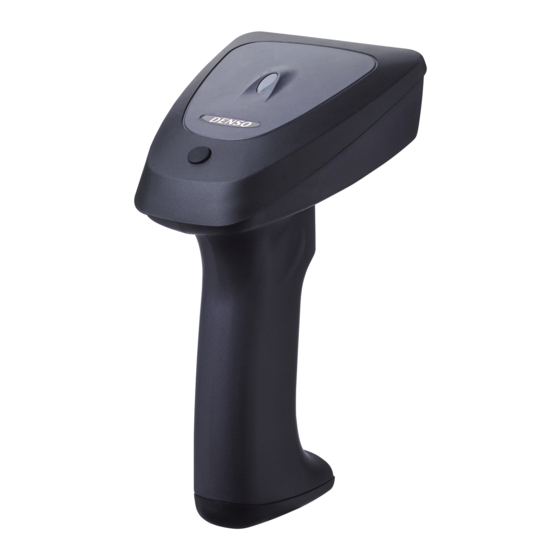
Chapter 1 Parts Names and Functions Indicator LED This turns blue after a successful read and red if there is an error. (Refer to Chapter 10 for details.) Reading window Bring this at the bar code to read. Magic key This acts as an auxiliary key for scans and data transfers. -
Page 11: Chapter 2 Preparation
OS-supplied device driver USB-COM device driver provided by DENSO WAVE Note: The scanner cannot be used on Windows NT that does not support any USB device. * The configuration software (ScannerSetting) is available as free downloads from our website at... -
Page 12: Connecting The Interface Cable To The Scanner
2.2 Connecting the Interface Cable to the Scanner (1) Pull the connector cover of the interface cable off its connector as shown below. (2) Plug the interface cable connector into the connector located in the bottom of the scanner. Note: As shown below, hold the scanner body, align the mark on the cable connector with that on the scanner, and fully insert the interface cable connector. -
Page 13: Chapter 3 Connection To The Host Computer-Setting Up The Usb Interface
Chapter 3 Connection to the Host Computer—Setting up the USB Interface— The scanner receives and sends data from/to the host computer through the USB keyboard interface or USB-COM interface. You need to set up the device driver designed for the interface to be used. Notes for connecting the USB interface cable When plugging and unplugging the USB connector, put an interval of at least 10 seconds between those actions since Windows may take several to 10 seconds to add or delete the USB device. - Page 14 (4) Select the "Display a list of all the drivers in a specific location, so you can select the driver you want." and click Next. (5) The following screen appears. Select "USB Human Interface Device" and click Next. (6) When the following screen appears, click Next.
- Page 15 (7) When the following screen appears, click Finish to return to Windows. (8) To check whether the USB device is working normally, open the Windows’ Device Manager. If USB Human Interface Device is added to the sub-tree of Human Interface Devices as shown below, the scanner is connected normally.
- Page 16 New Hardware Found wizard starts. (3) Wait for a moment. Windows will automatically configure the scanner. Upon completion of installation, the finish screen appears instead of the screen above. Click Finish to return to Windows. (4) To check whether the USB device is working normally, open the Windows’ Device Manager. If USB Human Interface Device is added to the sub-tree of Human Interface Devices as shown below, the scanner is connected normally.
- Page 17 (4) To check whether the USB device is working normally, open the Windows’ Device Manager. If USB Human Interface Device is added to the sub-tree of Human Interface Devices as shown below, the scanner is connected normally. If the device is not added or it is marked with , remove this driver with the uninstaller, reboot your computer, and perform the above connection process again.
-
Page 18: Setting Up The Usb-Com Interface
Note that before the removal, you should confirm that the currently installed USB device driver is not used for other USB devices. If you are using any DENSO WAVE USB device operated by our USB-COM device driver, no driver installation is required since the USB-COM device driver already installed on your computer will be automatically used. - Page 19 Windows device manager is opened. Remove the wrong device with the following steps: 1) Remove DENSO WAVE USB-COM Port from the device manager. 2) Remove the following files if any at the following locations: C: Windows Inf Other DENSO WAVEdwcom.inf...
- Page 20 Windows 98SE (1) Switch the computer on to run Windows 98SE. (2) Connect the scanner to the computer or USB hub. (3) The Add New Hardware Wizard starts. Click Next to proceed. (4) Select Search for the best driver for your device (Recommended), then click Next. (5) Select the Specify a location check box, specify the WIN9X folder in a folder where the downloaded file has been extracted, and then click Next.
- Page 21 (6) If "DENSO WAVE USB-COM Port" is found as "The updated driver (Recommended)", then click Next. (7) If the following screen appears showing that Windows is now ready to install the best driver for the DENSO WAVE USB-COM Port, then click Next.
- Page 22 (9) To make sure that the USB-COM device driver has been successfully installed, open the Windows’ Device Manager. If DENSO WAVE USB-COM Port is added to the sub-tree of Ports (COM & LPT) as shown below, the scanner is connected normally.
- Page 23 Note: The sample window below shows that the downloaded file is stored and extracted in the C: DNWA USBCOM folder. Specify the appropriate folder in your computer instead of C: DNWA USBCOM. (5) If the following screen appears showing that Windows is now ready to install the best driver for the DENSO WAVE USB-COM Port, then click Next.
- Page 24 (7) To make sure that the USB-COM device driver has been successfully installed, open the Windows’ Device Manager. If DENSO WAVE USB-COM Port is added to the sub-tree of Ports (COM & LPT) as shown below, the scanner is connected normally.
- Page 25 The Found New Hardware Wizard starts. (3) Click Next to proceed. (4) Select Search for a suitable driver for my device (recommended), then click Next. (5) Select the Specify a location check box, then click Next.
- Page 26 (6) Specify the WIN2K folder in a folder where the downloaded file has been extracted, and then click OK. Note: Do not specify any folder other than the WIN2K. Doing so might affect the system. Note: The sample window below shows that the downloaded file is stored and extracted in the C: DNWA USBCOM folder.
- Page 27 (10) To make sure that the USB-COM device driver has been successfully installed, open the Windows’ Device Manager. If DENSO WAVE USB-COM Port is added to the sub-tree of Ports (COM & LPT) as shown below, the scanner is connected normally.
- Page 28 The Found New Hardware Wizard starts. (3) Select Install from a list or specific location (Advanced), then click Next. (4) Select Search for the best driver in these locations and the Include this location in the search check box, then specify the WIN2K folder in a folder where the downloaded file has been extracted, and then click Next.
- Page 29 (8) To make sure that the USB-COM device driver has been successfully installed, open the Windows’ Device Manager. If DENSO WAVE USB-COM Port is added to the sub-tree of Ports (COM & LPT) as shown below, the scanner is connected normally.
-
Page 30: Chapter 4 Reading Bar Codes
Note: The effective scan range is less than the full beam sweep. The effective scan range depends on the model and the distance from the scanner to the target. GT10B-SU/GT11B-SU: approximately 10 cm (3.94") for a scan distance of 7 cm (2.76") GT10B-LU: approximately 17 cm (6.69") for a scan distance of 18 cm (7.09") -
Page 31: Chapter 5 Customizing The Scanner
The configuration software also offers batch-process bar code printouts for ready by scanners in the field. Those printouts can be scanned via either of the USB-COM interface or USB keyboard interface. * The configuration software (ScannerSetting) is available as free downloads from our website at http://www.denso-wave.com/. -
Page 32: Chapter 6 Scanning Control
Chapter 6 Scanning Control Two types of scanning controls are available--Trigger switch control and Software control. Trigger switch control: Pressing the trigger switch readies the scanner for scanning. Software control: Instead of pressing the trigger switch, you send control commands from the host computer via the USB-COM interface to ready the scanner for scanning or put the scanner on standby. -
Page 33: Software Control
6.2 Software Control You can control the scanner by sending scanning control commands from the host computer via the USB-COM interface, instead of pressing the trigger switch. Scanning control commands include R, READON, LON, RC, Z, READOFF and LOFF and they are restricted by the trigger switch operating mode, as listed below. - Page 34 Failure read • Auto-off mode 1 Ready-to-scan command Command input (RxD) Bar code 1 to 5 sec. Illumination LEDs Failure notification Data output (TxD) • Momentary switching mode 1 Ready-to-scan command Command input (RxD) Standby command Bar code Illumination LEDs Failure notification Data output (TxD) (2) Continuous reading mode...
-
Page 35: Auto Sensing Mode-Automatic Detection Of Labels
6.3 Auto Sensing Mode—Automatic Detection of Labels In auto sensing mode, bringing a code label within the scan range of the reading window turns on the illumination LED and starts the scanner reading the bar code. No trigger switch operation is required. Use this mode when the scanner is stationary to a stand and a bar code label is moved. -
Page 36: Chapter 7 Magic Key Control
Chapter 7 Magic Key Control The magic key can act as an auxiliary key for scanning or data transfer. You can assign any of the following four functions or no function at all to the magic key. Select the function that best meets your needs using the bar-coded parameter menu or the configuration software (ScannerSetting). -
Page 37: Chapter 8 Scanning Functions
Chapter 8 Scanning Functions 8.1 Data Verification Mode The data verification mode verifies the bar code data read against the master data stored in the scanner and reports the match status with data output. The verification parameters can be set using the bar-coded parameter menu or configuration software (ScannerSetting). After setting them, scan a master bar code, and the scanner becomes capable of data verification read. -
Page 38: Verification Conditions
8.1.2 Verification conditions You can specify a verification starting position and the number of characters to check. • Starting position: The choices are 1st through 7th characters. • Number of characters: The choices are 1 through 7 and everything following the starting position (up to a maximum of 32 characters). -
Page 39: Verification Result Output
8.1.3 Verification result output (1) Report of match/mismatch status You can select any of the following report types by using the bar-coded parameter menu or configuration software (ScannerSetting). Selecting "Disable transmission" reports nothing. Setting If there is a match: If there is a mismatch: Disable transmission. -
Page 40: Specifying The Numbers Of Digits Of Standard 2Of5 And Interleaved 2Of5 Symbols To Read, By Scanning Bar Codes
Specifying the Numbers of Digits of Standard 2of5 and Interleaved 2of5 Symbols to Read, by Scanning Bar Codes You can specify the numbers of digits of Standard 2of5 and Interleaved 2of5 symbols to read. First enable the parameter "specification of the number of digits by bar code scanning" by using the bar-coded parameter menu or configuration software. -
Page 41: Chapter 9 Data Editing
Chapter 9 Data Editing The scanner can edit bar code data read in the format specified with the configuration software (ScannerSetting) and transfer it to the host computer. The format specification parameters retain their settings until the configuration software (ScannerSetting) or bar-coded parameter menu sets "All defaults."... -
Page 42: Substituting Data
(3) Extracting data from the specified start to tail positions The start position must be within the range from the 2nd to 99th digits. If the number of digits in bar code data read does not reach the specified start position, an error occurs. (Example) Start position Output data... -
Page 43: Blocksorting Data
(2) Transferring the substituted element string If the bar code data contains the specified substitution string within the specified search area, the scanner transfers the substituted element string followed by the bar code data read. (Example) Search start position Search string Substitution string Output data 2nd position... -
Page 44: Parenthesizing Ais (Application Identifier) In Ean-128 Data
Parenthesizing AIs (Application Identifier) in EAN-128 Data The scanner parenthesizes all AIs contained in EAN-128 data read and transfers the data. The following sample bar code and scanner settings output data with AIs parenthesized as listed below. - Bar code sample Bar code type: EAN-128, Data read: 0194901234567894110308081303081017040208 - Scanner settings Header: STX, Terminator: ETX, Prefix/Suffix: None, Code ID mark: Type 1,... -
Page 45: Data Editing Notes
(3) Tab (ASCII 09H (HT)) Specifying a tab as a delimiter outputs tab-delimited data. No tab follows the tail of the data. A header and terminator are added to the full string. A prefix, suffix, the number of digits, and code ID mark can be also added to the full string if their transmissions are enabled. -
Page 46: Application Identifier Standards
(12) Conversions apply to Codabar start/stop characters and include them in the number of digits. (13) Conversions force Codabar start/stop characters, if included in the output, to lower case. (14) Conversions skip Code 39 start/stop characters and do not include them in the number of digits. (15) The output never contains Code 39 start/stop characters regardless of their settings. -
Page 47: Chapter 10 Beeper, Indicator Led And Vibrator
Chapter 10 Beeper, Indicator LED and Vibrator 10.1 Beeper (1) Beeping The scanner emits a short or long beep to indicate the scanner status as described below. You can disable the beeper with the bar-coded parameter menu or configuration software (ScannerSetting). The beeper emits a short beep (60 ms, 80 ms, or 120 ms selectable*) when: •... -
Page 48: Indicator Led
10.2 Indicator LED The indicator LED lights or flashes in blue, green or red to indicate the scanner status as described below. The indicator LED lights in blue when: • the scanner has read a bar code successfully, or • bar code data read matches the master bar code data in the data verification mode. The indicator LED lights in green when: •... -
Page 49: Chapter 11 Communication
Chapter 11 Communication The scanner is compliant with USB 1.1 (Universal Serial Bus Specification, Revision 1.1). 11.1 USB Keyboard Interface The USB keyboard interface requires no dedicated device driver. Data read by the scanner can be entered to the cursor position in your application. -
Page 50: Communication Format
(1) Communications protocol You can select either non-acknowledge mode or ACK/NAK mode. Non-acknowledge mode (default) If the CTS signal is at a high level (Enable transmission), the scanner transmits bar code data read. Note: The configuration software provides CTS timeout settings from 100 ms to 9.9 s in 0.1-second increments. Note: The time length required from the issue of the RTS output level change request at the host computer to the detection of the CTS input level change at the scanner may vary depending upon the processing capability and conditions of the host computer. - Page 51 You can also select whether or not to transmit the code ID mark. (Default: No transmission) Code ID mark Bar code systems Type 1 Type 2 Type 5 Type 3 Type 4 (DENSO 1) (DENSO 2) (AIM)* UPC-A UPC-E EAN-13 EAN-8 UPC-A with 2-digit add-on...
- Page 52 (4) Number of digits This optional field specifies the number of digits of bar code data. There is a choice of lengths: two or four digits. Note that UPC and EAN codes (except EAN-128) skip this field. You can also select whether or not to transmit the number of digits. n1 : thousands (0 to 9) n2 : hundreds (0 to 9) n3 : tens (0 to 9)
- Page 53 Codabar (NW-7) Start code Data Stop code The bar code symbology may or may not contain a check digit. You can select whether or not to read a check digit and transmit the check digit read. There are two check digit methods available: modulo arithmetic-16 (MOD-16) and -7 (MOD-7).
-
Page 54: Chapter 12 Parameters And Defaults
Chapter 12 Parameters and Defaults The tables below list the parameters and their defaults. Those parameter settings can be changed with the bar-coded parameter menu and configuration software (ScannerSetting), except shadowed ones only with the configuration software. When the scanner leaves the factory, all of these parameters are set to defaults. (1) Interface to the host Items Parameters... - Page 55 Items Parameters Defaults Refer to: √ None CR LF Header ENTER Right Ctrl ← ↑ → ↓ User-defined Section 11.3 (1) None CR LF Terminator √ ENTER Right Ctrl ← ↑ → ↓ User-defined : Can be changed only with the configuration software.
- Page 56 Transmission of code ID mark √ Disable Before prefix Code ID mark position √ After prefix √ Type1 (DENSO 1) Section 11.3 (3) Type2 (DENSO 2) Code ID mark Type3 Type4 Type5 (AIM) Enable, in 4 digits Transmission of the number of digits Enable, in 2 digits Section 11.3 (4)
- Page 57 UPC-A/E, EAN-13/8 Items Parameters Defaults Refer to: √ Enable Scanning UPC-A, UPC-E, EAN-13 and EAN-8 Disable Enable Scanning UPC/EAN with 2-digit add-on √ Disable Enable Scanning UPC/EAN with 5-digit add-on √ Disable √ Enable Transmission of the number system character of UPC-A Disable √...
- Page 58 Standard 2of5 Items Parameters Defaults Refer to: Enable, without C/D Scanning Standard 2of5 Enable, with C/D √ Disable Minimum number of digits readable 3 digits for Standard 2of5 1 to 99 digits (See Note 3.) Maximum number of digits readable 99 digits for Standard 2of5 √...
- Page 59 Item Parameters Defaults Refer to: √ MOD-16 Check digit method for Codabar (NW-7) 7-check method Section 11.3 (5) Transmit a/b/c/d Transmission of start/stop codes Transmit A/B/C/D for Codabar (NW-7) √ Disable Code 39 Item Parameters Defaults Refer to: √ Enable, without C/D Scanning Code 39 Enable, with C/D Disable...
- Page 60 Code128, EAN-128 Items Parameters Defaults Refer to: √ Enable Scanning Code 128 Disable √ Enable Scanning EAN-128 Disable Minimum number of digits readable 1 digit for Code 128 and EAN-128 1 to 99 digits (See Note 3.) (excluding 1-digit C/D) Maximum number of digits readable 99 digits for Code 128 and EAN-128...
- Page 61 (5) Trigger switch control and magic key control Items Parameters Defaults Refer to: Auto-off mode 1 Auto-off mode 2 √ Momentary switch mode 1 Trigger switch control Section 6.1 Momentary switch mode 2 Continuous reading mode Auto sensing mode 1 sec. 2 sec.
- Page 62 (6) Beeper, indicator LED and vibrator Items Parameters Defaults Refer to: √ Enable Beeper Section 10.1 Disable √ Short (60 ms) Beeping time of a short beep Medium (80 ms) Section 10.1 Long (120 ms) √ High Beeper volume Medium Section 10.1 Tone 1 (2.0 kHz) √...
- Page 63 (7) Reading modes Items Parameters Defaults Refer to: √ Regular read mode Scanning modes Data verification mode Disable transmission/ √ Disable transmission Enable bar code data transmission/ Verification result output in data Disable transmission verification mode Enable bar code data transmission/ (Report of match/mismatch status) Enable NG transmission Enable OK transmission/...
- Page 64 Refer to: √ Speed-priority scanning Chapter 3. Speed-/depth-priority scanning (See Note 5.) √ Depth-priority scanning (Note 5) The default is speed-priority scanning for the GT10B-SU/GT11B-SU, and depth-priority scanning for the GT10B-LU. : Can be changed only with the configuration software.
-
Page 65: Chapter 13 Bar-Coded Parameter Menu
Chapter 13 Bar-Coded Parameter Menu 13.1 Parameter Setting Procedure Using the Bar-Coded Parameter Menu Scan the "Start setting" bar code. "Start setting" ↓ Three beeps Scan desired parameter setting bar codes. Scan parameter setting NOTE: When using the bar-coded parameter menu, scan bar codes within three minutes. bar codes. -
Page 66: Bar-Coded Parameter Menu
13.2 Bar-Coded Parameter Menu Menu control (Starting/ending the setting procedure and reverting to defaults) Start setting End setting All defaults The beeper volume and interface items can be set by only scanning the following bar codes. No "Start setting" or "End setting"... - Page 67 Communications conditions for the USB keyboard interface Caps Lock (USB keyboard interface) Select Caps Lock state which matches that of the connected keyboard. Caps Lock OFF (default) Caps Lock ON Keyboard type (USB keyboard interface) Select the keyboard type that is set up in the host computer. U.S.
- Page 68 Header (USB keyboard interface) None (default) CR LF ENTER Right Ctrl ← ↑ → ↓...
- Page 69 Terminator (USB keyboard interface) None CR LF ENTER (default) Right Ctrl ← ↑ → ↓...
- Page 70 Data transmission interval (USB keyboard interface) You can select the data transmission intervals at which the scanner transfers bar code data to the host computer. 3 ms 6 ms 10 ms (default) 16 ms 30 ms 50 ms 100 ms...
- Page 71 Communications conditions for the USB-COM interface Communications protocol (USB-COM interface) Non-acknowledge mode (default) ACK/NAK mode CTS signal monitor (USB-COM interface) Enable Disable (Default) Header (USB-COM interface) None (default) Terminator (USB-COM interface) CR (default) CR LF...
- Page 72 Disable (default) Code ID mark position Before prefix After prefix (default) Code ID mark Type 1 (DENSO 1) (default) Type 2 (DENSO 2) Type 3 Type 4 Type 5 (AIM) Transmission of the number of digits (not applicable to UPC/EAN codes)
- Page 73 UPC-A/-E and EAN-13/-8 Scanning UPC-A, UPC-E, EAN-13 and EAN-8 Enable (default) Disable Scanning UPC/EAN with Add-on Enable, no restriction on add-on digits Enable 5-digit add-on only Enable 2-digit add-on only Disable (default) Transmission of the number system character of UPC-A Enable (default) Disable Transmission of the number system character of UPC-E...
- Page 74 Transmission of the pad character "0" for the specified number of digits of UPC-E Enable Disable (default) Transmission of a check digit for UPC-A Enable (default) Disable Transmission of a check digit for UPC-E Enable (default) Disable Transmission of a check digit for EAN-13 Enable (default) Disable Transmission of a check digit for EAN-8...
- Page 75 Transmission format of EAN-8 (Conversion to EAN-13) Disable conversion (default) Enable conversion Transmission format of UPC-E (Conversion to UPC-A) Enable conversion (ZERO suppression format) (default) Disable conversion (ZERO insertion format) Transmission of country code for EAN-13 Enable (default) Disable Conversion to ISBN/ISSN format for EAN-13 Enable Disable (default) Standard 2of5...
- Page 76 Transmission of a check digit for Standard 2of5 Enable (default) Disable Specification of the number of digits for Standard 2of5, by bar code scanning Enable Disable (default) Interleaved 2of5 Scanning Interleaved 2of5 Enable, without C/D (default) Enable, with C/D Disable Transmission of a check digit for Interleaved 2of5 Enable (default) Disable...
- Page 77 Codabar (NW-7) Scanning Codabar (NW-7) Enable, without C/D (default) Enable, with C/D Disable Transmission of a check digit for Codabar (NW-7) Enable (default) Disable Calculation method for a check digit of Codabar (NW-7) MOD-16 (default) 7-check method Transmission of start/stop codes for Codabar (NW-7) Transmit a/b/c/d Transmit A/B/C/D Disable (default)
- Page 78 Code 39 Scanning Code 39 Enable, without C/D (default) Enable, with C/D Disable Transmission of a check digit for Code 39 Enable (default) Disable Transmission of start/stop codes for Code 39 Enable Disable (default) Conversion to Full ASCII for Code 39 Enable Disable (default) Code 93...
- Page 79 Code 128/EAN-128 Scanning Code 128 Enable (default) Disable Scanning EAN-128 Enable (default) Disable Transmission of FNC1 for Code 128 and EAN-128 Transmit GS (default) Disable Scanning MSI Enable Disable (default) Plessey Scanning Plessey Enable Disable (default)
- Page 80 GTIN Conversion to GTIN Enable Disable (default) Trigger switch control and magic key control Trigger switch control Auto-off mode 1 Auto-off mode 2 Momentary switching mode 1 (default) Momentary switching mode 2 Continuous reading mode Auto sensing mode Magic key control Illumination switching function Data retransfer function Specific character transfer function...
- Page 81 Scanner sensibility level in auto sensing mode High Medium (default) Beeper, indicator LED and vibrator Beeper Enable (default) Disable Trigger timing for the reading completion beeper and indicator LED Before data transmission (default) After data transmission Indicator LED Enable (default) Disable Vibrator OK vibrations (default)
- Page 82 Reading modes (Regular read mode and data verification mode) Data verification mode Regular read mode (default) Data verification mode Verification result output in data verification mode (Report of match/mismatch status) Disable/Disable (default) Enable bar code data transmission/Disable Enable bar code data transmission/Enable NG transmission Enable OK transmission/Enable NG transmission Verification start position in data verification mode 1st character (default)
- Page 83 Number of characters to verify, starting from the verification start position 1 character 2 characters 3 characters 4 characters 5 characters 6 characters 7 characters Not specified (default) Scan lock in data verification read Enable Disable (default) Notification of a scanning failure that occurred under software control Enable CAN transmission (default) Enable ERROR transmission Disable transmission...
-
Page 84: Chapter 14 Troubleshooting
Chapter 14 Troubleshooting Problem 1: Low reading efficiency. Probable cause What to do: • • A target bar code is not within the scan range of Bring a bar code within the scan range. the reading window. (See Chapter 3.) •... -
Page 85: Appendix 1 Specifications
EAN-13, EAN-8, UPC-A, UPC-E, UPC/EAN with add-on, Interleaved 2of5, Standard 2of5, Code 39, Codabar (NW-7), Code 93, Code 128, EAN-128, MSI, and Plessey Scanning direction Bidirectional Scanning resolution GT10B-SU/GT11B-SU: 4.9 mils (0.125 mm) GT10B-LU: 7.5 mils (0.19 mm) ±40° (∗ Elevation angle (skew) ±20° (∗... - Page 86 Reading diagrams GT10B-SU/GT11B-SU Speed-priority scanning Depth-priority scanning...
- Page 87 Reading diagrams GT10B-LU Speed-priority scanning Depth-priority scanning...
-
Page 88: Appendix 2 Bar Code Sample Label
Appendix 2 Bar Code Sample Label 031323120786 UPC-A 4906906 UPC-E 4901567014010 EAN-13 49400397 EAN-8 0440238 UPC-E with 2-digit add-on 9780330290951 90000 EAN-13 with 5-digit add-on 0123457 Standard 2of5 0123456784 Interleaved 2of 5 b-$:/0B Codabar (NW-7) *TESTE* Code 39 1G1AZ37 Code 93... - Page 89 121347 Code 128 11970 EAN-128 1234558 98765C9 Plessey...
- Page 90 Bar Code Handy Scanner GT10B-SU / GT11B-SU GT10B-LU User's Manual First Edition, February 2004 Fourth Edition, August 2005 DENSO WAVE INCORPORATED...
- Page 91 DENSO WAVE INCORPORATED 4-2-12, Toranomon, Minato-ku, Tokyo, Japan 105-0001 http://www.denso-wave.com/...