Table of Contents
Advertisement
Quick Links
Advertisement
Chapters
Table of Contents

Related Manuals for Denso BHT-6000


Summary of Contents for Denso BHT-6000
- Page 1 User's Manual...
- Page 2 , and QuickBASIC are registered trademarks of Microsoft Cor- poration. ® ® ® , PC/AT , and PS/2 are registered trademarks of International Business Ma- chines Corporation. BHT, CU, BHT-protocol, BHT-Ir protocol, and BHT-BASIC 3.0 are trademarks of DENSO CORPORATION.
- Page 3 After you have finished reading the instructions, keep this manual handy for speedy reference. The BHT-6000 series is available in two types: the normal-range type and long-range type (BHT-6000D). In this manual, both types are called the BHT-6000 unless otherwise...
- Page 4 This manual is made up of five chapters and appendices. Chapter 1. Quick Guide Describes the basic operating method of the BHT-6000 and the related notes. Chapter 2. Getting Started the BHT-6000 and System Mode Summarizes the BHT-6000 system configuration and describes the operation including preparation and System Mode (which is required for the efficient use of application programs).
-
Page 5: Related Publications
■ Related Publications BHT-BASIC 3.0 Programmer's Manual Transfer Utility Guide Ir-Transfer Utility C Guide ■ Screen Indication The lettering in the screens in this manual is a little different from that in the actual screens. File names used are only for description purpose, so they will not appear if you have not set files having those names. -
Page 6: Safety Precautions
SAFETY PRECAUTIONS Be sure to observe all these safety precautions. ■ Please READ through this manual carefully. It will enable you to use the BHT-6000 and CU-6000 correctly. ■ Always keep this manual nearby for speedy reference. Strict observance of these warning and caution indications are a MUST for preventing accidents which could result in bodily injury and substantial property damage. - Page 7 Handling the battery cartridge • Never disassemble or heat the battery cartridge, nor put it into fire or water; doing so could cause battery-rupture or leakage of battery fluid, resulting in a fire or bodily injury. • Do not carry or store the battery car- tridge together with metallic ball-point pens, necklaces, coins, hairpins, etc.
- Page 8 Handling the CU • If smoke, abnormal odors or noises come from the CU, immediately turn off the power, unplug the AC adapter from the wall socket, and contact your nearest dealer. Failure to do so could cause fire or electrical shock. •...
- Page 9 Basic handling tips • Never put the BHT in places where there are excessively high temperatures, such as inside closed-up automobiles, or in places exposed to direct sunlight. Doing so could affect the housing or parts, resulting in a fire. •...
- Page 10 • If you drop the BHT so as to damage its hous- ing, immediately turn off the power, pull out the dry batteries or the battery cartridge, and contact your nearest dealer. Failure to do so could cause smoke or fire. •...
- Page 11 DENSO WAVE INCORPORATED ("DENSO WAVE") takes reasonable precautions to ensure its products do not infringe upon any patent of other intellectual property rights of other(s), but DENSO WAVE cannot be responsible for any patent or other intellectual property right infringement(s) or violation(s) which arise from (i) the...
- Page 12 Blow the particles away with an air brush or a soft brush. ■ Limited Warranty on Software Products In no event will DENSO WAVE be liable for direct, indirect, special, incidental, or consequential damages (including imaginary profits or damages resulting from inter-...
- Page 13 Using the Hand Strap and Clip ... Setting the Backlight ... Using the Keypad ... Communicating via the Optical Interface ... Chapter 2. Getting Started the BHT-6000 and System Mode ... BHT-6000 System Configuration ... Infrared Communications ... 13 Components and Functions ... 14 Preparation ...
-
Page 14: Table Of Contents
5.4.3 Interfacing with the Host Computer ... 138 Charging the Ni-MH Battery Cartridge (using the CU-6001) ... 139 5.5.1 Ni-MH Battery Cartridge Loaded in the BHT-6000 ... 139 5.5.2 Ni-MH Battery Cartridge Alone ... 141 RS-232C Interface Specifications ... 144 Appendices ... - Page 15 Chapter 1. Quick Guide Chapter 2. Getting Started the BHT-6000 and System Mode Chapter 3. Communications Operations of BHT-6000 Chapter 4. Error Messages Chapter 5. Handling the CU-6000 (Option) Appendices...
-
Page 16: Chapter 1. Quick Guide
This chapter describes the basic operating method of the BHT-6000 and the related notes. Reading Bar Codes ... 2 Using the Hand Strap and Clip ... 3 Setting the Backlight ... 4 Using the Keypad ... 5 Communicating via the Optical Interface ... 6 Chapter 1. -
Page 17: Reading Bar Codes
Turn on the BHT power, bring the bar-code reading window up to the bar code to be scanned, and press the M1 or M2 key (Magic key 1 or 2)*. The BHT-6000 lights the illumination LED and reads the bar code. -
Page 18: Using The Hand Strap And Clip
1.2 Using the Hand Strap and Clip Using the hand strap As shown below, set the hand strap, and then put your hand through the hand strap and hold the BHT-6000. This will prevent you from dropping the BHT-6000 acciden- tally. Hand strap... -
Page 19: Setting The Backlight
1.3 Setting the Backlight Pressing the M1 key while holding down SF (Shift) key activates or deactivates the backlight function. A B C D E F G H I J K L M N O P Q R S T U V W X Y Z Sp + - *... -
Page 20: Using The Keypad
2 key for NO response. Entering Alphabetic Characters The BHT-6000 supports the alphabet input function which allows you to enter alpha- betic characters, space, and symbols from the keypad during execution of a user program. For the alphabet input procedure, refer to Appendix C. -
Page 21: Communicating Via The Optical Interface
If transfer using the BHT-6000 fails, bring it closer to the target station or change the IR port angle, and try again. -
Page 22: Chapter 2. Getting Started The Bht-6000 And System Mode
Setting-up 1: Loading Dry Batteries or Battery Cartridge ... 16 2.4.2 Setting-up 2: Initializing the BHT-6000 and Setting the Calendar Clock ... 21 [ 1 ] Initializing the BHT-6000 ... 21 [ 2 ] Setting the Calendar Clock (date and time) ... 24 [ 3 ] Deleting the JIS Font Files ... -
Page 23: Bht-6000 System Configuration
2.1 BHT-6000 System Configuration The BHT-6000 barcode data collection system requires the following hardware as well as the BHT-6000 Bar Code Handy Terminal (which reads bar codes and accepts keypad entry) as illustrated below: • Host computer: For host computers without IrDA interface ports, the optional CU-6000 optical commu- nications unit and RS-232C interface cable are available. - Page 24 The CU-6000 is an IrDA-compliant communications unit which is required when your host computer is not equipped with an IrDA interface port. The CU-6000 exchanges data and programs with the BHT-6000 optically, and with the host computer via the RS-232C interface cable.
- Page 25 Transfer Utility (option) Running on the host computer, this utility transfers files between the BHT-6000 and the host computer. It uses the BHT-protocol as a file transfer control procedure. (For the details about the BHT-protocol, refer to Chapter 3, Subsection 3.3.1.)
- Page 26 System Programs The system programs include the following three sets of programs: Drivers Drivers is a set of programs that directly controls the BHT-6000 hardware. It may be called up by the BHT-BASIC 3.0 Interpreter or System Mode. BHT-BASIC 3.0 Interpreter The interpreter interprets and executes instructions in user programs written in BHT- BASIC 3.0.
- Page 27 These files contain font data required for displaying Kanji characters on the LCD. The BHT-6000 has no Kanji ROM, so it stores Kanji fonts in the flash ROM. The BHT-6000 can display not only the Kanji characters in the conventional standard- size font (16 dots wide by 16 dots high) but also them in the small-size font (12 dots wide by 12 dots high) in application programs.
-
Page 28: Infrared Communications
2.2 Infrared Communications The BHT-6000 has an integrated infrared (IR) communications device which enables wireless transfer of programs and data between the BHT-6000 and the host computer and between the BHT-6000s, instead of the conventional wire transfer. The IR communications device features the following: •... -
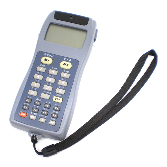
Page 29: Components And Functions
2.3 Components and Functions • Reading confirmation LED Illuminates in green when the BHT has success- fully read the bar codes. • Connector cover Inside this cover is the direct-connect interface port. • Liquid crystal display (LCD) Shows the characters and graphic patterns. - Page 30 • PW (Power) key Turns the BHT-6000 on or off. • BS (Backspace) key Moves back one character. Chapter 2. Getting Started the BHT-6000 and System Mode A B C D E F G H I J K L M N O...
-
Page 31: Preparation
2.4 Preparation 2.4.1 Setting-up 1: Loading Dry Batteries or Battery Before the first use of the BHT-6000, be sure to load dry batteries or battery cartridge as shown below. Dry batteries or battery cartridge is not loaded in the BHT-6000 when shipped from the factory. - Page 32 • Never charge the Ni-MH battery cartridge where • Do not use batteries or power sources other CAUTION Chapter 2. Getting Started the BHT-6000 and System Mode nor put it into fire or water; doing so could cause battery-rupture or leakage of battery fluid, resulting in a fire or bodily injury.
- Page 33 When you first load batteries (or battery cartridge) after purchase or you load them NOTE (it) after leaving the BHT-6000 unused for a long time, do not remove the batteries (battery cartridge) within 24 hours after that loading. Do not leave the BHT-6000 with no batteries or battery cartridge loaded for a long NOTE time.
-
Page 34: Low Battery Indication
• Be sure to put in two new alkaline manganese batteries (LR03). • If the BHT-6000 is not to be used for one month or more, remove the batteries. Upload the data stored in the BHT-6000 memory to the host computer if necessary;... - Page 35 • When driven by the Ni-MH battery cartridge If either of the above messages appears, immediately turn the power off, and then charge the Ni-MH battery cartridge or replace it with a fully charged one. You may charge the Ni-MH battery cartridge with the optional CU-6001 communica- tions unit or C-600 quick charger.
-
Page 36: Setting-Up 2: Initializing The Bht-6000 And Setting The Calendar Clock
In the following cases, one of the above messages will appear. In such in- stances, it is necessary to initialize the BHT-6000. • The BHT-6000 is first powered on from the time of purchase. • The BHT-6000 is powered on after being discharged completely. - Page 37 : Initializes both the flash ROM (ex- cept for its system area) and RAM. This should be chosen when you first power on the BHT-6000 from the time of purchase. 2 DRIVE A : Initializes the RAM only. 3 DRIVE B : Initializes the flash ROM only (ex- cept for its system area).
- Page 38 (DRIVE X)" appears as shown on page 20 although the initialization has com- pleted, initialize the BHT-6000 again. If you initialize the BHT-6000 after downloading user programs and data, all of NOTE those programs and data stored in the target memory area will be lost. Download them again if necessary.
-
Page 39: 2 ] Setting The Calendar Clock (Date And Time)
[ 2 ] Setting the Calendar Clock (date and time) SYSTEM MENU 1:EXEC PROGRAM 2:DOWNLOAD 3:UPLOAD 4:SET SYSTEM 5:TEST 6:VER SET SYSTEM 1:PROGRAM 6:COM 2:DISPLAY 7:KEY 3:DATE/TIME 4:BARCODE 5:RESUME SET DATE/TIME 00/01/01 00:00 While holding down the SF and 1 keys, press the PW key to start System Mode. - Page 40 97/08/19 16:00_ SET DATE/TIME 97/08/19 16:00 Chapter 2. Getting Started the BHT-6000 and System Mode [Example] To set 1997, August 19, at 4:00 p.m. Press 9 , 7 , 0 , 8 , 1 , 9 , 1 , 6 , 0 , and...
-
Page 41: 3 ] Deleting The Jis Font Files
[ 3 ] Deleting the JIS Font Files The JIS Level 1 and Level 2 font files, which are resident in the flash ROM, contain font data for displaying Kanji characters on the LCD. If you do not need to display Kanji characters, you can delete those JIS font files according to the steps below. -
Page 42: Adjusting The Lcd Contrast & Beeper Volume, And Displaying The Battery Voltage Level
After making the above setting, either press the ENT key or press no key for five seconds, and the new setting will be fixed and the above screen will disappear. Chapter 2. Getting Started the BHT-6000 and System Mode LCD CONTRAST... -
Page 43: 2 ] Displaying The Battery Voltage Level
[ 2 ] Displaying the Battery Voltage Level On the SYSTEM MENU or during execution of user programs, press the ENT key while holding down the SF key for displaying the battery voltage level. As long as you hold down those keys, the following screen is displayed. In user programs, you can select the key to be used for displaying the battery REFERENCE voltage level (instead of the default: combination of SF and ENT ). -
Page 44: Operating In System Mode
BHT-6000, which includes various functions as shown on the following pages. 2.5.1 Starting System Mode To start up System Mode, power on the BHT-6000 while holding down the SF and 1 keys. This operation calls up the SYSTEM MENU on the LCD as shown below. - Page 45 (Refer to Subsection 2.5.3, [ 2 ].) Uploading UPLOAD Transfers user program files and data files stored in the RAM or flash ROM of the BHT-6000 to the host computer. (Refer to Subsection 2.5.3, [ 3 ].) System Environment Setting SET SYSTEM 6:COM Sets a variety of environmental condi- tions—an execution program, message...
- Page 46 1:DRIVE A --> B 2:DRIVE B --> A 2 with SF held down Chapter 2. Getting Started the BHT-6000 and System Mode 1 , or 2 key, respectively, while holding SF and 1 keys. Deleting Files DELETE Deletes a program file or data file stored in the RAM or flash ROM.
-
Page 47: Operating In System Mode
2.5.2 Operating in System Mode Some functions in System Mode require several screens to be shifted, as shown in the example below. [ 1 ] Calling up the desired set screen First, select a desired item on the current screen by using the numerical key or the cursor keys ( F5 and F6 ) so as to reverse-display the desired item. -
Page 48: 2 ] Selecting A Desired Setting
( F5 and F6 ) so as to reverse-display the desired item. Use the F7 and F8 keys to select a desired setting and then press the ENT key. The screen returns to the original selection screen. Chapter 2. Getting Started the BHT-6000 and System Mode SET DISPLAY 1:MESSAGE... -
Page 49: Detailed Description Of The Functions In System Mode
2.5.3 Detailed Description of the Functions in System Mode [ 1 ] Program Execution EXECUTE PROGRAM A:SAMPLE01.PD3 A:SAMPLE02.PD3 A:SAMPLE03.PD3 A:SAMPLE04.PD3 B:SAMPLE05.PD3 EXECUTE PROGRAM A:SAMPLE01.PD3 A:SAMPLE02.PD3 A:SAMPLE03.PD3 A:SAMPLE04.PD3 B:SAMPLE05.PD3 ⇓ EXECUTE PROGRAM A:SAMPLE02.PD3 A:SAMPLE03.PD3 A:SAMPLE04.PD3 B:SAMPLE05.PD3 B:SAMPLE06.PD3 ⇓ EXECUTE PROGRAM A:SAMPLE04.PD3 B:SAMPLE05.PD3 B:SAMPLE06.PD3 B:SAMPLE07.PD3... -
Page 50: 2 ] Downloading
Preparation for Copying between the BHTs Before downloading to the BHT-6000 from another BHT-6000, make the fol- lowing preparation: • At each BHT-6000, set the interface port. The default is an optical interface (OPT). Interface setting procedure: Starting on the SYSTEM MENU, select "4:SET SYSTEM,"... - Page 51 Press the C key to return to the DOWNLOAD menu. If the host computer downloads another new file (if the BHT-6000 receives an ENQ code) when this screen is displayed, the BHT-6000 starts receiving (Refer to the "Ir-Transfer Utility C Guide" or "Trans- fer Utility Guide.")
- Page 52 If an error occurs during downloading If some error occurs during downloading, the BHT-6000 beeps three times and shows one of the following screens with the prompt "Retry?": To retry the download, press the 1 and ENT keys; to abort it, press the 2 and ENT keys.
- Page 53 RAM. When receiving downloaded files to the flash NOTE ROM, the BHT-6000 may copy the files stored in the flash ROM into the RAM. This requires an unused user area of 128 kilobytes in the RAM. If there is no area for copying in the RAM, the error message shown at left will appear.
-
Page 54: 3 ] Uploading
(A:) SAMPLE01.PD3 SAMPLE02.PD3 SAMPLE03.PD3 SAMPLE04.PD3 Chapter 2. Getting Started the BHT-6000 and System Mode Selecting "3: UPLOAD" on the SYSTEM MENU calls up the screen shown at left. 1 DRIVE A : Uploads a user program file or data file stored in the RAM . - Page 55 "3:DRIVE A (ALL)" through "5:HT<->HT COPY," then the screen shown at left will appear. Showing this screen, the BHT-6000 waits for a file(s) to be uploaded. Upon start of optional Ir-Transfer Utility C, Trans-...
- Page 56 UPLOAD FILE (A:) XXXXXXXX.XXX Communication error !! Retry? 1:Yes2:No Chapter 2. Getting Started the BHT-6000 and System Mode Problem The file you attempted to upload is damaged. Solution To upload the damaged file as is, press the 1 key. Problem Uploading has failed.
-
Page 57: 4 ] System Environment Setting
[ 4 ] System Environment Setting SET SYSTEM 1:PROGRAM 6:COM 2:DISPLAY 7:KEY 3:DATE/TIME 4:BARCODE 5:RESUME Selecting "4: SET SYSTEM" on the SYSTEM MENU calls up the screen shown at left. 1 PROGRAM : Sets an execution program to be run when the power is turned on. - Page 58 SET EXEC PROGRAM **************** *NO FILE EXISTS* **************** Chapter 2. Getting Started the BHT-6000 and System Mode Selecting "1: PROGRAM" on the SET SYSTEM menu calls up the screen shown at left. Reversed is the current setting. Use the F5 and F6 keys to move the cursor to a desired execution program to be run when the power is applied, and then press the ENT key.
- Page 59 [4.2] Setting the message version, display font size, and system status indication SET DISPLAY 1:MESSAGE Japanese English 2:FONT 8dot 6dot 3:STATUS System Status Indication Turning on the system status indication displays the following icon: Indication Shift state of the keys on the keypad Selecting "2: DISPLAY"...
- Page 60 97/08/19 16:00_ ⇓ SET DATE/TIME 97/08/19 16:00 Chapter 2. Getting Started the BHT-6000 and System Mode Selecting "3: DATE/TIME" on the SET SYSTEM menu calls up the screen shown at left. Use the numerical keys to enter the year (only the last two digits), month, day, hour, and minute in this order, and then press the ENT key.
- Page 61 If "TOUCH READ" is set to OFF, the BHT-6000 can scan bar codes irrespective of the ambient illuminance. This setting, therefore, is suitable for long-range scanning. Note that the scanning speed will slightly decrease.
- Page 62 [4.5] Setting the resume function SET RESUME 1:ON 2:OFF Chapter 2. Getting Started the BHT-6000 and System Mode Selecting "5: RESUME" on the SET SYSTEM menu calls up the screen shown at left. Reversed is the current setting. 1 ON...
- Page 63 [4.6] Setting the communications environments After the BHT-6000 is initialized, the interface port and communications parameters are set as listed in the default table below. Do not access them unless necessary. Interface port Communications protocol Communications parameters for the optical interface port...
- Page 64 [4.6-1] Setting the communications parameters for the optical interface SET OPTICAL 1:TRANSMIT SPEED 2:PULSE WIDTH 3:PROTOCOL Chapter 2. Getting Started the BHT-6000 and System Mode Selecting the "6: COM" on the SET SYSTEM menu calls up the screen shown at left. 1 OPTICAL: Switches to the communi-...
- Page 65 Transmission speed screen SET SPEED < OPTICAL > 1: 2400 4: 38400 2: 9600 5: 57600 3:19200 6:115200 IR beam output pulse width screen SET PULSE WIDTH < OPTICAL > 1:1.63us 2:3/16 Bit Time Communications protocol option menu SET PROTOCOL <...
- Page 66 < OPTICAL > 1:Ignore 2:Data Chapter 2. Getting Started the BHT-6000 and System Mode Selecting the "1:SERIAL No." on the SET PROTO- COL menu calls up the screen shown at left. Select whether or not the system should add serial numbers to data blocks, by using the numerical keys or F5 and F6 keys.
- Page 67 [4.6-2] Setting the communications parameters for the direct-connect interface SET CONNECTOR 1:TRANSMIT SPEED 2:PARITY BIT 3:DATA BIT 4:STOP BIT 5:PROTOCOL (1) Transmission speed screen SET SPEED < CONNECTOR > 1:1200 4: 9600 2:2400 5:19200 3:4800 6:38400 (2) Parity setting screen SET PARITY BIT <...
- Page 68 1:SERIAL No. 2:H.PARITY 3:LINKUP TIME 4:FIELD SPACE Chapter 2. Getting Started the BHT-6000 and System Mode Selecting "3:DATA BIT" on the SET CONNECTOR screen calls up the screen shown at left. Select the desired character length by using the numerical keys or F5 and F6 keys, and then press the ENT key.
- Page 69 SET SERIAL No. < CONNECTOR > 1:ON 2:OFF SET H.PARITY < CONNECTOR > 1:ON 2:OFF SET LINKUP TIME < CONNECTOR > 1:30 4:120 2:60 5:None 3:90 SET FIELD SPACE < CONNECTOR > 1:Ignore 2:Data Selecting the "1:SERIAL No." on the SET PROTO- COL menu calls up the screen shown at left.
- Page 70 [4.6-3] Setting the interface port SET COM PORT 1:BASIC 2:SYSTEM MODE Chapter 2. Getting Started the BHT-6000 and System Mode Selecting the "3:COM PORT" on the SET COM menu calls up the screen shown at left. Reversed is the current setting.
- Page 71 Selecting the "2:BHT IrProtocol" on the PROTO- COL TYPE screen calls up the screen shown at left. Enter the ID number of the BHT-6000 by using the numerical keys, and then press the ENT key. If you do not need to modify the current setting, press the ENT key only.
- Page 72 Defining the function of the shift key SET SHIFT KEY 1:Nonlock 2:Onetime Chapter 2. Getting Started the BHT-6000 and System Mode Selecting the "7:KEY" on the SET SYSTEM menu calls up the screen shown at left. Reversed is the current setting.
- Page 73 Defining the function of M1 or M2 key SET M1 KEY 1:Trigger Switch 2:Shift Key 3:Enter Key 4:Backlight Key 5:None Magic keys M1 and M2 Both M1 and M2 keys are assigned the trigger switch function by default. You can make them function as the SF key, ENT key, or backlight function on/off key.
-
Page 74: 5 ] Testing
5:COMMUNICATION NOTE If an error occurs in any of the above tests, contact your nearest dealer. Chapter 2. Getting Started the BHT-6000 and System Mode Selecting "5: TEST" on the SYSTEM MENU calls up the screen shown at left. 1 BARCODE : Selects the bar-code reading test. - Page 75 CODABAR (NW7) CODE39 CODE93 CODE128 * The BHT-6000 can read only those ITF bar codes hav- ing 4 digits or more in length. Selecting "1: BARCODE" on the TEST menu calls up the screen shown at left. Actually read bar codes with the BHT-6000 and check the read data displayed on the LCD.
- Page 76 TEST MEMORY ** Test OK ** YYYYY/YYYYY Chapter 2. Getting Started the BHT-6000 and System Mode Selecting "2:MEMORY" on the TEST menu calls up the screen shown at left, and then starts writing and reading onto/from all areas of the RAM as well as checking the address.
- Page 77 Selecting "3:BEEPER" on the TEST menu calls up the screen shown at left and makes the beeper sound at three octaves listed below. Upon completion of this test, the BHT-6000 auto- matically returns to the TEST menu. To stop this test while in progress, turn the power off and on.
- Page 78 Arrange two BHT-6000s, one as a master station and the other as a slave station (to be tested) with their IR ports facing each other as illustrated below. In this test, the slave BHT-6000 transmits data to the master BHT-6000 and receives the data sent back from the master BHT-6000.
- Page 79 ** Test OK ** Selecting the "1:OPTICAL" on the TEST COM menu calls up the screen shown at left. At the slave BHT-6000 to be tested, select the "1:SLAVE" and at the master BHT-6000, select the "2:MASTER." During the test, the screen shown at left is dis- played.
- Page 80 TEST COM < CONNECTOR > ** Test OK ** Chapter 2. Getting Started the BHT-6000 and System Mode Selecting the "2:CONNECTOR" on the TEST COM menu displays the screen shown at left and then starts testing the direct-connect interface port.
- Page 81 [5.6] LCD and reading confirmation LED tests ⇑ ⇓ BS key ENT key ⇑ ⇓ BS key ENT key ⇑ ⇓ BS key ENT key ⇑ ⇓ BS key ENT key Selecting "6:LCD" on the TEST menu calls up the test pattern shown at left on the LCD and turns on the reading confirmation LED in green.
- Page 82 `abcdefghijklmno pqrstuvwxyz{|} ⇑ ⇓ After 0.5 second Chapter 2. Getting Started the BHT-6000 and System Mode The fine checker pattern appears. The fine checker pattern is reversed. Two right-angled triangles appear. After showing all of the test patterns, the screen automatically displays symbols, numerals, and al- phabets.
- Page 83 7894561230.= ABCDEFGHIJK Selecting "7:KEY" on the TEST menu calls up the screen shown at left and makes the BHT-6000 ready for entry from the keypad. Pressing individual keys displays the identifier let- ters in the positions preassigned to those keys on the LCD and sounds the beeper.
- Page 84 SAMPLE01.PD3 *SAMPLE02.DAT SAMPLE03.PD3 SAMPLE04.PD3 Chapter 2. Getting Started the BHT-6000 and System Mode Selecting "8: FILE" on the TEST menu calls up the screen shown at left and tests all files stored in the RAM and flash ROM. If the RAM and/or the flash ROM contain any de- fective file(s), an asterisk (*) will be prefixed as "*1: DRIVE A"...
- Page 85 TEST FILE (A:) SAMPLE01.PD3 00004096 bytes TEST FILE (A:) SAMPLE02.PD3 00004096 bytes If a defective file is found, delete it or overwrite it with the same name file. NOTE Even defective, the file can be uploaded on the UPLOAD menu. It is, therefore, recommended that important files be uploaded before deleted.
-
Page 86: 6 ] Version Indication
File deletion menu DELETE 1:DRIVE A 2:DRIVE B Chapter 2. Getting Started the BHT-6000 and System Mode Selecting the “6:VER” on the SYSTEM MENU calls up the screen shown at left, indicating the ver- sions of memory-resident System Program and JIS font files, and the sizes of the RAM and flash ROM. - Page 87 File selection screen DELETE FILE (A:) SAMPLE01.PD3 SAMPLE02.PD3 SAMPLE03.PD3 SAMPLE04.PD3 DELETE FILE (A:) **************** *NO FILE EXISTS* **************** Deletion confirmation screen DELETE FILE (A:) SAMPLE01.PD3 Delete? 1:Yes 2:No Deletion completion screen DELETE FILE (A:) SAMPLE01.PD3 ** Completed ** In the center of the 2nd line appears the selected item--(A:) or (B:).
-
Page 88: 8 ] Copying Files
COPY FILE (A->B) SAMPLE01.PD3 Copy? 1:Yes 2:No Chapter 2. Getting Started the BHT-6000 and System Mode Pressing the key while holding down the SF key on the SYSTEM MENU calls up the screen shown at left. 1 DRIVE A-->DRIVE B :... - Page 89 ** Completed ** If an error occurs during file copying If some error occurs during file copying, the BHT-6000 beeps three times and shows one of the following screens: To return to the file selection screen, press the C key.
-
Page 90: 9 ] Handling The Jis Font Files
Deleting the JIS1/JIS2 font file Deletion menu DELETE 1:JIS 1 2:JIS 2 Chapter 2. Getting Started the BHT-6000 and System Mode Pressing the key while holding down the SF key on the SYSTEM MENU calls up the screen shown at left. - Page 91 Confirmation screen DELETE JIS 1 DELETE OK ? 1:Yes 2:No Deletion completion screen DELETE JIS 1 DELETE ** Completed ** Before deleting the JIS Level 1 or Level 2 font file, be sure to upload it to the host NOTE computer to save it for the future use.
- Page 92 On the 3rd line appears the font file to be downloaded. This example shows that the "1: JIS 1" has been selected. The BHT-6000 is waiting for the selected file to be downloaded. Upon start of optional Ir-Transfer Utility C, Trans-...
- Page 93 In such cases, temporarily upload all of the user files stored in the flash ROM to the host computer, delete those files in the flash ROM, and download the JIS Level 1 and/or Level 2 font files to the BHT-6000. After that, download all of the uploaded user files to the BHT-6000.
- Page 94 2:JIS 2 Standby screen UPLOAD JIS 1 ** Waiting ** Chapter 2. Getting Started the BHT-6000 and System Mode Problem Downloading has failed. Solution To retry downloading, press the 1 key. To return to the SYSTEM MENU, press the 2 key.
- Page 95 YYYYY/YYYYY If an error occurs during uploading of JIS1/JIS2 font file If some error occurs during uploading of the JIS1/JIS2 font file, the BHT-6000 beeps three times and shows one of the following messages: Press the C key to return to the JIS font file upload menu.
-
Page 96: Chapter 3. Communications Operations Of Bht-6000
Communications Operations of BHT-6000 This chapter describes the communications operations of the BHT-6000--the RS-232C interface specifications, the basic communications specifications, and the communica- tions protocols--for data transmission with the host computer or other devices. RS-232C Interface Specifications ... 82 [ 1 ] Interface Connector and Pin Assignment ... 82 [ 2 ] Interface Cable Connection ... -
Page 97: Rs-232C Interface Specifications
NOTE disconnecting. Do not plug and unplug basically more than one time a day; otherwise, the service life of the plug will shorten. To connect the BHT-6000 to a host computer (or another BHT-6000) frequently, use the CU-6000. Allow the specified signals only to enter the direct-connect interface port. Entry of NOTE other signals will result in a failure or malfunction of the BHT-6000. -
Page 98: 2 ] Interface Cable Connection
[ 2 ] Interface Cable Connection Connect the BHT-6000 directly to a host computer, a modem, or a printer with a direct- connect interface cable as illustrated below. BHT-6000 Connector I/F Cable Connection between BHT-6000 and Host Computer BHT-6000 Connector I/F... -
Page 99: Basic Communications Specifications And Parameters
3.2 Basic Communications Specifica- tions and Parameters 3.2.1 Basic Communications Specifications Listed below are the communications specifications when the BHT-6000 exchanges data with a host computer through the CU-6000 (optical interface) or direct-connect interface cable. Synchronization Transmission Speed Transmission Code... - Page 100 Transmission Code and Bit Order All characters should be coded to 7- or 8-bit code for data transmission. The standard data exchange code of the BHT-6000 is JIS 7- or 8-bit code. The transmis- sion bit order is LSB (Least significant bit) first.
-
Page 101: Communications Parameters
3.2.2 Communications Parameters In System Mode and user programs written in BHT-BASIC 3.0, you may set the communications parameters listed below. Communications Port Transmission Speed Character Length Vertical Parity Stop Bit Length In System Mode Refer to Chapter 2, Subsection 2.5.3, "Detailed Description of the Functions in System Mode,"... -
Page 102: Communications Protocols
3.3 Communications Protocols The BHT-6000 supports both the BHT-protocol and the BHT-Ir protocol for file trans- mission. 3.3.1 BHT-protocol [ 1 ] Overview The BHT-protocol is the communications procedure used to transmit files between the BHT-6000 and a host (or between the BHT-6000s). It adopts the response method using ACK/NAK codes. -
Page 103: 2 ] Control Characters
Negative Acknowledge Transparency The BHT-6000 uses the non-transparent mode which handles the control characters and codes (e.g., STX, ETX, and SOH) as starting or ending markers and does not allow them to be transmitted as normal data in the transmission texts. - Page 104 End Of Text You may designate headers and a terminator with the protocol functions in BHT-BASIC 3.0. If you designate none of them in a user program, the BHT-6000 may apply those as listed above. Refer to the "BHT-BASIC 3.0 Programmer's Manual."...
-
Page 105: 3 ] Basic Format Of Transmission Messages
[ 3 ] Basic Format of Transmission Messages Basically, the BHT-6000 transmits data as units of a file. First, it transmits a heading text which includes the attribute information of a file (e.g., file name and the number of data texts) to be transmitted. Following the heading text, it transmits the data text in the file. -
Page 106: 4 ] Transmission Control Sequences
Data Link (Phase 1) Serial number Data Transmission (Phase 2) Serial number Serial number Release of Data Link (Phase 3) Chapter 3. Communications Operations of BHT-6000 Sending Station Heading text Data text 1 Data text n-1 Data text n Receiving Station... - Page 107 Data transmission may accidentally involve various types of errors. The BHT-protocol is designed to recover from those errors as frequently as possible. What follows is the BHT-protocol for phases 1 through 3. Phase 1: Establishment of Data Link Normal phase 1 The sending station transmits an ENQ to the receiving station.
- Page 108 The receiving station's default timeout is 30 seconds. You may modify the timeout length on the SET LINKUP TIME screen in System Mode (p. 51) or by using the XFILE statement (refer to the "BHT-BASIC 3.0 Programmer’s Manual"). Chapter 3. Communications Operations of BHT-6000 Receiving station ENQ(1)
- Page 109 Phase 2: Data Transmission Normal phase 2 The sending station first sends a transmission block containing the heading text. Each time the sending station receives an ACK from the receiving station, it sends a transmission block containing the data texts as shown below. Upon receipt of an ACK in response to the last transmission block (data text n), the sending station shifts to phase 3.
- Page 110 Even if the phase 3 terminates normally, the transmission results in an abnormal end. Sending station Occurrence of an error To phase 3. Chapter 3. Communications Operations of BHT-6000 Receiving Data text m station Data text m Data text m Data text m+1...
- Page 111 Phase 2 with EOT If the sending station receives an EOT anytime during phase 2, it shifts to phase 3 to terminate the message transmission abnormally. Even if the phase 3 terminates normally, the transmission results in an abnormal end. Sending station Occurrence of...
- Page 112 The sending station transmits an EOT to the receiving station. Upon receipt of an ACK from the receiving station, the sending station terminates the message trans- mission normally and releases the data link. Sending station Normal termination Chapter 3. Communications Operations of BHT-6000 Receiving station ENQ (1) ENQ (2) ENQ (9) Receiving...
- Page 113 Phase 3 with iterated EOT transmission due to no response or invalid response If the sending station receives no response or any invalid response from the receiving station in response to an EOT sent, it iterates sending of an EOT at three- second intervals up to ten times.
-
Page 114: 5 ] Aborting Data Transmission
[ 5 ] Aborting Data Transmission Pressing the C key aborts data transmission. If the C key is pressed during downloading, the BHT-6000 transmits an EOT and aborts the file transmission. If it is pressed during uploading, the BHT-6000 transmits the current transmission... -
Page 115: 6 ] Bcc For Horizontal Parity Checking
[ 6 ] BCC for Horizontal Parity Checking To check whether data has been transmitted accurately, the BHT-6000 supports hori- zontal parity checking for every transmission block. In horizontal parity checking, a horizontal parity byte so called BCC (Block Check Character) is suffixed to an ETX of every transmission block. -
Page 116: 7 ] Text Format
Object file (compiled from a source program file having one of the extensions .PD3, .FN3, and .EX3.) Chapter 3. Communications Operations of BHT-6000 4 5 6 7 8 9 10 11 12 13 14 15 16 P D 3... - Page 117 Data Text Format (1) Heading text Byte 1 2 3 4 5 6 7 8 9 10 11 12 13 14 15 16 17 18 19 20 21 position Data file name (12 bytes) Example of M A S T E R contents The data file name should be a maximum of 12 characters in length...
-
Page 118: Bht-Ir Protocol
The BHT-Ir protocol is the communications procedure for the serial infrared link, which is used to transmit files between the BHT-6000 and a host (or between the BHT-6000s). It adopts the response method using ACK/NAK codes. The BHT-Ir protocol can be used also for communications through the direct-connect interface. -
Page 119: 2 ] Control Characters
103Bh Wait for Acknowledge Transparency The BHT-6000 uses the transparent mode which allows the control characters and codes (e.g., STX, ETX, SOH, and DLE) to be transmitted as normal data in the transmission texts. To transmit a DLE as normal data, type DLE DLE per DLE. - Page 120 End Of Text In the BHT-Ir protocol, you cannot change the values of the headers and terminator with the protocol functions in BHT-BASIC 3.0. Chapter 3. Communications Operations of BHT-6000 Function Indicates the start of heading text (Phase Indicates the start of data text (Phase 2).
-
Page 121: 3 ] Basic Format Of Transmission Messages
[ 3 ] Basic Format of Transmission Messages Basically, the BHT-6000 transmits data as units of a file. First, it transmits a heading text which includes the attribute information of a file (e.g., file name and the number of data texts) to be transmitted. Following the heading text, it transmits the data text in the file. -
Page 122: 4 ] Transmission Control Sequences
(Phase 1) • • Data Transmis- sion (Phase 2) • • DLE EOT and IDs Release of Data Link (Phase 3) Chapter 3. Communications Operations of BHT-6000 Heading text • Serial Data text 1 • number Serial Data text n-1 •... - Page 123 Data transmission may accidentally involve various types of errors. The BHT-Ir proto- col is designed to recover from those errors as frequently as possible. What follows is the BHT-Ir protocol for phases 1 through 3. Phase 1: Establishment of Data Link Normal phase 1 The sending station transmits a sequence of DLE ENQ and IDm (sending station’s ID) to the receiving station.
- Page 124 The receiving station's default timeout is 30 seconds. You may modify the timeout length on the SET LINKUP TIME screen in System Mode (p. 51) or by using the XFILE statement (refer to the "BHT-BASIC 3.0 Programmer’s Manual"). Chapter 3. Communications Operations of BHT-6000 Receiving station DLE ENQ and IDm (1)
- Page 125 Phase 2: Data Transmission Normal phase 2 The sending station first sends a transmission block containing the heading text. Each time the sending station receives a sequence of DLE ACK and IDs from the receiving station, it sends a transmission block containing the data texts as shown below.
- Page 126 Phase 2 with suspension of data reception for erasure of the flash ROM If the receiving BHT-6000 requires the flash ROM to be erased for receiving downloaded files, it sends a sequence of WACK and IDs to the sending station to suspend the data transmission.
- Page 127 Phase 2 with a sequence of DLE NAK and IDs If the sending station receives a sequence of DLE NAK and IDs from the receiving station in response to a transmission block containing text data m, it sends that transmission block again immediately as shown below. If the sending station receives a sequence of DLE ACK and IDs before receiving the sequence of DLE NAK and IDs 10 times in succession, it continues the subsequent message transmission.
- Page 128 If the sending station receives a sequence of DLE ACK and IDs before sending the sequence of DLE ENQ and IDs 59 times, it continues the subsequent message transmission. Sending station 0.5 second 0.5 second Chapter 3. Communications Operations of BHT-6000 Receiving station DLE EOT and IDs Receiving station Data text m...
- Page 129 Abnormal termination of phase 2 (Abort of phase 2) If the sending station receives no sequence of DLE ACK and IDs from the receiving station after sending a sequence of DLE ENQ and IDs 59 times in succession, it sends a sequence of DLE EOT and IDs to the receiving station after 0.5 second from the 59th sequence of DLE ENQ and IDs and then aborts this transmission abnor- mally.
- Page 130 Sending station 0.5 second 0.5 second 0.5 second Abnormal termination Chapter 3. Communications Operations of BHT-6000 Receiving DLE EOT and IDs (1) station DLE EOT and IDs (2) DLE EOT and IDs (3) DLE ACK and IDs Receiving...
-
Page 131: 5 ] Aborting Data Transmission
[ 5 ] Aborting Data Transmission Pressing the C key aborts data transmission. If the C key is pressed during downloading, the BHT-6000 transmits a sequence of DLE EOT and IDs and aborts the file transmission. If it is pressed during uploading, the BHT-6000 transmits the current transmission block followed by a sequence of DLE EOT and IDs and then aborts the file transmis- sion. -
Page 132: 6 ] Crc
Any of 0001h through FFFFh is assigned to the BHT- 6000 as follows. • The system sets an ID when the BHT-6000 is initialized. • You may set an arbitrary ID in System Mode or by using the OUT statement in BHT-BASIC 3.0. -
Page 133: 8 ] Text Format
[ 8 ] Text Format Text should be formatted according to the standard of the BHT-Ir protocol before transmission. Shown below are two types of the standard text formats for program files and data files. Program Text Format (1) Heading text Byte position Program file name (12 bytes) - Page 134 250 (50 x 5) bytes and the number of the character count bytes is 5. Accordingly, the total is 255, so you can transfer the file. Chapter 3. Communications Operations of BHT-6000 9 10 11 12 13 14 15 16 17 18 19 20 21...
-
Page 136: Chapter 4. Error Messages
This chapter lists the error messages which will appear on the LCD if some error occurs in the BHT-6000. System Errors ... 122 Errors in System Mode ... 126 Chapter 4. Error Messages Chapter 4 Error Messages... -
Page 137: System Errors
BHT-6000 beeps five times (for 0.1 second per beep). Solution If the BHT-6000 is loaded with dry batteries, imme- diately turn off the power and replace the batter- ies. If the BHT-6000 is loaded with the Ni-MH battery cartridge, immediately turn off the power and then replace or charge the battery cartridge. - Page 138 Flash ROM error Problem The system has failed to write onto the flash ROM. If this error occurs, the BHT-6000 beeps five NOTE times (for 0.1 second per beep) and then turns itself off.
- Page 139 The system has failed to set the date & time to the real time clock RTC (the so-called "calendar clock") or has failed to read out from it. If this error occurs, the BHT-6000 beeps five NOTE times (for 0.1 second per beep) and then turns itself off.
- Page 140 No user program has been selected as an execu- tion program to be run when the power is turned Solution Operate the BHT-6000 in System Mode and select an execution program in the SET SYSTEM menu. (For the selecting procedure, refer to Chapter 2, Subsection 2.5.3, [4.1].)
-
Page 141: Errors In System Mode
4.2 Errors in System Mode If some error occurs during operation in System Mode, one of the following error messages will appear on the LCD. EXECUTE PROGRAM **************** *NO FILE EXISTS* **************** SET EXEC PROGRAM **************** *NO FILE EXISTS* **************** UPLOAD FILE (A:) ****************... - Page 142 DELETE FILE (A:) **************** *NO FILE EXISTS* **************** DOWNLOAD FILE (A:) Out of memory !! Retry? 1:Yes2:No DOWNLOAD FILE (A:) File mismatch !! Retry? 1:Yes2:No Chapter 4. Error Messages Problem You have deleted all of the files stored in the des- ignated memory in the DELETE menu.
- Page 143 RAM. When receiving downloaded files to the flash NOTE ROM, the BHT-6000 may copy the files stored in the flash ROM into the RAM. This requires an unused user area of 128 kilobytes in the RAM. If there is no area for copying in the RAM, the error message shown at left will appear.
- Page 144 JIS1/JIS2 font file, but user programs. • Although the JIS Level 1 font file was already selected on the BHT-6000, the host computer attempted to download the JIS Level 2 font file. Solution Press the C key to return to the SYSTEM MENU.
- Page 145 UPLOAD FILE (A:) SAMPLE00.PD3 File error !! Upload?1:Yes2:No UPLOAD FILE (A:) XXXXXXXX.XXX Communication error !! Retry? 1:Yes2:No UPLOAD JIS 1 Communication error !! Retry? 1:Yes2:No During uploading of a program file or data file Problem The file you attempted to upload is damaged. Solution To upload the damaged file as is, press the 1 key.
- Page 146 COPY FILE (A->B) Out of memory !! COPY FILE (A->B) Too many files!! Chapter 4. Error Messages During file copying Problem The target memory is insufficient for storing files to be copied. Solution Press the C key to return to the SYSTEM MENU, then delete unnecessary files in the memory.
-
Page 148: Chapter 5. Handling The Cu-6000 (Option)
Interfacing with the Host Computer ... 138 Charging the Ni-MH Battery Cartridge (using the CU-6001) ... 139 5.5.1 Ni-MH Battery Cartridge Loaded in the BHT-6000 ... 139 5.5.2 Ni-MH Battery Cartridge Alone ... 141 [ 1 ] Fully Discharging (Refresh) and then Charging ... 142 [ 2 ] Charging Only ... -
Page 149: Functions Of The Cu-6000
(1). Data exchange function The CU-6001/CU-6002 exchanges data and programs between the BHT-6000 and the host computer. It interfaces with the BHT-6000 via the optical interface and with the host computer via the RS-232C interface. Ni-MH battery cartridge charging function The CU-6001 charges the Ni-MH battery cartridge. - Page 150 Shows the status of the CU-6001. POWER LED (green) Lights when the power is applied to the CU-6000. DATA communications LED (green) Lights when the BHT-6000 is communicating with POWER DATA the host computer. CHG2 LED (Battery cartridge charge lamp)
-
Page 151: Applying Power To The Cu-6000
5.3 Applying Power to the CU-6000 Apply power to the CU-6000 by connecting it to the wall socket via the attached AC adapter according to the steps given below. Make sure that the CU-6000 is turned off. Connect the outlet plug of the AC adapter to the power inlet connector of the CU- 6000, then plug the other end of the AC adapter into the wall socket. -
Page 152: Communicating With The Host Computer
5.4.1 Setting the Transmission Speed of the CU-6000 Set the transmission speed of the CU-6000 to the same value as that of the BHT-6000 and the host computer, by using the DIP switch provided on the bottom of the CU- 6000. -
Page 153: Interfacing With The Host Computer
Power on the host computer and start up the MS-DOS. Turn on the power switch of the CU-6000. Make sure that the BHT-6000 is turned off, then put it on the CU-6000. Power on the BHT-6000 and run System Mode. Set the communications environ- ments (communications protocol, interface port, communications parameters, and protocol options). -
Page 154: Charging The Ni-Mh Battery Cartridge (Using The Cu-6001)
5.5 Charging the Ni-MH Battery Car- tridge (using the CU-6001) You may charge Ni-MH battery cartridges either loaded in the BHT-6000 or all by themselves. Service Life of Ni-MH Battery Cartridge: NOTE Ni-MH batteries used in the battery cartridge will gradually deteriorate during the repeated cycles of charging and discharging due to its properties, even under normal use. - Page 155 Charging Operation and LED Indication Operator's Action Power on the CU-6001. ⇓ Place the BHT-6000 on the CU-6001. ⇓ After approx. 10 hours ⇓ Remove the BHT-6000. * "Trickle charging" is a slow continuous charge for a battery, which compensates for the slight amount of discharge happening even when batteries are not in use.
-
Page 156: Ni-Mh Battery Cartridge Alone
5.5.2 Ni-MH Battery Cartridge Alone The CU-6001 can charge Ni-MH battery cartridges in either of the following two ways: - Fully discharging and then charging* - Charging only To select [ 1 ], first power on the CU-6001 and then load a Ni-MH battery cartridge into it. -
Page 157: 1 ] Fully Discharging (Refresh) And Then Charging
[ 1 ] Fully Discharging (Refresh) and then Charging Power on the CU-6001. The POWER LED comes on. Load a Ni-MH battery cartridge into the CU-6001 from the battery cartridge slot. The CU-6001 flashes the CHG2 LED at 0.4-second intervals and starts discharging the cartridge. -
Page 158: 2 ] Charging Only
[ 2 ] Charging Only Load a Ni-MH battery cartridge into the CU-6001 from the battery cartridge slot. Power on the CU-6001. The CU-6001 turns on the CHG2 LED and starts charging the cartridge. After approx. ten hours of charging, the CHG2 LED starts flashing at 2-second intervals, indicating that the charging is completed. -
Page 159: Rs-232C Interface Specifications
5.6 RS-232C Interface Specifications [ 1 ] Interface Connector and Pin Assignment The CU-6000 has an RS-232C interface port (Dsub-25S). RS-232C interface port (Dsub-25S) on the CU-6000 Pin No. Signal Functions Frame ground Send data Receive data Request to send Ready to send Data set ready Signal ground... -
Page 160: 2 ] Interface Cable Connection
The DTE is one piece of equipment connected at both ends of a communications line as a sender or receiver of data (such as CU-6000 joined with the BHT-6000 and a host computer). The DCE is one piece of equipment connected to the intermediate point between the DTE and the communications line. -
Page 162: Appendices
Appendix A. Specifications ... 148 A.1 BHT-6000 ... 148 [ 1 ] Product Specifications ... 148 [ 2 ] Bar Code Specifications ... 149 [ 3 ] Interface Specifications ... 153 A.2 CU-6000 ... 154 [ 1 ] Product Specifications ... 154 [ 2 ] Charging/Discharging Requirements (CU-6001) ... -
Page 163: Appendix A. Specifications
Appendix A. Specifications BHT-6000 [ 1 ] Product Specifications Power Source Main power Backup power Dimensions (W) x (L) x (H) Weight Operating Ambient Temperature Operating Humidity Ambient Illuminance Controller Keypad Display Calendar Clock Reading Confirmation LED • Two alkaline manganese batteries (LR03) •... -
Page 164: 2 ] Bar Code Specifications
[ 2 ] Bar Code Specifications Normal-range Type (1) Available Bar Code Types Bar code type Universal product codes EAN-13 EAN-8 UPC-A UPC-E EAN-13 with supplemental codes EAN-8 with supplemental codes UPC-A with supplemental codes UPC-E with supplemental codes 2-digit add-on 5-digit add-on Interleaved 2 of 5 (ITF) Standard 2 of 5 (STF) - Page 165 (3) Bar Code Label Size Recommended width: 10 mm min. (0.39 inch min.) Length: (Distance from bar codes to the bar-code reading window) 240 mm (9.45 inches) 1 2 3 4 5 6 7 8 9 0 1 2 3 4 5 6 7 8 9 0 1 2 3 4 5 6 7 8 9 0 1 2 1 2 3 4 5 6 7 8 9 0 1 2 3 4 5 6 7 8 9 0 1 2 3 4 5 6 7 8 9 0 1 2 3 4 5 6 7 8 9 0 1 2 1 2 3 4 5 6 7 8 9 0 1 2 3 4 5 6 7 8 9 0 1 2 3 4 5 6 7 8 9 0 1 2 3 4 5 6 7 8 9 0 1 2 1 2 3 4 5 6 7 8 9 0 1 2 3 4 5 6 7 8 9 0 1 2 3 4 5 6 7 8 9 0 1 2 3 4 5 6 7 8 9 0 1 2 1 2 3 4 5 6 7 8 9 0...
- Page 166 Long-range Type (BHT-6000D) (1) Available Bar Code Types Bar code type Universal product codes EAN-13 EAN-8 UPC-A UPC-E EAN-13 with supplemental codes EAN-8 with supplemental codes UPC-A with supplemental codes UPC-E with supplemental codes 2-digit add-on 5-digit add-on Interleaved 2 of 5 (ITF) Standard 2 of 5 (STF) CODABAR (NW7) CODE39...
- Page 167 (3) Bar Code Label Size Recommended width: 10 mm min. (0.39 inch min.) Length: (Distance from bar codes to the bar-code reading window) 68 mm (2.7 inches) 350 mm (13.78 inches) 1 2 3 4 5 6 7 8 9 0 1 2 3 4 5 6 7 8 9 0 1 2 3 4 5 6 7 8 9 0 1 2 1 2 3 4 5 6 7 8 9 0 1 2 3 4 5 6 7 8 9 0 1 2 3 4 5 6 7 8 9 0 1 2 3 4 5 6 7 8 9 0 1 2 1 2 3 4 5 6 7 8 9 0 1 2 3 4 5 6 7 8 9 0 1 2 3 4 5 6 7 8 9 0 1 2 3 4 5 6 7 8 9 0 1 2 1 2 3 4 5 6 7 8 9 0 1 2 3 4 5 6 7 8 9 0 1 2 3 4 5 6 7 8 9 0 1 2 3 4 5 6 7 8 9 0 1 2 1 2 3 4 5 6 7 8 9 0...
-
Page 168: 3 ] Interface Specifications
Pin assignment: Pin No. Signal Functions SG (GND) Ground for signals Send data Receive data Start-stop 115200 bps max. Start-stop 38400 bps max. Conforms to the RS-232C interface As shown below. Appendices Signal Input/Output External BHT-6000 device — → ←... -
Page 169: 1 ] Product Specifications
(W) x (L) x (H) Weight Operating Ambient Temperature Operating Humidity [ 2 ] Charging/Discharging Requirements (CU-6001) For charging a Ni-MH battery cartridge loaded in the BHT-6000 Charge current: Charge time: For charging a Ni-MH battery cartridge all by itself Charge current:... -
Page 170: 3 ] Interface Specifications
Shown below is a diagram of the internal connection in the CU-6000. Host computer, modem, or other devices Signal Pin No. Name Not used. CU-6000 Optical RS-232C Communications Interface Interface Circuitry Circuitry Appendices Signal Input/Output External CU-6000 device — → ← — — — — — Optical Interface BHT-6000... -
Page 171: Appendix B. A Typical Basic Operation
Appendix B. A Typical Basic Operation What follows is a typical basic operation which helps you instruct the hands-on user in practical bar-code reading operation. Application type: Inventory Operation: Power ON → Read the bar code on stock (A). → Key in the quantity. 2. -
Page 172: Appendix C. Alphabet Input Procedure
Appendix C. Alphabet Input Procedure To activated or deactivate the alphabet input func- tion, issue statement in a user program. As shown at right, each of 0-9 numerical keys and period key is assigned three characters. For exam- ple, the 7 key is assigned A, B, and C. To designate one of three assigned characters, use the M1 or M2 key. - Page 173 • For displaying the shift guidance block Right when the status indication is set to ON, the BHT-6000 overwrites the status indication with the shift block. • The activated or deactivated state of the alphabet input function will be re-...
-
Page 174: Index
Symbols 25-pin plug (Dsub-25P) 3-pole mini stereo plug 9, 35, 63, 82 AC adapter vi, viii, ix, 134, 136, 154 aging test 30, 59, 62 backlight 4, 15, 58, 148 backlight function 4, 15, 58 backlight function on/off key bar-code reading test 30, 59, 60 batteries v, vii, viii, 14, 17, 18, 19, 20,... - Page 175 DATA communications LED decode level defective file 69, 70, 124 deleting file 31, 71 DIP switch direct-connect interface, direct-connect interface port 9, 10, 14, 35, 48, 49, 52, 55, 63, 65, 82, 83, 84, 86, 103, 153 download, downloading 8, 9, 10, 11, 12, 23, 30, 31, 35, 36, 37, 38, 39, 55, 56, 75, 77, 78, 79, 99, 111, 116, 124, 126, 127, 128, 129, 138...
- Page 176 key entry & beeper test 59, 68 LCD and reading confirmation LED tests 59, 66 LCD contrast 7, 19, 23, 27, 44 lithium battery 10, 18, 148 long-range scanning 2, 42, 46, 149 low battery indication 19, 122 M1 key 2, 4, 14, 15, 22, 27, 57, 58, 68, 156, 157, 158 M2 key...
- Page 177 standard-size font 12, 148 status indicator 134, 135 stop bit length 52, 53, 86 supplemental codes 149, 151 system area 11, 21, 22, 124 system mode ii, 7, 8, 10, 11, 15, 24, 26, 29, 30, 31, 32, 34, 35, 39, 55, 56, 63, 86, 92, 93, 108, 109, 117, 124, 125, 126, 138 system program malfunction...
- Page 178 In no event will DENSO WAVE be liable for any direct or indirect damages resulting from the application of the information in this manual.