Table of Contents
Advertisement
Quick Links
Advertisement
Table of Contents

Related Manuals for Denso GT10B-SB


Summary of Contents for Denso GT10B-SB
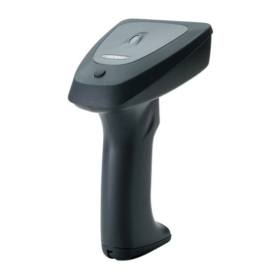
- Page 1 Bar Code Handy Scanner GT10B-SB GT10B-LB User's Manual...
- Page 2 If it is judged by DENSO WAVE INCORPORATED that malfunction of the product is due to the product having been dropped or subjected to impact, repairs will be made at a reasonable charge even within the warranty period.
- Page 3 FCC and RSS-210 Regulations This device complies with Part 15 of the FCC Rules. Operation is subject to the following two conditions: This device complies with Part 15 of the FCC Rules and RSS-210 Rules Operation is subject to the following two conditions: (1) this device may not cause harmful interference, and (2) this device must accept any interference received, including interference that may cause undesired operation.
- Page 4 The radio frequency module that complies with the Directive 99/5/EC (R&TTE) is mounted on this device (GT10B-SB/LB). DECLARATION OF CONFORMITY Directive 99/5/EC (R&TTE) Manufacturer or Authorized representative : - Name : DENSO WAVE INCORPORATED - Address : 1-1, Showa-cho, Kariya-shi, Aichi-ken, 448-8661, Japan Description product : - Product name : Bluetooth Board...
-
Page 5: Table Of Contents
Contents Preface ..................................... SAFETY PRECAUTIONS.............................. ii Components Required ..............................viii ® Bluetooth Wireless Communication Link ........................ix Care and Maintenance ..............................x Chapter 1 Part Names and Functions ........................... 1 ® Chapter 2 Bluetooth Interface ............................ 2 ® Enabling Bluetooth Interface ........................ - Page 6 8.6.2 Rules for data editing........................29 8.6.3 AI table ............................30 Chapter 9 Beeper, Indicator LED and Vibrator ......................35 Beeper................................. 35 Indicator LED............................. 37 Vibrator ..............................38 Chapter 10 Communication............................39 ® 10.1 Bluetooth Interface........................... 39 10.2 Communication Format..........................40 10.2.1 Data transmission format.......................
- Page 7 Data verification mode ........................86 Notification of a scanning failure under software control..............88 Reading with scanner mounted on charger..................89 ® Chapter 14 Bar-Coded Parameter Menu for Bluetooth Adapters (BA10-RKU)............90 ® 14.1 Configuring the Bluetooth Adapter from the Scanner................90 ®...
-
Page 8: Preface
Preface This user's manual sets forth the procedures for handling, connecting, operating, and cleaning your bar code handy scanner. Before you do anything else, study it carefully to make sure that you use the product both correctly and effectively. Also keep it handy for ready reference. -
Page 9: Safety Precautions
SAFETY PRECAUTIONS Be sure to observe all these safety precautions. Please READ through these instructions carefully. They will enable you to use the scanner correctly. Always keep this manual nearby for speedy reference. Strict observance of these warnings and cautions is a MUST for preventing accidents that could result in bodily injury and substantial property damage. - Page 10 To System Designers: • When introducing the scanner in those systems that could affect human lives (e.g., medicines management system), develop applications carefully through redundancy and safety design which avoids the feasibility of affecting human lives even if a data error occurs. Handling the battery cartridge Wrong handling of the battery cartridge could result in a heat, smoke, explosion, or fire.
- Page 11 Handling the scanner Wrong handling of the scanner could result in a scanner failure, heat, or smoke. Be sure to observe the following. • If using the hand strap or neck strap, exercise due care to avoid getting them caught in other objects or entangled in rotating machinery.
- Page 12 Handling the AC adapter Wrong handling of the AC adapter could result in a failure, heat, or smoke. Be sure to observe the following. • Do not scratch, modify, bend, twist, pull, or heat the AC adapter cable. Do not place heavy material on the cable or allow the cable to get pressed under heavy material.
- Page 13 Handling the scanner and AC adapter Wrong handling of the scanner or AC adapter could result in a failure, heat, or smoke. Be sure to observe the following. • Never disassemble or modify the scanner or AC adapter; doing so could result in an accident such as break or fire.
- Page 14 • If you are not using the scanner for a long time, be sure to remove the battery cartridge for safety. Failure to do so could result in a fire. • When unplugging the AC adapter from the electrical outlet, hold the connector housing not the cable.
-
Page 15: Components Required
Components Required ® The scanner GT10B-SB/LB requires the following components that differ depending upon whether the Bluetooth adapter is used and which interface is selected. ® When using the Bluetooth adapter (BA10-RKU) Basic components ® The table below lists the basic components required for the use of the Bluetooth adapter. -
Page 16: Bluetooth ® Wireless Communication Link
® Bluetooth Wireless Communication Link ® The scanner GT10B-SB/LB uses Bluetooth wireless networking technology. Item Specifications ® Standard Bluetooth Specification Ver. 1.1 Radio output Class 2 (maximum 2.5 mW) Profile(s) supported Serial port profile Communications range (reference value* Max. 10 m, with no obstructions ®... -
Page 17: Care And Maintenance
Care and Maintenance Dust and other foreign matter on the clear plate of the reading window can impede bar code input, so regularly check for it and remove it as the usage environment warrants. • To clean the plate, first blow the dust away with an airbrush. Then gently wipe the plate with a cotton swab or the similar soft one. -
Page 18: Chapter 1 Part Names And Functions
Chapter 1 Part Names and Functions Indicator LED This turns blue after a successful read and red if there is an error. It also indicates the ® Bluetooth interface status and, when the scanner is in its charger, the charging status. Reading window (Refer to Chapter 9 for details.) Point this at the bar... -
Page 19: Chapter 2 Bluetooth ® Interface
® Chapter 2 Bluetooth Interface ® ® For terms relating to Bluetooth wireless communication in this manual, refer to Appendix 3 "Bluetooth Glossary." ® Enabling Bluetooth Interface Using the scanner for the first time or any other time that the "End operation" is selected requires scanning the ®... -
Page 20: Establishing Bluetooth ® Wireless Link
2.5.0.) * Registered users can download the configuration software (ScannerSetting) from QBdirect, their customer support section on the Denso Wave website at no extra charge. For further details on QBdirect or to register, visit the following URL. - Page 21 3) Select an arbitrary version and press the OK button. ® 4) On the Bluetooth window shown below, select "Connect to optional Bluetooth device" as the Connection ® method, "Master" as the Mode, "Address" as the Access point. In the text box, enter the Bluetooth address obtained in step (1) above.
- Page 22 When using a commercially available bar code generator, generate it in the following format. Bar code type Code 128, Code set A ® Value ADDR followed by Bluetooth address (in hexadecimal) ® (Example) Bluetooth address 000AF1234567 ADDR000AF1234567 ® (3) Use the scanner to read the "Bluetooth address"...
-
Page 23: Breaking Bluetooth ® Wireless Links
® Breaking Bluetooth Wireless Links ® Holding down the magic key in the regular read mode breaks the scanner's Bluetooth wireless link. ® Scanning the following bar code forcibly breaks the scanner's Bluetooth wireless link. ® Break Bluetooth wireless link ®... -
Page 24: Indication Of Bluetooth ® Wireless Link Status
® Indication of Bluetooth Wireless Link Status ® The scanner's indicator LED and beeper together indicate the status of the scanner's Bluetooth wireless link. When the trigger switch is held down: Indicator LED Beeper Scanner Status ® Red, blinking Reading is not possible when there is no Bluetooth wireless link. -
Page 25: Chapter 3 Reading Bar Codes
The effective scan range depends on the model and the distance from the scanner to the target. GT10B-SB: approximately 10 cm (3.94") for a scan distance of 7 cm (2.76") GT10B-LB: approximately 17 cm (6.69") for a scan distance of 18 cm (7.09") Note: Having more than one bar code within the field of view either causes the read to fail or produces multiple input. - Page 26 Reading RSS-14 Stacked and RSS-14 Stacked Omnidirectional symbols The scanner reads RSS-14 Stacked and RSS-14 Stacked Omnidirectional symbols in two steps. In the 1st step, it scans either one of the 1st and 2nd rows of the target symbol and accumulates the data in itself. In the 2nd step, it scans the remaining row, edits the 1st and 2nd row data read, and then sends the data to the host.
- Page 27 Switching to sleep mode for power saving After completion of scanning, the scanner switches from standby to sleep mode to save power. The scanner in sleep mode takes more time to start and complete a sequence of scanning operation than the one on standby. Select the transition period from standby to sleep mode to meet your scanning intervals, using the configuration software (ScannerSetting).
-
Page 28: Chapter 4 Customizing The Scanner
(This software also offers batch-process bar code printouts for read by scanners in the field.) * Registered users can download the configuration software (ScannerSetting) from QBdirect, their customer support section on the Denso Wave website at no extra charge. For further details on QBdirect or to register, visit the following URL. -
Page 29: Chapter 5 Scanning Control
Chapter 5 Scanning Control Two types of scanning controls are available—Trigger switch control and Software control. Trigger switch control: Pressing the trigger switch readies the scanner for scanning. Software control: Instead of pressing the trigger switch, you send control commands from the host computer via the USB-COM interface to ready the scanner for scanning or put the scanner on standby. -
Page 30: Software Control
Software Control You can control the scanner by sending scanning control commands from the host computer, instead of pressing the trigger switch. Scanning control commands include R, READON, LON, RC, Z, READOFF and LOFF and they are restricted by the trigger switch operating mode, as listed below. - Page 31 Failure read • Auto-off mode 1 Ready-to-scan command Command input (RxD) Bar code 1 to 5 sec. Illumination LED Failure notification Data output (TxD) • Momentary switching mode 1 Ready-to-scan command Command input (RxD) Standby command Bar code Illumination LED Failure notification Data output (TxD) (2) Continuous reading mode...
-
Page 32: Auto Sensing Mode-Automatic Detection Of Labels
Note: Given below is a guide for scanning EAN-13 symbols in auto sensing mode under these conditions: At the center of the effective scan range and at the ambient illuminance of 500 lux or higher. GT10B-SB: Scan distance of approx. 21 cm (8.27") GT10B-LB: Scan distance of approx. 40 cm (15.75") Note: It is sometimes necessary to vary the scanning angle or distance to eliminate reflections of the illumination and ambient light off highly reflective labels. -
Page 33: Reading With Scanner Mounted On Charger
Reading with Scanner Mounted on Charger A setting enables read operation with the scanner mounted on the charger, drawing its power from the charging pins, so reading can continue regardless of the battery cartridge's charge level. The following table shows how the trigger switch operating mode affects charging while this function is in use. Momentary switch mode 1, for example, allows charging during standby intervals between reads. -
Page 34: Chapter 6 Magic Key Control
Chapter 6 Magic Key Control ® Holding down the magic key breaks Bluetooth wireless links. Note that, in the data verification mode, it cannot break those links since the magic key is used to register master data. The magic key can also act as an auxiliary key for scanning or data transfer. You can assign any of the following five functions or no function at all to the magic key. - Page 35 The following table lists the relationship between the magic key functions and trigger switch operating modes. (It applies to both the regular read mode and data verification mode.) The "--" indicates that the scanner ignores the magic key functions assigned. In auto-off mode 1, for example, the ready/standby switching function is ignored. Trigger switch operating modes Auto sensing Momentary...
-
Page 36: Chapter 7 Scanning Functions
Chapter 7 Scanning Functions Data Verification Mode The data verification mode verifies the bar code data read against the master data stored in the scanner and reports the match status with data output. Data verification read is available in two types--"n-point verification" and "2-point verification." Selecting the n-point verification requires registering master data only one time for 1:n verification. - Page 37 2-point verification read After registration of master data, the scanner reads a bar code, verifies the bar code data read against the master data and then becomes ready to register new master data. - Switch to the data verification mode. Use the bar-coded parameter menu or configuration software.
-
Page 38: Verification Conditions
7.1.2 Verification conditions You can specify a verification starting position and the number of characters to check. • Starting position: The choices are 1st through 7th characters. • Number of characters: The choices are 1 through 7 and everything following the starting position (up to a maximum of 32 characters). -
Page 39: Verification Result Output
7.1.3 Verification result output (1) Report of match/mismatch status You can select any of the following report types by using the bar-coded parameter menu or configuration software (ScannerSetting). Selecting "Disable transmission" reports nothing. Setting If there is a match: If there is a mismatch: Disable transmission. -
Page 40: Output Of The Master Data Registered
7.1.4 Output of the master data registered Scanning the "Output master data" bar code given below lets the scanner output the master data registered in the verification setup procedure. Note: In the 2-point verification read, the scanner cannot read this bar code, so it cannot output master data. Output master data ®... -
Page 41: Specifying The Numbers Of Digits Of Standard 2Of5 And Interleaved 2Of5 Symbols To Read, By Scanning Bar Codes
Specifying the Numbers of Digits of Standard 2of5 and Interleaved 2of5 Symbols to Read, by Scanning Bar Codes You can specify the numbers of digits of Standard 2of5 and Interleaved 2of5 symbols to read. First enable the parameter "specification of the number of digits by bar code scanning" by using the bar-coded parameter menu or configuration software. -
Page 42: Chapter 8 Data Editing
Chapter 8 Data Editing The scanner can edit bar code data read in the format specified with the configuration software (ScannerSetting) and transfer it to the host computer. The format specification parameters retain their settings until the configuration software (ScannerSetting) or bar-coded parameter menu sets "All defaults."... -
Page 43: Substituting Data
(3) Extracting data from the specified start to tail positions The start position must be within the range from the 2nd to 99th digits. If the number of digits in bar code data read does not reach the specified start position, an error occurs. (Example) Start position Output data... -
Page 44: Blocksorting Data
(2) Transferring the substituted element string If the bar code data contains the specified substitution string within the specified search area, the scanner transfers the substituted element string followed by the bar code data read. (Example) Search start position Search string Substitution string Output data 2nd digit... -
Page 45: Parenthesizing Ais (Application Identifier) In Ean-128 Data
Parenthesizing AIs (Application Identifier) in EAN-128 Data The scanner parenthesizes all AIs contained in EAN-128 data read and transfers the data. (For the definition of AIs, see Section 8.6.3.) The following sample bar code and scanner settings output data with AIs parenthesized as listed below. - Bar code sample Bar code type: EAN-128, Data read: 0194901234567894110308081303081017040208 - Scanner settings... -
Page 46: Data Editing Notes
(3) Tab (ASCII 09h <HT>) Specifying a tab as a delimiter outputs tab-delimited data. No tab follows the tail of the data. A header and terminator are added to the full string. A prefix, suffix, the number of digits, and code ID mark can be also added to the full string if their transmissions are enabled. -
Page 47: Ai Table
(12) Conversions apply to Codabar start/stop characters and include them in the number of digits. (13) Conversions force Codabar start/stop characters, if included in the output, to lower case. (14) Conversions skip Code 39 start/stop characters and do not include them in the number of digits. (15) The output never contains Code 39 start/stop characters regardless of their settings. - Page 48 Format Description n3+n..19 Batch or Lot Number (Transitional Use) (**) n3+an..30 Additional Product Identification Assigned by the Manufacturer n3+an..30 Customer Part Number n3+an..30 Secondary Serial Number n3+an…30 Reference to Source Entity n3+n27 Global Serial Number n3+n13+n..17 Global Document Type Identifier n2+n..8 Quantity 310n...
- Page 49 Format Description 345n n4+n6 Width, Diameter, or 2nd Dimension, Feet, Logistics (***) 346n n4+n6 Width, Diameter, or 2nd Dimension, Yards, Logistics (***) 347n n4+n6 Depth, Thickness, Height, or 3rd Dimension, Inches, Logistics (***) 348n n4+n6 Depth, Thickness, Height, or 3rd Dimension, Feet, Logistics (***) 349n n4+n6 Depth, Thickness, Height, or 3rd Dimension, Yards, Logistics (***)
- Page 50 Format Description Identification of a Physical Location--EAN.UCC Global Location n3+n13 Number n3+n13 EAN.UCC Global Location Number of the Invoicing Party n3+an..20 Ship to (Deliver to) Postal Code Within a Single Postal Authority Ship to (Deliver to) Postal Code with Three-Digit ISO Country Code n3+n3+n..9 Prefix n3+n3...
- Page 51 Format Description n2+an..30 Company Internal Information--Company n2+an..30 Company Internal Information--Carrier n2+an..30 Company Internal Information--Carrier n2+an..30 Company Internal Information--Company n2+an..30 Company Internal Information--Company n2+an..30 Company Internal Information To indicate only year and month, DD must be FILLED with "00." (**) n indicates the length of data. (***) n indicates the decimal point position.
-
Page 52: Chapter 9 Beeper, Indicator Led And Vibrator
Chapter 9 Beeper, Indicator LED and Vibrator Beeper (1) Beeping The scanner emits a short, long, one-shot, or intermittent beep to indicate the scanner status as described below. The intermittent and one-shot beeps apply when the scanner reads an RSS-14 Stacked or RSS-14 Stacked Omnidirectional symbol. - Page 53 One-shot beep* (40 ms) or intermittent beep* (at 60 ms intervals) when: • either one of the 1st and 2nd rows of an RSS-14 Stacked or RSS-14 Stacked Omnidirectional symbol is read. (Selecting an intermittent beep continues to beep as long as either one of the 1st and 2nd rows is left unread.) (Upon completion of a read, the beeper emits a short beep* The configuration software (ScannerSetting) provides three choices for the beeping time of a short beep--60, 80, and 120 ms.
-
Page 54: Indicator Led
Indicator LED The indicator LED lights or flashes in blue, green, red or orange to indicate the scanner status as described below. Lights in blue when: • a read of a bar code is successfully complete (Note that when the auto sensing mode switching function* is enabled, the indicator LED lights in green.), •... -
Page 55: Vibrator
The indicator LED can be disabled with the bar-coded parameter menu or configuration software (ScannerSetting). In any of the following cases, however, the indicator LED comes on regardless of the current LED setting: - When the scanner is being customized with the bar-coded parameter menus (Chapters 13 and 14). - When the configuration software (ScannerSetting) starts up or accepts any new setting. -
Page 56: Chapter 10 Communication
Chapter 10 Communication ® 10.1 Bluetooth Interface The bar-coded parameter menu and the configuration software (ScannerSetting) provide a choice of various communications conditions. Under the communications conditions you choose, bar code data read can be transferred to the external equipment or computer. (1) Communications protocol You can select either "Non-acknowledge mode,"... -
Page 57: Communication Format
10.2 Communication Format 10.2.1 Data transmission format Select one of the following two data transmission formats. No. of digits Code ID Header Prefix Bar code data Suffix Terminator mark No. of digits Code ID Header Prefix Bar code data Suffix Terminator mark (1) Header/Terminator... - Page 58 You can also select whether or not to transmit the code ID mark. (Default: No transmission) Code ID mark Bar code symbologies Type 1 Type 2 Type 5 Type 6 Type 3 Type 4 (DENSO 1) (DENSO 2) (AIM)* (AIM Type 2)* UPC-A UPC-E EAN-13 EAN-8 UPC-A with 2-digit add-on...
- Page 59 (4) Number of digits This optional field specifies the number of digits (2 or 4 digits) of bar code data to transmit or disables the transmission (default). Note that UPC and EAN codes (except EAN-128) skip this field. n1 : thousands (0 to 9) n2 : hundreds (0 to 9) n3 : tens (0 to 9) n4 : units (0 to 9)
- Page 60 Codabar (NW-7) Start code Data Stop code The Codabar symbology may or may not contain a check digit. You can select whether or not to check a check digit and transmit the check digit read. There are two check digit methods available: modulo arithmetic-16 (MOD-16) and 7-check method.
-
Page 61: Gtin Format Conversion
10.2.2 GTIN Format Conversion If the GTIN format conversion function is enabled, EAN-13, EAN-8, UPC-A, UPC-E and Interleaved 2of5 (14-digit) codes can be output in GTIN format, and GTIN format RSS and EAN-128 codes can be output by EAN/JAN (product code format). -
Page 62: Data Packaging (Packetizing)
10.3 Data Packaging (Packetizing) ® Data packaging is available to boost the reliability of data transfers over the Bluetooth wireless link from the scanner ® ® to the Bluetooth adapter (BA10-RKU), commercially available Bluetooth device, or other target device. Data packaging wraps the bar code data in packets with the following format. After sending a packet, the scanner waits for a response from the target device. - Page 63 ® Using scanner connected to Bluetooth adapter Scanner settings: Data packaging mode (to BA10-RKU) ® Bluetooth adapter settings: GT10 series as target Transfer data packets. Return ACK and transfer the data packets to the host. Send ACK for a successful transfer; NAK for an unsuccessful one.
- Page 64 Example of analysis for packet received Data received (hexadecimal) 10H 02h 00h 13h 00h 00h 31h 32h 33h 34h 35h 36h 37h 38h 0Dh C4h 18h 10h 03h Header Number of Spare Transfer data Terminator data bytes (1) Compare data lengths. Data length received in packet: 0013h = 19 bytes Data received in packet: 19 bytes (2) Compare CRCs.
-
Page 65: Chapter 11 Charging And Replacing The Battery Cartridge
Chapter 11 Charging and Replacing the Battery Cartridge 11.1 Charging and Discharging the Battery Cartridge When the battery cartridge charge drops to a level requiring recharging, a warning sounds and the indicator LED starts flashing orange once every five seconds. This flashing continues until the scanner is recharged. Recharge the scanner as promptly as possible. - Page 66 Charging procedure (1) Connect the AC adapter to the charger and then plug it into an electrical outlet. Confirm that the green power supply LED lights. (2) Place the scanner in the charger. The charger's orange charge LED lights and the scanner's indicator LED turns red, indicating the start of charging. When charging is complete, approximately 2.5 hours later, (if the battery cartridge has been fully discharged), the charger's orange charge LED goes off and the scanner's indicator LED turns green.
-
Page 67: Replacing The Battery Cartridge
11.2 Replacing the Battery Cartridge The rechargeable battery cartridge is a consumable part with a finite service life. It is time to replace it when a full charge lasts a significantly shorter time than previously. Note that the service life varies with usage conditions Follow the replacement procedure given below also when it is necessary to take the battery cartridge out of the scanner due to any scanner trouble. - Page 68 (5) Connect a new battery cartridge to the battery cable connector. Note: Do not peel off the protection film covering a battery cartridge. (6) Insert the new battery cartridge into the scanner so that the battery pull strap is routed below the battery cartridge as shown below.
-
Page 69: Recycling The Battery Cartridge
11.3 Recycling the Battery Cartridge Battery Cartridge Recycling Request This product uses a Nickel-metal hydride battery that contains scarce, recyclable resources. We kindly ask for your cooperation in recycling to ensure reuse of these resources. The crossed-out wheeled bin is applicable for EU member status only. -
Page 70: Chapter 12 Parameters And Defaults
Chapter 12 Parameters and Defaults The tables below list the parameters and their defaults. Those parameter settings can be changed with the bar-coded parameter menu and configuration software (ScannerSetting), except shadowed ones only with the configuration software. When the scanner leaves the factory, all of these parameters are set to defaults. ®... -
Page 71: Data Transmission Format And Bar Code Symbologies
Transmission of code ID mark √ Disable Before prefix Code ID mark position √ After prefix √ Type 1 (DENSO 1) Section 10.2.1 (3) Type 2 (DENSO 2) Type 3 Code ID mark Type 4 Type 5 (AIM) Type 6 (AIM Type 2) - Page 72 UPC-A/E, EAN-13/8 Items Parameters Defaults Refer to: √ Enable Scanning UPC-A, UPC-E, EAN-13 and EAN-8 Disable Enable Scanning UPC/EAN with 2-digit add-on √ Disable Enable Scanning UPC/EAN with 5-digit add-on √ Disable √ Enable Transmission of the number system character of UPC-A Disable √...
- Page 73 Standard 2of5 Items Parameters Defaults Refer to: Enable, without C/D Scanning Standard 2of5 Enable, with C/D √ Disable Minimum number of digits readable 3 digits for Standard 2of5 1 to 99 digits (See Note 2.) Maximum number of digits readable 99 digits for Standard 2of5 √...
- Page 74 Item Parameters Defaults Refer to: √ MOD-16 Check digit method for Codabar (NW-7) 7-check method Section 10.2.1 (5) Transmit a/b/c/d Transmission of start/stop codes Transmit A/B/C/D for Codabar (NW-7) √ Disable Code 32 Item Parameters Defaults Refer to: Enable Conversion from Code 39 to Code 32 format √...
- Page 75 Code 128, EAN-128 Items Parameters Defaults Refer to: √ Enable Scanning Code 128 Disable √ Enable Scanning EAN-128 Disable Minimum number of digits readable 1 digit for Code 128 and EAN-128 1 to 99 digits (See Note 2.) (excluding 1-digit C/D) Maximum number of digits readable 99 digits for Code 128 and EAN-128...
-
Page 76: Trigger Switch Control And Magic Key Control
(3) Trigger switch control and magic key control Items Parameters Defaults Refer to: Auto-off mode 1 Auto-off mode 2 √ Momentary switching mode 1 Trigger switch control Section 5.1 Momentary switching mode 2 Continuous reading mode Auto sensing mode 1 sec. 2 sec. -
Page 77: Beeper, Indicator Led And Vibrator
(4) Beeper, indicator LED and vibrator Items Parameters Defaults Refer to: √ Enable Beeper Section 9.1 Disable √ Short (60 ms) Beeping time of a short beep Section 9.1 Medium (80 ms) Long (120 ms) √ High Beeper volume Medium Section 9.1 Low (2.0 kHz) √... -
Page 78: Data Verification Mode
(5) Data verification mode Items Parameters Defaults Refer to: √ Regular read mode Scanning modes Data verification mode 2-point verification Data verification type √ n-point verification √ Disable Verification retry after mismatch in 2-point verification Enable Disable transmission/ √ Disable transmission Enable bar code data transmission/ Verification result output in data Disable transmission... -
Page 79: Speed-/Depth-Priority Scanning
Speed-priority scanning Chapter 3 Speed-/depth-priority scanning (See Note 4.) √ Depth-priority scanning (Note 4) The default is speed-priority scanning for the GT10B-SB, and depth-priority scanning for the GT10B-LB. (8) Switching to sleep mode for power saving Items Parameters Defaults Refer to: √... -
Page 80: For Bluetooth ® Adapter: Bluetooth ® Communications Parameters
® ® (9) For Bluetooth adapter: Bluetooth communications parameters Items Parameters Defaults Refer to: Enable Clear the transfer buffer when the ® Bluetooth link is broken √ Disable √ GT10 series Connection target Others √ Enable Reception of split packets Disable ®... - Page 81 Items Parameters Defaults Refer to: √ Inboard numeric keys Numeric key type (See Note 6.) Numeric keypad Enable Special key transmission (See Note 7.) √ Disable selecting (Note 6) When "Numeric keypad," set the host's Num Lock to ON. Inboard numeric keys Numeric keypad U.S.
-
Page 82: For Bluetooth ® Adapter: Usb-Com Interface Communications Parameters
® (12) For Bluetooth adapter: USB-COM interface communications parameters The following settings take effect only when the USB-COM interface is set up. Items Parameters Defaults Refer to: √ Enable CTS signal monitor Disable ® (13) For Bluetooth adapter: RS-232C interface communications parameters The following settings take effect when the RS-232C interface is set up. -
Page 83: For Bluetooth ® Adapter: Ps/2 Keyboard Interface Communications Parameters
® (14) For Bluetooth adapter: PS/2 keyboard interface communications parameters The following settings take effect when the PS/2 keyboard interface is set up. Items Parameters Defaults Refer to: √ With external keyboard Keyboard connection type Without external keyboard ON (Uppercase letter) Caps Lock of host's keyboard √... - Page 84 Items Parameters Defaults Refer to: Enable Special key transmission (See Note 7.) √ Disable (Note 7) Special key transmission applies to the fields except header and terminator in the data transmission format. Enabling this function substitutes E7h to FDh data with the special keys as listed below and transmits the substituted data to the host.
-
Page 85: For Bluetooth ® Adapter: Substitution Of Header/Terminator For Ps/2 And Usb Keyboard Interfaces
® (15) For Bluetooth adapter: Substitution of header/terminator for PS/2 and USB keyboard interfaces The following settings take effect only when the PS/2 or USB keyboard interface is set up. Items Parameters Defaults Refer to: Enable Substitution of header √ Disable Single ASCII character Search string for header... -
Page 86: Chapter 13 Bar-Coded Parameter Menu For Scanners
Chapter 13 Bar-Coded Parameter Menu for Scanners 13.1 Parameter Setting Procedure Using the Bar-Coded Parameter Menu Scan the "Start operation" bar code if the "End operation" has been selected. Start operation ↓ Three beeps Scan the "Start setting" bar code. ®... -
Page 87: Bar-Coded Parameter Menu For Scanners
13.2 Bar-Coded Parameter Menu for Scanners To set parameters given on this page, it is necessary to first scan the "Start operation" bar code, but not necessary to scan the "Start setting" or "End setting" bar code given on the next page. ®... -
Page 88: Starting/Ending The Setting Procedure And Reverting To Defaults
Starting/ending the setting procedure and reverting to defaults To set parameters given on the following pages, it is necessary to scan the "Start setting" bar code. To complete the setting procedure, scan the "End setting" bar code. Start setting End setting All defaults... -
Page 89: Bluetooth ® Interface Communications Parameters
® Bluetooth interface communications parameters Communications protocol Non-acknowledge mode (default) ACK/NAK mode Data packaging mode (to host) Data packaging mode (to BA10-RKU) Header None (default) Terminator CR (default) CR LF None... - Page 90 Timeout period for slave to wait for a connection request 2 minutes (default) 4 minutes 10 minutes 30 minutes ® Clearing the transfer buffer when the Bluetooth wireless link breaks Enable Disable (default)
-
Page 91: Data Transmission Format And Bar Code Symbologies
Enable Disable (default) Code ID mark position Before prefix After prefix (default) Types of code ID mark Type 1 (DENSO 1) (default) Type 2 (DENSO 2) Type 3 Type 4 Type 5 (AIM) Type 6 (AIM Type 2) Transmission of the number of digits (not applicable to UPC/EAN codes) - Page 92 UPC-A/-E and EAN-13/-8 Scanning UPC-A, UPC-E, EAN-13 and EAN-8 Enable (default) Disable Scanning UPC/EAN with Add-on Enable, no restriction on add-on digits Enable 5-digit add-on only Enable 2-digit add-on only Disable (default) Transmission of the number system character of UPC-A Enable (default) Disable Transmission of the number system character of UPC-E...
- Page 93 Transmission of padding characters "0" for the specified number of digits of UPC-E Enable Disable (default) Transmission of a check digit for UPC-A Enable (default) Disable Transmission of a check digit for UPC-E Enable (default) Disable Transmission of a check digit for EAN-13 Enable (default) Disable Transmission of a check digit for EAN-8...
- Page 94 Transmission format of EAN-8 (Conversion to EAN-13) Enable conversion Disable conversion (default) Transmission format of UPC-E (Conversion to UPC-A) Enable conversion Disable conversion (default) Transmission of country code for EAN-13 Enable (default) Disable Conversion to ISBN/ISSN format for EAN-13 Enable Disable (default) Standard 2of5 Scanning Standard 2of5...
- Page 95 Transmission of a check digit for Standard 2of5 Enable (default) Disable Specification of the number of digits for Standard 2of5, by bar code scanning Enable Disable (default) Interleaved 2of5 Scanning Interleaved 2of5 Enable, without C/D (default) Enable, with C/D Disable Transmission of a check digit for Interleaved 2of5 Enable (default) Disable...
- Page 96 Codabar (NW-7) Scanning Codabar (NW-7) Enable, without C/D (default) Enable, with C/D Disable Transmission of a check digit for Codabar (NW-7) Enable (default) Disable Check digit method for Codabar (NW-7) MOD-16 (default) 7-check method Transmission of start/stop codes for Codabar (NW-7) Transmit a/b/c/d Transmit A/B/C/D Disable (default)
- Page 97 Code 32 Conversion from Code 39 to Code 32 format Enable Disable (default) Transmission of leading "A" in Code 32 data Enable Disable (default) Checking of a check digit in Code 32 data Enable Disable (default)
- Page 98 Code 39 Scanning Code 39 Enable, without C/D (default) Enable, with C/D Disable Transmission of a check digit for Code 39 Enable (default) Disable Transmission of start/stop codes for Code 39 Enable Disable (default) Conversion to Full ASCII for Code 39 Enable Disable (default) Code 93...
- Page 99 Code 128/EAN-128 Scanning Code 128 Enable (default) Disable Scanning EAN-128 Enable (default) Disable Transmission of FNC1 for Code 128 and EAN-128 Transmit after conversion to GS (default) Disable Scanning MSI Enable Disable (default) Plessey Scanning Plessey Enable Disable (default)
- Page 100 Scanning RSS-14, RSS-14 Truncated, RSS-14 Stacked, RSS-14 Stacked Omnidirectional Enable Disable (default) Scanning RSS Limited Enable Disable (default) GTIN GTIN format conversion Enable Disable (default) Conversion type from EAN/UPC/Interleaved 2of5 (14-digit) to GTIN format 16-digit GTIN format (default) 14-digit GTIN format Disable conversion Conversion type from RSS/EAN-128 in GTIN format to EAN format 14-digit EAN format (default)
-
Page 101: Trigger Switch Control And Magic Key Control
Trigger switch control and magic key control Trigger switch control Auto-off mode 1 Auto-off mode 2 Momentary switching mode 1 (default) Momentary switching mode 2 Continuous reading mode Auto sensing mode Magic key control Illumination switching function Data retransfer function Specific character transfer function Ready/standby switching function Auto sensing mode switching function... -
Page 102: Beeper, Indicator Led And Vibrator
Scanner sensibility level in auto sensing mode High Medium (default) Beeper, indicator LED and vibrator Beeper Enable (default) Disable Trigger timing for the reading completion beeper and indicator LED Before data transmission (default) After data transmission Beeper when reading RSS-14 Stacked and RSS-14 Stacked Omnidirectional Enable (default) Disable Beeping pattern when reading RSS-14 Stacked and RSS-14 Stacked Omnidirectional... -
Page 103: Data Verification Mode
Indicator LED Enable (default) Disable Vibrator OK vibrations (default) NG vibrations Disable Data verification mode Data verification mode Regular read mode (default) Data verification mode Data verification type 2-point verification n-point verification (default) Verification retry after mismatch in 2-point verification Disable (default) Enable... - Page 104 Verification result output in data verification mode (Report of match/mismatch status) Disable transmission/Disable transmission (default) Enable bar code data transmission/Disable transmission Enable bar code data transmission/Enable NG transmission Enable OK transmission/Enable NG transmission Verification start position in data verification mode 1st character (default) 2nd character 3rd character...
-
Page 105: Notification Of A Scanning Failure Under Software Control
Number of characters to verify, starting from the verification start position 1 character 2 characters 3 characters 4 characters 5 characters 6 characters 7 characters Not specified (default) Scan lock in data verification read Enable Disable (default) Notification of a scanning failure under software control Enable CAN (18h) transmission (default) Enable "ERROR"... -
Page 106: Reading With Scanner Mounted On Charger
Reading with scanner mounted on charger Enable Disable (default) -
Page 107: Chapter 14 Bar-Coded Parameter Menu For Bluetooth ® Adapters (Ba10-Rku)
® Chapter 14 Bar-Coded Parameter Menu for Bluetooth Adapters (BA10-RKU) ® 14.1 Configuring the Bluetooth Adapter from the Scanner ® The scanner can configure the Bluetooth adapter by transferring the adapter parameter settings held in the scanner ® memory via the Bluetooth wireless link using the following procedure. - Page 108 After normal end of transfer of parameter settings, the scanner's indicator LED turns blue with one beep. If the parameter transfer does not end normally, the scanner's indicator LED turns red End of transfer with three beeps. ® Both the scanner and Bluetooth adapter automatically reset themselves regardless of whether the parameter transfer ends normally.
-
Page 109: Bar-Coded Parameter Menu For Bluetooth ® Adapters
® 14.2 Bar-Coded Parameter Menu for Bluetooth Adapters Starting and ending the setting procedure, and restoring to defaults Start setting End setting All defaults Setting the interface USB keyboard interface (default) USB-COM interface RS-232C interface PS/2 keyboard interface... -
Page 110: Bluetooth ® Interface Communications Parameters
® Bluetooth interface communications parameters ® Clearing the transfer buffer when the Bluetooth wireless link breaks Enable Disable (default) Connection target GT10 series (default) Others Reception of split packets Enable (default) Disable... -
Page 111: Usb Keyboard Interface Communications Parameters
USB keyboard interface communications parameters Caps mode (USB keyboard interface) Auto setting (default) Manual setting Caps Lock of host's keyboard (USB keyboard interface) OFF (default) Keyboard type (USB keyboard interface) Select the connected keyboard type. U.S. English (101 keyboard) (default) Germany (102 keyboard) French (102 keyboard) U.K. - Page 112 Data transmission interval (USB keyboard interface) ® This parameter provides a choice of the following data transmission intervals that apply when the Bluetooth adapter transfers data read by the scanner to the host computer. 3 ms (default) 6 ms 10 ms 16 ms 30 ms 50 ms...
-
Page 113: Usb-Com Interface Communications Parameters
USB-COM interface communications parameters Monitoring CTS (USB-COM interface) Enable (default) Disable... -
Page 114: Rs-232C Interface Communications Parameters
RS-232C interface communications parameters Transmission speed (RS-232C interface) 1200 bps 2400 bps 4800 bps 9600 bps (default) 14400 bps 19200 bps 38400 bps 57600 bps 115200 bps Data bit (RS-232C interface) 7 bits 8 bits (default) Parity (RS-232C interface) EVEN None (default) - Page 115 Stop bit (RS-232C interface) 1 bit (default) 2 bits Monitoring CTS (RS-232C interface) Enable (default) Disable...
-
Page 116: Ps/2 Keyboard Interface Communications Parameters
PS/2 keyboard interface communications parameters Keyboard connection type (PS/2 keyboard interface) With external keyboard (default) Without external keyboard Caps Lock of host's keyboard (PS/2 keyboard interface) Select the Caps Lock state that matches the host's keyboard state. OFF (default) Num Lock mode (PS/2 keyboard interface) Select the Num Lock state that matches the host's keyboard state. - Page 117 Data transmission interval (PS/2 keyboard interface) Select the data transmission interval that matches the computer's processing speed. Setting a too short interval may cause the computer to fail to display bar code data correctly (e.g., character missing). If it happens, set a longer interval. 1 ms (default) 5 ms 10 ms...
-
Page 118: Chapter 15 Troubleshooting
Chapter 15 Troubleshooting Problem 1: Bar code data not displayed on the computer screen correctly. Probable cause What to do: • The target Bluetooth ® • Refer to the user's manual of the target Bluetooth ® device is not ready for communication. - Page 119 Problem 4: Scanner's operation period too short even after recharge. Probable cause What to do: • If fully discharging and then recharging (i.e. • Replace the battery cartridge. refreshing) cannot solve this problem, the service (See Section 11.2.) life is expired. (See Section 11.1.) •...
-
Page 120: Appendix 1 Specifications
RSS-14 Stacked Omnidirectional, RSS Limited (The RSS Expanded and RSS Expanded Stacked symbologies are not supported by this scanner.) Scanning direction Bidirectional Scanning resolution GT10B-SB: 4.9 mils (0.125 mm) GT10B-LB: 7.5 mils (0.19 mm) ±40° (∗ Elevation angle (skew) ±20° (∗ Tilt angle (pitch) - Page 121 Reading diagrams GT10B-SB Speed-priority scanning Unit: inches (mm) Scan range (incl. right and left margins) 0.53" (13.5) 0.53" (13.5) 1.97" (50) 4.9 mils (0.125) 3.94" (100) 7.5 mils (0.19) 9.8 mils (0.25) 5.91" (150) Module size 13.0 mils (0.33) 19.7 mils (0.5) 15.75"...
- Page 122 Reading diagrams GT10B-LB Speed-priority scanning Scan range (incl. right and Unit: inches (mm) left margins) 0.39" (10) 0.39" (10) 3.94" (100) 7.87" (200) 7.5 mils (0.19) 11.81" (300) 9.8 mils (0.25) 13.0 mils (0.33) Module size 15.75" (400) 19.7 mils (0.5) 39.4 mils (1.0) 39.37"...
-
Page 123: Appendix 2 Bar Code Sample Label
Appendix 2 Bar Code Sample Label 031323120786 UPC-A 4906906 UPC-E 4901567014010 EAN-13 49400397 EAN-8 0440238 UPC-E with 2-digit add-on 9780330290951 90000 EAN-13 with 5-digit add-on 0123457 Standard 2of5 0123456784 Interleaved 2of5 b-$:/0B Codabar (NW-7) *TESTE* Code 39 1G1AZ37 Code 93... - Page 124 121347 Code 128 11970 EAN-128 1234558 98765C9 Plessey (01)12345678901231 RSS-14 (01)12345678901231 RSS-14 Stacked (01)12345678901231 RSS Limited...
-
Page 125: Appendix 3 Bluetooth ® Glossary
® Appendix 3 Bluetooth Glossary ® The table below lists Bluetooth terms used in this manual. ® ® Bluetooth Address Bluetooth Device Address. (BD_ADDR) ® Each Bluetooth equipment is allocated a unique 48-bit device address defined by ® the Bluetooth SIG. -
Page 126: Appendix 4 Pairing (Device Authentication)
Appendix 4 Pairing (Device authentication) ® Pairing (or bonding) is the Bluetooth authentication process for confirming the device at the other end and thus ® blocking indiscriminate access from just any Bluetooth device. It involves mutual authentication between two ® Bluetooth devices by exchanging a mutually agreed PIN code (or pass key) when they first connect. - Page 127 Scanner response to pairing requests ® The following is the procedure for responding to a pairing request from a Bluetooth device to the scanner. Scanner Use the scanner configuration software (ScannerSetting) to configure the scanner for slave operation and then enter the PIN code. Store PIN code.
-
Page 128: Appendix 5 Quick Setup For The Use Of Usb Keyboard Interface
Appendix 5 Quick Setup for the Use of USB Keyboard Interface Requirements Hardware USB-equipped computer Scanner GT10B-SB or GT10B-LB ® Bluetooth adapter BA10-RKU ® USB interface cable for Bluetooth adapters Software USB-COM port driver* ® Configuration software (BASetting)* for Bluetooth... - Page 129 ® (3) Press the SETUP button on the rear of the Bluetooth adapter for at least 0.5 second to switch it to Setup mode. SETUP button ® Bluetooth adapter (rear) ® The interface/power supply LED flashes orange, indicating that the Bluetooth adapter has switched to Setup mode.
- Page 130 (8) Check that the USB keyboard is selected and then specify the keyboard type matching the usage environment. ® (9) On the file menu, choose Apply new settings to switch the Bluetooth adapter's USB keyboard to the specified type. ® ®...
-
Page 131: Appendix 6 Quick Setup For The Use Of Usb-Com Interface
Appendix 6 Quick Setup for the Use of USB-COM Interface Requirements Hardware USB-equipped computer Scanner GT10B-SB or GT10B-LB ® Bluetooth adapter BA10-RKU ® USB interface cable for Bluetooth adapters Software USB-COM port driver* ® Configuration software (BASetting)* for Bluetooth adapters... - Page 132 ® (3) Press the SETUP button on the rear of the Bluetooth adapter for at least 0.5 second to switch it to Setup mode. SETUP button ® Bluetooth adapter (rear) ® The interface/power supply LED flashes orange, indicating that the Bluetooth adapter has switched to Setup mode.
- Page 133 (8) Specify the USB-COM as interface. ® (9) On the file menu, choose Apply new settings to switch the Bluetooth adapter's interface to the USB-COM interface. ® ® Establishing a Bluetooth wireless link between the scanner and the Bluetooth adapter ®...
- Page 134 Displaying data from scanner on computer The following is the procedure for displaying data from the USB-COM interface on the computer screen. (1) Start HyperTerminal. Choose the program icon from the Start menu: Start|Programs|Accessories|Communications|HyperTerminal (Start|All programs|Accessories|Communications|HyperTerminal for Windows XP). (2) Create new connection. On the Connection Settings screen, create a new connection.
- Page 135 (5) Read a bar code with the scanner. Setup is complete if the data displays normally. As an alternative to HyperTerminal, the Denso keyboard interface (QR_kbif) software allows the display of data from the scanner on the computer screen for any program accepting keyboard input. It is available as a free download from our website "QBdirect"...
-
Page 136: Appendix 7 Quick Setup For The Use Of Rs-232C Interface
Appendix 7 Quick Setup for the Use of RS-232C Interface Requirements Hardware Computer supporting COM ports Scanner GT10B-SB or GT10B-LB ® Bluetooth adapter BA10-RKU ® RS-232C interface cable for Bluetooth adapters AC adapter Software ® Configuration software (BASetting)* for Bluetooth... - Page 137 ® (3) Press the SETUP button on the rear of the Bluetooth adapter for at least 0.5 second to switch it to Setup mode. SETUP button ® Bluetooth adapter (rear) ® The interface/power supply LED flashes orange, indicating that the Bluetooth adapter has switched to Setup mode.
- Page 138 ® ® Establishing a Bluetooth wireless link between the scanner and the Bluetooth adapter ® (1) Use the scanner to read the bar code printed on the back of the target Bluetooth adapter. ® Reading in the Bluetooth adapter's bar code configures the scanner as a master and initiates connection to the ®...
- Page 139 (5) Read a bar code with the scanner. Setup is complete if the data displays normally. As an alternative to HyperTerminal, the Denso keyboard interface (QR_kbif) software allows the display of data from the scanner on the computer screen for any program accepting keyboard input. It is available as a free download from our website "QBdirect"...
-
Page 140: Appendix 8 Quick Setup For The Use Of Ps/2 Keyboard Interface
Appendix 8 Quick Setup for the Use of PS/2 Keyboard Interface Requirements Hardware USB-equipped computer or computer supporting COM ports Scanner GT10B-SB or GT10B-LB ® Bluetooth adapter BA10-RKU ® PS/2 keyboard interface cable for Bluetooth adapters - For using a USB port* ®... - Page 141 ® Changing Bluetooth adapter's interface to PS/2 keyboard interface ® The default interface of the Bluetooth adapter is USB keyboard interface. Change the interface to PS/2 keyboard using the following procedure. (1) Download the configuration software (BASetting) from our website (QBdirect) and install it on the computer. ®...
- Page 142 ® ® Establish a Bluetooth wireless link between the scanner and the Bluetooth adapter ® (1) Use the scanner to read the bar code printed on the back of the target Bluetooth adapter. ® Reading in the Bluetooth adapter's bar code configures the scanner as a master and initiates connection to the ®...
- Page 143 Bar Code Handy Scanner GT10B-SB GT10B-LB User's Manual First Edition, October 2004 Fourth Edition, September 2008 DENSO WAVE INCORPORATED...
- Page 144 DENSO WAVE INCORPORATED 4-2-12, Toranomon, Minato-ku, Tokyo, Japan 105-0001 http://www.denso-wave.com/...