Table of Contents
Advertisement
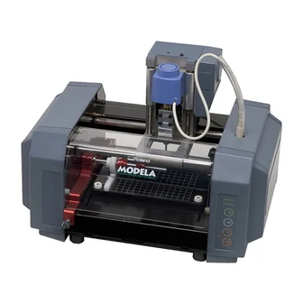
MDX-20
MDX-15
USER'S MANUAL
This User's Manual is intended for MDX-20 and MDX-15.
Thank you very much for purchasing the MDX-20/15.
To ensure correct and safe usage with a full under-
standing of this product's performance, please be sure
to read through this manual completely and store it in
a safe location.
Unauthorized copying or transferral, in whole or in
part, of this manual is prohibited.
The contents of this operation manual and the specifi-
cations of this product are subject to change without
notice.
The operation manual and the product have been
prepared and tested as much as possible. If you find
any misprint or error, please inform us.
Roland DG Corp. assumes no responsibility for any
direct or indirect loss or damage which may occur
through use of this product, regardless of any failure
to perform on the part of this product.
Roland DG Corp. assumes no responsibility for any
direct or indirect loss or damage which may occur with
respect to any article made using this product.
Advertisement
Table of Contents

Related Manuals for Roland MODELA MDX-15


Summary of Contents for Roland MODELA MDX-15
- Page 1 If you find any misprint or error, please inform us. Roland DG Corp. assumes no responsibility for any direct or indirect loss or damage which may occur through use of this product, regardless of any failure to perform on the part of this product.
- Page 2 ROLAND DG CORPORATION 1-6-4 Shinmiyakoda, Kita-ku, Hamamatsu-shi, Shizuoka-ken, 431-2103 JAPAN The authorized representative in the EU: Roland DG Corporation, German Office Halskestrasse 7, 47877 Willich, Germany For EU Countries WARNING This is a Class A product. In a domestic environment this product may cause radio interference in which case the user may be required to take adequate measures.
-
Page 3: Table Of Contents
Table of Contents To Ensure Safe Use ....................... 3 About the Labels Affixed to the AC Adapter and Unit ....................5 1 What You Can Do with MODELA ..................... 6 2 Check the Included Items ......................7 3 Part Names ..........................8 4 Setting Up and Connection ...................... - Page 4 AutoCAD® is registered trademark of Autodesk, Inc. IBM is trademark of International Business Machines Corporation. Other company names and product name are trademarks or registered trademarks of their respective holders.. Copyright © 2000-2012 Roland DG Corporation http://www.rolanddg.com/ Table of Contents...
-
Page 5: To Ensure Safe Use
Immediately unplug the power-cord plug Failure to do so may re- from the electrical outlet, and contact your sult in falling of the unit, authorized Roland DG Corp. dealer or service leading to injury. center. To Ensure Safe Use... - Page 6 CAUTION CAUTION Wear dust goggles D u r i n g c u t t i n g o r and mask during use. scanning, do not place Cutting dust may scat- hands near the cutting ter, causing bodily in- tool or the probe.
-
Page 7: About The Labels Affixed To The Ac Adapter And Unit
About the Labels Affixed to the AC Adapter and Unit These labels are affixed to the body of this product and the AC adapter. The following figure describes the location. Rated power supply Do not use with any electrical power supply that does not meet the ratings displayed on During cutting or scanning, the AC adapter. -
Page 8: What You Can Do With Modela
1 What You Can Do with MODELA Cut material to make a shape MODELA cuts materials for three-dimensional objects made with software. You can also engrave plates using flat line-drawing data. Create three-dimensional data from a shape MODELA can scan the shape of a solid object and create three-dimensional data. You can use this data to do things like changing the size or make use of a natural shape as part of another design. -
Page 9: Check The Included Items
2 Check the Included Items AC adapter: 1 Power cord: 1 Roland software package: 1 Spindle unit: 1 (*1) Sensor unit: 1 (*1) Cap screw M4 x 15: 4 (Two spares) The configuration o f t h e M DX- 1 5... -
Page 10: Part Names
3 Part Names NOTICE • Do not touch the wire with the hands. • Except when repacking the unit, do not attempt to move the table or carriage by hand. In this manual, sections that explain commons points for the MDX-20/15, use only illustrations of the MDX-20. Some details of the MDX-15 differ from the figure. -
Page 11: Setting Up And Connection
4 Setting Up and Connection WARNING Do not use with any power supply other than the dedicated AC adapter. Use with any other power supply may lead to fire or electrocution. WARNING Do not use with any electrical power supply that does not meet the ratings dis- played on the AC adapter. -
Page 12: Connecting With Computer
Connecting with Computer Serial connector IBM PC or PC compatible Serial cable (XY-RS-34 or equivalent) If your computer is an IBM PC compatible personal computer, then use an optionally available XY-RS-14/34 cable (or equivalent). A straight cable such as modem cable will not work. ... -
Page 13: Installing The Software
This sets the required parameters for cutting solid objects and sends the cutting data to MODELA. MODELA This can import not only solid objects created with three-dimensional programs from Roland DG Player Corp., but also solid objects created using other commercially available three-dimensional programs (via DXF or STL). -
Page 14: Setting Up The Program
If you are installing under Windows NT 4.0/2000/XP, log on to Windows as "Administrators" account. Switch on the computer and start Windows. Place the CD from the Roland Software Package in the CD-ROM drive. The Setup menu appears automatically. Click the drop-down arrow next to [Click here], choose the model you're using, then click [Install]. -
Page 15: Changing The Port
"MDX- 15" instead. Driver for Windows 95/98/Me Click [Start]-[Settings]-[Printer] to open the [Printer] folder. Right-click on the Roland MODELA MDX- 20 icon, then click [Properties]. The [Roland MODELA MDX-20 Properties] dialog box appears. ... - Page 16 Windows XP: Click [Start]-[Control Panel]. Click [Printers and Other Hardware], then click [Printers and Faxes]. Right-click on the Roland MODELA MDX-20 icon, then click [Properties]. The [Roland MODELA MDX-20 Properties] dialog box appears. Click the [Ports] tab. For [Port], choose an unused port other than [COM1].
-
Page 17: Application Settings
Click [MDX-20], then click [OK]. From the [File] menu, click [Print Setup...]. The [Print Setup] dialog box appears. Click the drop-down arrow for the name and click [Roland MODELA MDX-20]. Then click [OK]. Dr.PICZA Click [Start]. Point to [Roland Dr.PICZA] and click [Dr. - Page 18 To perform scanning, you need to temporarily set the Windows driver printer port to a different port. After you finish scanning, return the setting for the Windows driver to its original value. Dr.Engrave Click [Start]. Point to [Roland Dr.Engrave] and click [Dr. Engrave]. From the [File] menu, click [Print Setup...].
- Page 19 Click the drop-down arrow for the name and click [Roland MODELA MDX-20]. Then click [OK]. 3D Engrave Click [Start]. Point to [Roland 3D Engrave] and click [3D Engrave]. From the [Cut] menu, click [Machines...]. The [Model Selection] dialog box appears.
-
Page 20: How To Use Help
How to Use Help If you have trouble using the program or driver, see the help screens. Help contains information such as descriptions of software operation, explanations of commands, and tips for using the software more effectively. From the [Help] menu, click [Contents]. ... -
Page 21: Operation Guide [Cutting Section]
6 Operation Guide [Cutting Section] This section provides a step-by-step explanation of the basic procedures for cutting a solid objects with MODELA. In this section, it is assumed that you have already completed making the three-dimensional data for the solid object. It is assumed that the three-dimensional data you have prepared is three-dimensional data in DXF format. - Page 22 Make the settings for the cutting condi- tions. Clicking [NEXT] advances the setting screens in sequence from A to D. Make the settings in order from A to D. (Clicking A, B, C, or D in the figure displays the corresponding setting screen, this should not be used except when it's necessary to make settings independently.)
- Page 23 Checking the Cutting Results If Virtual MODELA is installed and set up, then before you perform actual cutting with MODELA you can check the shape that will be produced after cutting. From the [File] menu, click [Print Preview]. Virtual MODELA starts. ...
-
Page 24: Attach The Spindle Unit
Attach the Spindle Unit CAUTION During cutting or scanning, keep hands away from the cutting tool and the probe. Doing so may result in injury. NOTICE Attach the spindle unit securely so that it does not come loose during cutting. Before attaching the spindle unit, make sure the power to the Modela is switched off. -
Page 25: The Mounting Locations For The Spindle Unit
Make sure the tube is at the position shown in the figure. Insert the cord for the spindle unit into the jack. Tube Make sure it is at the base of the cord. Position the connector so the arrow points to the back of the unit and insert. -
Page 26: Install The Cutting Tool
Install the Cutting Tool CAUTION Do not touch the tip of the cutting tool with your fingers. Doing so may result in injury. NOTICE Attach the cutting tool securely so that it does not come loose during cutting. To install a cutting tool, remove the spindle. It’s not necessary to remove the whole spindle unit. ... - Page 27 Use a hexagonal wrench (size : 1.5 mm) to attach the included set screws to one side only. * Insert the set screw straight and install. Set screw Fit the spindle into place as shown in the figure. ...
-
Page 28: Maximum Cutting Area Of The Modela
Maximum cutting area of the MODELA Z-direction Bottom surface of the carriage 62.4 mm (2-7/16 in.) Workpiece thicker than this value cannot be loaded. In actual use, the thickness of the load- able workpiece varies according to the length of the mounted tool and the thick- ness of the base. -
Page 29: Attach The Front Cover
Apply double-sided tape to the workpiece. Make the adhesive surface broad so that the workpiece does not come loose during cutting. With a block like that in the figure, for example, apply the tape so there are no gaps on any side. Double-sided Workpiece tape... -
Page 30: Powering On
Powering ON NOTICE Before switching on the power to the MODELA, turn on the computer. Press the STANDBY key. The STANDBY LED lights up. The unit performs initial operation and stops, and the VIEW LED and MODELING MODE LED light up. * During initial operation, a sound may be heard for some 20 seconds at the time of origin detection. - Page 31 Cut the surface of the loaded workpiece to eliminate unevenness and create a level surface. This is called "surfacing." Set the Depth-direction Reference point Set the depth-direction reference point on the top surface of the workpiece. MODELA takes the position of the tool just before starting cutting as the depth-direction reference point. * You cannot set this while the VIEW LED is lit or during cutting.
- Page 32 From the [Options] menu, click [Layout...]. The [Layout/Surfacing] dialog box appears. The blue rectangle is the range of the object. When you double-click one of the black circles displayed at the corners of the object, the cutting tool descends to the depth-direction reference point at that location.
- Page 33 Press the TOOL-UP key to move the cutting tool away from the workpiece. In MODELA Player's [Layout/Surfacing Settings] dialog P l a c e c u t box, In the dialog box, drag the white circle to move it deeper than next to the black circle where you performed cutting in the surface...
- Page 34 Enter the surfacing depth. Here you set the cutting depth from the depth direction reference point. To change the range and location for surfacing, clear the selection for [Automatic]. To change the range, drag the solid squares surrounding the shaded area, or type in numerical values for [Width] and [Length].
-
Page 35: Perform Cutting
Perform Cutting A three-dimensional object is cut in two stages: draft cutting and finishing. First pass Draft cutting High-speed cutting that leaves a margin for finishing Second High-precision cutting of the margin on the workpiece surface left by draft cut- Finishing pass ting... -
Page 36: When Cutting Is Finished
Double-click the printer icon for the machine you're us- ing. If you're using the MDX-20, double-click the [MODELA MDX-20] icon. If you're using the MDX- 15, double-click the [MODELA MDX- 15] icon. At the [Printer] menu, choose [Purge Print Jobs] or [Cancel] to stop sending data. If you're using Windows 2000/XP, choose [Cancel All Documents]. - Page 37 Remove fallen cuttings from around the workpiece and the table. Other cuttings Metal cuttings Remove using a commercially available Remove using a commercially brush or with a vacuum cleaner. available brush. Remove any buildup of cuttings from under the table. Metal cuttings Detach the work plate.
-
Page 38: Operation Guide [Scanning Section]
7 Operation Guide [Scanning Section] Step 1: Attach the Sensor Unit NOTICE Attach the sensor unit securely so that it does not come loose during cutting. Perform installation and removal of the sensor unit while the cover is attached. If the cover is not present, the probe may be damaged if the sensor unit should fall or be dropped. - Page 39 While gently pressing down on the cover with one hand, loosen the screw shown in the figure. Screw Cover Pull the cover back to remove it. Make sure the tube is at the position shown in the figure. Insert the plug for the sensor unit into the jack.
-
Page 40: Step 2: Load The Object To Be Scanned On The Modela
Detaching the Sensor Unit Fit the cover onto the sensor unit as shown in the figure. Sensor unit Sensor unit Cover Cover Fit the notch in the cover into the area shown by slanted lines. While gently pressing down on the cover with one hand, tighten the screw shown in the figure. - Page 41 Maximum scanning area of the MODELA The maximum scanning area is shown in the figure. MDX-20 : 203.2 mm (8 in.) Maximum scaning area MDX-15 : 152.4 mm (6 in.) MDX-20 : 152.4 mm (6 in.) MDX-15 : 101.6 mm (4 in.) 60.5 mm (2-3/8 in.) Work plate 1 mm (0.0394 in.)
-
Page 42: Step 3: Attach The Front Cover
Install the work plate on MODELA and tighten the screws. Press in all the way, until flush. Step 3: Attach the Front Cover Attach the front cover. Fit the cover plate into place from above so that it goes into the portion shown in the figure. -
Page 43: Step 5: Setting Scanning Conditions And Starting Scanning
Step 5: Setting Scanning Conditions and Starting Scanning About scanning conditions and the scanning area Workpiece Scanning Area Y SCAN PITCH plate (Spacing of adjacent scan points along the Y axis) Scanning area Z Upper Limit X SCAN PITCH : Scan path (bidirectional scanning) Scan object (Spacing of adjacent scan... -
Page 44: Step 6: Setting The Scanning Area
Make the selection for scanning quality. Select [Smart Scan]. When this is selected, MODELA identifies and limits the scanning area before performing scanning (X and Y directions only). To specify the scanning area manually, deselect [Smart Scan], then click [Set Scanning Area]. For more information on how to specify this, see “Setting the Scan- ning Area”... - Page 45 Make the settings for the scanning area. Make the settings to match the location where the scan object is secured in place. Either of the following two methods can be used to make the settings. - Use the mouse to move the blue - Enter the numerical values for the frame on screen.
-
Page 46: Step 7: Saving Scanned Data
Cancels scanning/Pauses scanning Scanning pauses and the table moves toward the front of Cancels scanning. the unit. Click [VIEW] Any data scanned again to resume scan- before being canceled ning. remains in memory. Step 7: Saving Scanned Data Click and choose [Save]. -
Page 47: Overview Of The Usage Guides
8 Overview of the Usage Guides Overview of the Usage Guides The included Roland Software Package CD-ROM contains the following PDF files. - Cutting Tips This describes tips and tricks for double-sided cutting and methods for securing the workpiece in place. -
Page 48: Software Guide
Right-click on the [Roland MODELA MDX-20] icon, then click [Properties]. Method 2 From the [File] menu, click [Print Setup...]. The [Print Setup] dialog box appears. Set the printer to [Roland MODELA MDX-20], then click [Properties]. 9 Software Guide... - Page 49 Enter the Cutting Area Enter the size of the plate installed on MODELA. Click the [Size] tab. Enter values for [Width] and [Length]. Set the Engraving Parameters Make the settings for the composition of the workpiece to engrave and the engraving depth. Choosing the composition sets engraving parameters suited to this engraving.
-
Page 50: Driver For Windows Nt4.0/2000/Xp
Click [Start]-[Control Panel]. Click [Printers and Other Hardware], then click [Printers and Faxes]. Windows NT4.0: Right-click the [Roland MODELA MDX-20] icon, then click [Document Defaults]. Windows 2000/XP: Right-click the [Roland MODELA MDX-20] icon, and click [Printing Preferences]. Then, click [Advanced]. - Page 51 From the [File] menu, click [Print Setup...]. The [Print Setup] dialog box appears. Set the printer to [Roland MODELA MDX-20], and click [Properties]. If you're using Windows 2000/XP, then click [Advanced]. Enter the Cutting Area Enter the size of the plate installed on MODELA.
-
Page 52: Modela 3D Design
Double-click any tool from 1 to 4 to display the lower level. Click [Material], then click the composition of the engraving material (workpiece). Double-click [Color] to display the lower level. Click the color to set, then click the tool number. If you don’t wish to engrave lines of that color, click [None]. - Page 53 Click the basic shape that is closest to the finished form. Enter the size, then click [OK]. Decide on the number of reference lines The reference lines are control rods for arranging the shape of the object. To determine the number of reference lines, click the controls shown below. : 4 lines : 7 lines : 10 lines...
- Page 54 To change the centerpoint of the outer perimeter, click and drag the reference line. Check the shape Click the The [Rendering] dialog box appears. Drag the scroll box for the X, Y, or Z scroll bar. The object rotates, letting you view it from various perspec- tives.
-
Page 55: Modela 3D Text
When this is selected, dragging This changes the point of view. a reference line changes the size of the outer perimeter. When this is selected, dragging a This adds color and shadowing reference line moves the center- to the object's surfaces. point of the outer perimeter. -
Page 56: Modela Player
Save the data Click the The [Save As] dialog box appears. Enter the name of the file and click [Save]. Description of Controls This opens new file. This lets you choose the color of the ob- ject from among ten available colors. This opens an existing file. - Page 57 Switching the Screen Between Flat and Three-dimensional Views During Simulation • Clicking switches from a flat view to a three-dimensional view. When this button is selected, the view is three-dimensional during and after simulation. • Clicking switches from a three-dimensional view to a flat view. When this button is selected, the display shows a view of the workpiece as seen from above during and after simulation.
-
Page 58: Dr.picza
This displays a prediction of how This enlarges or reduces what much time cutting will take. The is displayed to fill the drawing time is a general estimate. size. In addition to the time, you can also verify the tool movement distance and movement range. -
Page 59: Dr. Engrave
From the [File] menu, click [Print Setup...]. The [Print Setup] dialog box appears. Make sure [Roland MODELA MDX-20] is specified as the printer, then click [Properties]. The [Roland MODELA MDX-20] dialog box appears. Enter the size of the plate, then click [OK]. - Page 60 Draw a Shape Click on the shape-drawing controls to draw the shapes. Change the Size and Location of a Shape or Text Click , then click the shape or text. Solid square ( ) and triangle ( ) pointers appear around the shape or text. To change the size, drag the pointers. <Changing the Size>...
- Page 61 Save the Data Click the The [Save As] dialog box appears. Enter the name of the file and click [Save]. Start Engraving Click the The [Save As] dialog box appears. To start engraving with MODELA, click [OK]. Description of Controls This opens new file.
-
Page 62: Engrave
3D Engrave This adds thickness to a flat (two-dimensional) graphic to create a relief (raised engraving). You can also add thickness to images such as illustrations. 3D Engrave is a program for creating reliefs (raised engravings) and engravings on curved surfaces. This section describes the steps for cutting a relief. - Page 63 Create a Raised Engraving (Relief) Add thickness to shapes and text to create a relief. Click the shape or text string you want for adding thickness to select it. Click the The [Relief Size] dialog box appears. The dialog box may differ depending on the type of object you selected. The following screen shows the dialog box that appears when creating a relief of shapes or text.
- Page 64 Creating a Tool Path A tool path is the path followed by the tool's tip. The tool path is generated from the cutting parameters that are presently set. Before you create the tool path, make the settings for the cutting parameters. At the cutting parameters, make the settings for the composition of the workpiece, the type of tool, and the cutting process.
- Page 65 Save the Data Click the The [Save As] dialog box appears. Enter the name of the file and click [Save]. Start Engraving Click the When the screen at right appears, click [OK]. Cutting with MODELA starts. Description of Controls This opens new file. This types in the text This opens an existing file.
- Page 66 For China 产品中有毒有害物质或元素的名称及含量 有毒有害物质或元素 部件名称 六价铬 多溴联苯 多溴二苯醚 铅(Pb) 汞(Hg) 镉(Cd) (Cr(Ⅵ)) (PBB) (PBDE) 印刷电路板 × ○ × ○ ○ ○ 头部 × ○ ○ ○ ○ ○ 壳体、底架 × ○ ○ ○ ○ ○ 电源 × ○ × ○ ○...
-
Page 67: What To Do If
10 What to Do If... The MODELA doesn't operate Is the STANDBY key on? Press the STANDBY key. Has operation not been paused by pressing the VIEW key (lighting up the VIEW LED)? Press the VIEW key to cancel the View state. Are the cable connected correctly? Check the output ports for MODELA and the computer and make sure they are connected correctly. - Page 68 If there is an obstruction, then switch off the power, remove the obstruction, and switch the power back on. If there was a hardware error, then switch the power off and back on and repeat the same operation. If the same error display occurs, consult your authorized Roland dealer or service center. Unexpected Program Operation I can't open a file.
-
Page 69: Items That May Not Be Copied
Unauthorized reproduction of a copyrighted item for any purpose other than personal use may be a violation of copyright. Roland DG Corp. will not be responsible for any violation of third-party copyright by any article made through use of this product. -
Page 70: Specifications
35 to 80 % (no condensation) Accessories AC adapter: 1, power code: 1, Roland Software Package CD-ROM: 1, spindle unit: 1, sensor unit: 1, cap screw M4x15: 4, tool:1, set screw M3x3: 2, double-sided tape: 1, front cover: 1, hexagonal wrench (size : 3 mm) :1, hexagonal wrench (size : 1.5 mm):... -
Page 71: Interface Specification
Interface Specification [Serial] Standard RS-232C specifications Transmission method Asynchronous, duplex data transmission Transmission speed 9600 bps Parity Check None Data Bits 8 bits Stop Bits 1 bits Handshake Hardware Serial connector (RS-232C) Signal Terminal Signal Pin connection number number number 12 Specifications... -
Page 72: Please Read This Agreement Before Unpacking The Media
Please read this Agreement before unpacking the media. Software license agreement Roland DG Corporation (hereinafter referred to as the “Company”) shall grant you a non-transferable, nonexclusive right to use the Software supplied with this Agreement, on the condition that you agree to the following provisions.