Table of Contents
Advertisement
Quick Links
Advertisement
Table of Contents

Related Manuals for Bosch DDU 10


Summary of Contents for Bosch DDU 10
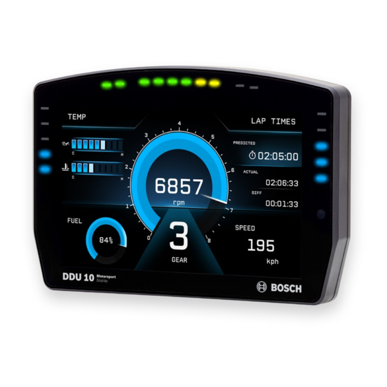
- Page 1 Display DDU 10 Manual Version 1.0 14/03/2019...
-
Page 2: Table Of Contents
11.2 Element Configuration ....................................... 11.3 Types of display elements....................................11.4 Context menu ........................................11.5 LEDs ............................................11.6 Page select / Display brightness / LED brightness ..........................11.7 Alarms ............................................11.8 User Interface Menu UIM ....................................ii / 188 DDU 10 Bosch Motorsport... - Page 3 21.2 Functionality and channel outputs ................................22 GPS Sensor..................................22.1 GPS (Global Positioning System)..................................22.2 Protocol ............................................ 22.3 Sensor recommendation ....................................22.4 Measurement labels ......................................22.5 GPS troubleshooting......................................23 Firmware ..................................23.1 Firmware and configuration ..................................... 23.2 Firmware update........................................Bosch Motorsport DDU 10 iii / 188...
- Page 4 Content 24 Clone the Unit ................................. 25 Fuel Consumption Calculation ............................25.1 Setting up fuel consumption calculation and tank management ..................... 25.2 Fuel consumption diagnosis/counter reset..............................25.3 Example ............................................ 26 RaceCon Shortcuts................................iv / 188 DDU 10 Bosch Motorsport...
-
Page 5: Onboard Network Concept
(e.g. wheelspeed) SENSPWR5 As short as possible active ANA_IN(xy) LS_GND_1 Sensor LS_GND_2 ANA_IN(xx) Sensor Engine_GND SENSGND NOTICE This schematic is not device specific, please see the section “Technical Data for the spe- cifications of your device. Bosch Motorsport DDU 10 5 / 188... -
Page 6: Preparation
2 | Preparation 2 Preparation Use the DDU 10 only as intended in this manual. Any maintenance or repair must be per- formed by authorized and qualified personnel approved by Bosch Motorsport. Operation of the DDU 10 is only certified with the combinations and accessories that are specified in this manual. -
Page 7: Power Supply
– KL 30 is an unswitched battery positive rail (same as battery positive terminal) – KL 31 is an unswitched ground rail (same as battery negative terminal) Be careful to observe current limits of wires and connector pins! Bosch Motorsport DDU 10 7 / 188... -
Page 8: Starting Up
– The ethernet port has “cable auto crossover” functionality 4.1.1 Starting the unit The DDU 10 powers up by turning on the ignition of the car. At startup the DDU 10 will display a Bosch logo. After a moment the DDU 10 shows a display element screen. - Page 9 Troubleshooting while setting up the network interface The DDU 10 contains a DHCP server, network addresses can be assigned automatically to the configuration PC. In case of problems during the network connection, please try the following steps: Switch off the PC’s firewall.
- Page 10 Start the RaceCon software. In the ‘File’ menu select ‘New project’ to create a new project. In the Toolbox select the DDU 10 and drag it into the Main Area. A pop up window to specify the DDU 10 program archive appears.
- Page 11 An information shows if the archive is valid or not. Click ‘Next’. Select ‘Race track’ or ‘Testbench’ mode according to your application. Click ‘Finish’. The DDU 10 is inserted into the project and RaceCon tries to connect to the device. Bosch Motorsport DDU 10 11 / 188...
- Page 12 4 | Starting up RaceCon detects configuration differences between the DDU 10 and the RaceCon project and asks for permission for data download. Click ‘Yes’ to download the configurations to the device or ‘No’ to continue without downloading the data.
-
Page 13: First Display Configuration (Quick Start)
Starting up | 4 After the reset, RaceCon reconnects to the DDU 10. Local configuration on both the PC and DDU 10 match (indicated by green background and dot). The DDU 10 is now connected to RaceCon. Green background and dot indicate... - Page 14 Use the search bar in the ‘Data’ window, to search for ‘ub’ (measurement channel for battery voltage). Search for 'ub' Drag the ‘ub’ measurement channel from the ‘Data’ window and drop it on the dis- play element. 14 / 188 DDU 10 Bosch Motorsport...
-
Page 15: First Recording (Quick Start)
Drag + Drop Click on the ‘Download’ button in the upper left corner. The configuration download starts and the DDU 10 carries out a reset. The status sig- nal in the upper left corner switches to green. The value of the battery voltage is displayed on the DDU 10. - Page 16 Drag + Drop Click on the ‘Download’ button in the upper left corner. The configuration download starts and the DDU 10 carries out a reset. Now you can find the ‘ub’ measurement channel in the ‘Data Area’. As we did not define global start conditions, recording starts immediately.
- Page 17 Starting up | 4 Disconnect the DDU 10 network cable. Click on the ‘Read Data from Logging Device’ icon. Choose your logger and click ‘OK’ when done. Click 'read data from logging device' The ‘Data Logger Import’ dialog opens. NOTICE Refer to the WinDarab V7 manual for instructions on how to use the ‘Data Logger Import’...
- Page 18 12. Click on the ‘Current Import’ tab. 13. Click on ‘Import’ in the lower right corner. If the ‘Import all on connect’ box is checked, the data transmission from the DDU 10 starts automatically. Measurement files are stored automatically in the folder defined under ‘Settings’.
-
Page 19: Feature Activation
– The feature activation status is stored permanently in the device and requires activat- ing once only. – As the activation key is device specific, a key delivered with one DDU 10 does not work on any other DDU 10 . - Page 20 Enter the activation key you received for this feature on this device and click ‘OK’ when done. The feature’s status changes to ‘unlocked’. Perform these steps to activate other features you purchased. Switch the car’s ignition off and on again to cycle the power of DDU 10. 20 / 188 DDU 10...
-
Page 21: Set Time And Date
Starting up | 4 4.5 Set time and date The DDU 10 is equipped with a real time clock which is supplied by an internal accumu- lator. Once this accumulator is charged correctly by 12 V supply of the display, ‘Date &... -
Page 22: Color Indication
– As a background, as well as a little dot around the display icon in the ‘System win- dow’. – As a colored stripe beside the device name in the project tree. – As a colored background around the device name in the project tree. 22 / 188 DDU 10 Bosch Motorsport... - Page 23 – Black MIL: No errors. – Orange MIL: Inactive Errors (Error entries existing, but not longer active). – Blinking MIL (orange/black): Active Errors. For further information, see chapter Error Memory Properties [} 57]. Bosch Motorsport DDU 10 23 / 188...
-
Page 24: Export And Import In Racecon
Click with the right mouse button on any item in the project tree. Select ‘Import…’ from menu. A file browser opens. Select the input file and click ‘Open’. An ‘Import Selection’ window opens. Select channels to import. 24 / 188 DDU 10 Bosch Motorsport... - Page 25 Drag and drop the channel to ‘CAN Input’ of desired CAN bus on right hand side. Click ‘Finish’. If a measurement channel belongs to more than one source (e.g. DDU 10 and MS 5.1), the ‘Solve Label Ambiguity’ window opens. Assign the ambiguous channels to the desired source. Click ‘Finish’. Bosch Motorsport DDU 10 25 / 188...
-
Page 26: Analog And Frequency Inputs
Filtered physical value Filtered channels are routed through digital low pass filters: – DDU 10 uses A/D converter oversampling and digital filtering to recording rate – Digital filters eliminate ‘out-of-band’ noise – Cut-off frequency automatically adjusted to recording rate –... -
Page 27: Configuring Inputs
'Bosch Sensor Wizard' Click on ‘Measurement Sources’ in the Toolbox. To expand the list of ‘I/O Channels’, click on ‘+’ in the DDU 10 Project Tree. Drag the “Bosch Sensor Wizard” from the Toolbox and drop it on the desired analog input channel in the DDU 10 Project Tree. - Page 28 Click ‘Finish’ when done. The “Create channel” window opens. Enter the channel name and description. Click ‘Ok’ when done. The channel is inserted into the DDU 10 Project Tree. Channel is linked to ANA03 Calculation of Input pin Pull-up...
- Page 29 To activate the internal pullup-resistor, check the box. The internal pullup-resistor is used to get a 5 V signal at the analog channel of the DDU 10. It allows you to use a push-button. The fixed value of the internal pullup-resistor is 3,010 Ohm. If using an additional external pullup-resistor, set up the overall resistance.
- Page 30 Working with automatically created measurement sheets is ex- plained in chapter ‘Setting up an online measurement [} 46]’. Click ‘Finish’ when done. Enter a channel name and a description. Click ‘OK’ when done. The channel is inserted into the DDU 10 Project Tree. 30 / 188 DDU 10 Bosch Motorsport...
- Page 31 Thermistor Click ‘Measurement Sources’ in the Toolbox. To expand the list of ‘I/O Channels’, click on ‘+’ in the DDU 10 Project Tree. Drag the “Characteristic Curve” analogue signal source from the Toolbox and drop it on the desired analogue input channel in the DDU 10 Project Tree.
- Page 32 To activate the internal pull up-resistor, check the box. The DDU 10 pull up-resistor is used to get a 5 V signal at the analogue channel of the DDU 10. It allows you, to use a push-button. The fixed value of the internal pull up-resistor is 3,010 Ohm. If using an additional external pull up-resistor, set up the overall resistance.
- Page 33 Click ‘Finish’ when done. Enter channel name and description. Click ‘OK’ when done. The channel is inserted into the DDU 10 Project Tree. Channel is linked to ANA05 Characteristic Adjustment curve for sensor is disabled...
- Page 34 – Curve definition by online adjustment at vehicle Click on ‘Measurement Sources’ in the Toolbox. Expand the list of ‘I/O Channels’ by clicking on ‘+’ in the DDU 10 Project Tree. Drag the ‘Multipoint Adjustment’ analog signal source from the Toolbox and drop it on the desired analog input channel in DDU 10 Project Tree.
- Page 35 To activate the internal pullup-resistor, check the box. The internal pullup-resistor is used to get a 5 V signal at the analog channel of the DDU 10. It allows you to use a push-button. The fixed value of the internal pullup-resistor is 3.01 kOhm. If using an additional external pullup-resistor, set up the overall resistance.
- Page 36 Click ‘Finish’ when done. Enter channel name and description. Click ‘OK’ when done. The channel is inserted into the DDU 10 Project Tree. Channel is linked to ANA06 Characteristic Adjustment curve for sensor is enabled...
- Page 37 Online definition of the curve is covered in the chapter ‘Online calibration of measurement channels [} 51]’ of this manual. NOTICE Working with automatically created measurement sheets is ex- plained in chapter ‘Setting up an online measurement [} 46]’. Bosch Motorsport DDU 10 37 / 188...
- Page 38 6 | Analog and Frequency Inputs 6.2.5 Digital filter details DDU 10 uses A/D converter oversampling and digital filtering to recording rate. Digital filters eliminate ‘out-of-band’ noise Cut-off frequency automatically adjusted to recording rate Example: – 100 Hz recording rate (10 ms) –...
- Page 39 – Calculation of wheel speed with wheel circumference Click on ‘Measurement Sources’ in the Toolbox. To expand the list of ‘I/O Channels’, click on the ‘+’ in the DDU 10 Project Tree. Drag the ‘Velocity’ digital signal source from the Toolbox and drop it on the desired ‘REV’...
- Page 40 Enter name to automatically create a new measurement sheet Click ‘Finish’ when done. Enter the channel name and description. Click ‘OK’ when done. The channel is inserted into the DDU 10 Project Tree. Channel is linked to REV01 Input pin Number of...
-
Page 41: Configuring Computed Sources
Example: Sensitivity/offset calculation on input channel Click ‘Measurement Sources’ in the Toolbox. Drag the ‘Sensitivity/Offset’ computed source from the Toolbox and drop it on ‘Com- puted Channels’ in the DDU 10 Project Tree. Drag + Drop A ‘Computed Sensitivity/Offset Wizard’ opens. -
Page 42: Hysteresis
Click ‘Finish’ when done. Enter channel name and description. Click ‘OK’ when done. The channel is inserted into the DDU 10 Project Tree. NOTICE Working with automatically created measurement sheets is ex- plained in chapter ‘Setting up an online measurement’. - Page 43 Enter name to automatically create a new measurement sheet Click ‘Finish’ when done. Enter channel name and description. Click ‘OK’ when done. The channel is inserted into the DDU 10 Project Tree. Channels available in Computed sources Calculation of hysteresis channel...
- Page 44 Click on ‘Measurement Sources’ in the Toolbox. Drag the ‘Speed’ computed source from the Toolbox and drop it on the project name in the DDU 10 Project Tree. Do not drop it on ‘DDU 10’! Drag + Drop A ‘Calculated Speed Wizard’ opens.
- Page 45 Choose driven axle Choose individual wheel speed channels Set limit for speed difference for calculation Click ‘Finish’ when done. The speed calculation is inserted into the DDU 10 Project Tree. Speed calculation in DDU Project Tree Measurement channels calculated speed...
-
Page 46: Online Measurement
DDU 10 configuration – System configuration (channel + display configuration, CAN I/O, etc.) is stored in the DDU 10 – Use RaceCon to create and download configuration from the PC to DDU 10 Commu- nication interface: Ethernet – Communication protocol: XCP Online measurement + calibration –... - Page 47 Drag a measurement element from the Toolbox and drop it on the measurement sheet. Drag + Drop Select the desired measurement channel from the ‘Data’ area and drop it on the measurement element. If the DDU 10 shows the green status, the value is displayed. Bosch Motorsport DDU 10 47 / 188...
- Page 48 Numeric indicator Oscilloscope (Chart) 7.1.1 Automatic creation of measurement sheets RaceCon can create measurement sheets automatically. You can create and use measurement sheets with the DDU 10 as well as with all other devices connected to RaceCon. 48 / 188 DDU 10...
- Page 49 During the configuration of a measurement channel, select a measurement sheet from the list box or enter a name for a new measurement sheet. Select existing sheet from list or enter name of new sheet Bosch Motorsport DDU 10 49 / 188...
- Page 50 The automatically created sheet is inserted in the Project Tree under ‘Measurement Container’ and ‘Device Channels’. If the DDU 10 is connected to RaceCon and the status is green, live values of the channels are shown. 7.1.2 Using the measurement sheets When RaceCon is online, press the ‘F11’...
-
Page 51: Online Calibration Of Measurement Channels
– Analog sensors drift with age, temperature, etc. – Manual calibration is necessary – Solution: online offset calibration – Example: acceleration sensor 7.2.1 Enable online offset calibration for measurement channel During creation of the measurement channel Bosch Motorsport DDU 10 51 / 188... - Page 52 7.2.2 Performing the online offset calibration DDU 10 has to be connected to RaceCon to calibrate the sensor’s offset. Apply the desired physical condition to the sensor (e.g. 1 G to an acceleration sensor). Open the measurement channel’s online page by double-clicking on the measure- ment channel name in the Data Area.
-
Page 53: Online Calibration Of Multipoint Adjustment Channels
Create a multipoint adjustment measurement channel. To create a multipoint channel, see chapter ‘Configuring a multipoint adjustment [} 34]’. Download the configuration on the DDU 10. To connect the DDU 10 to RaceCon, see chapter ‘Setting up a new RaceCon Project [} 9]’. - Page 54 7 | Online Measurement Press the ‘Calibrate’ button of the desired calibration point. Repeat for all curve points. 10. Click ‘Close’ when done. The calibration curve is displayed in the online view. Adjustment points vs. offset adjustment 54 / 188 DDU 10 Bosch Motorsport...
-
Page 55: Error Memory
DDU 8. Please consider this and replace the product name ‘DDU 8’ in this case with the name of your product. 8.1 Error memory representation in RaceCon Bosch Motorsport devices feature an error memory. Information on errors can be visual- ized via RaceCon (online measurement) or can be transmitted via telemetry. 8.1.1 Accessing the memory... - Page 56 The error memory is not cleared by a configuration download and is not cleared by a power cycle. 8.1.2 Clearing the error memory There are two ways of clearing the error memory, both are shown in the following illustra- tion: 56 / 188 DDU 10 Bosch Motorsport...
-
Page 57: Information On Errors Available From The Error Memory
1: at least one inactive error present in memory, no active errors 2: at least one active error present in memory If displayed in a measurement sheet, this property’s value (0, 1 or 2) is translated into a verbal description: Bosch Motorsport DDU 10 57 / 188... - Page 58 0 (no error present in memory): No orange border MIL off (black) No entries 1 (at least one inactive error present in memory, no active errors): Constantly orange border MIL constantly orange Info cycling through errors, present in error memory 58 / 188 DDU 10 Bosch Motorsport...
- Page 59 All failure modes are continuously diagnosed; any error detected will be written to the error memory. Once an error is detected, it is qualified as “active”. – 1 (TRUE) Error was detected in most recent diagnose run (active) Bosch Motorsport DDU 10 59 / 188...
- Page 60 (while more than one error is active) and watch the values change periodically: The verbal representation of the numerical codes of these labels can be visualized in the properties window of the measurement page: 60 / 188 DDU 10 Bosch Motorsport...
-
Page 61: Analog Input Diagnosis
The pin diagnosis functionality (check whether measurement is within the desired range) can be activated in the ANA pin setup wizard; to allow for a diagnosis regarding shortcut to ground, shortcut to battery voltage and cable breakage, a minimum / maximum has to be defined. Bosch Motorsport DDU 10 61 / 188... - Page 62 Open the Error Memory of the Device. Click "start detection of cable". Check the Error Memory for new fault entries, regarding "Open line errors". 62 / 188 DDU 10 Bosch Motorsport...
-
Page 63: Technical Data
The logger can be upgraded to full logging performance (max. 1 ms). In addition a 2nd logging partition of 1 GB can be activated. With the DDU 10, a completely new library of graphical elements for the individual design of display pages was implemented and an all-new user interface menu has been de- veloped for the device. - Page 64 6 steps Optional Upgrades USB_DATA USB-Port unlocked (Rugged USB flash drive Bosch File System (BFS) format in- cluded, works with Bosch File System (BFS) preformatted USB Flash drive only) Adapter cable to USB-Port included in Upgrade USB_DATA...
- Page 65 Sens_Gnd_4 fused Incl. Sens_Power 5V over current protected Incl. ANA_IN_3 3.01 kOhm switchable Incl. ANA_IN_4 3.01 kOhm switchable Incl. Time_Sync connection to Bosch ECU Incl. CAN_1_L CAN speed selectable Incl. Ethernet_screen Incl. Ethernet_2_RXN Incl. Sens_Gnd_3 fused Incl. Sens_Power 5V over current protected Incl.
- Page 66 Auxiliary connector Name Comment Status Unused Unused Unused Unused Unused Unused Unused Unused Ethernet_3_TXP Incl. Ethernet_3_RXP Incl. Ethernet_3_RXN Incl. CAN_4_H Opt. Unused Unused Unused Unused Unused Ethernet_screen Incl. Ethernet_3_TXN Incl. CAN_4_L Opt. CAN_3_H Opt. CAN_3_L Opt. 66 / 188 DDU 10 Bosch Motorsport...
-
Page 67: Mechanical Drawing
Mechanical Drawing | 10 10 Mechanical Drawing Bosch Motorsport DDU 10 67 / 188... -
Page 68: Display Configuration
11.1.2 Adding a new display page Click with the right mouse button on ‘Display’ in the project tree and click on ‘Add page’ in the menu or on the ‘Add’ button at the top. A new empty page opens. 68 / 188 DDU 10 Bosch Motorsport... -
Page 69: Element Configuration
(Only overlapping properties will be displayed.) You can find the following configuration options in the ‘Properties’ toolbox. The following screenshots are created by way of example for available options. Which options will be available, depends on which element is active: Bosch Motorsport DDU 10 69 / 188... - Page 70 – Active icon: Defines an icon, which appears when the channel is active. – Use inactive icon: Enables the usage of an inactive icon. – Inactive icon: Defines an icon, which appears when the channel is inactive. 70 / 188 DDU 10 Bosch Motorsport...
- Page 71 – Fill style: Defines the style of the bar filling. You can choose between blocks and solid. – Tick visibility: Defines the visibility of the ticks. – Minimum value: Defines the minimum value at which the counting starts. Bosch Motorsport DDU 10 71 / 188...
- Page 72 – Color border: Defines the new color of the border when the value is above/below the set threshold limit. – Background: Defines the color of the background when the value is above/below the set threshold limit. 72 / 188 DDU 10 Bosch Motorsport...
- Page 73 Value – Init value: Defines the value, which will be shown in RaceCon during configuration or on the device if the channel has no link. Allows testing the conditional formatting by entering a representative value. Bosch Motorsport DDU 10 73 / 188...
-
Page 74: Types Of Display Elements
Some of these are also transparent and can be used in combination with other elements by layering them. You can find the following display elements in the ‘Display Elements’ catalog: Classic Box Classic horizontal bar 74 / 188 DDU 10 Bosch Motorsport... - Page 75 Display Configuration | 11 Classic vertical bar Classic Gauge Large Classic Gauge Small Modern Box Modern horizontal Bar Bosch Motorsport DDU 10 75 / 188...
- Page 76 Modern Gauge Large Modern Gauge Small Basic Box Value / Text Can be used as a simple value or text element, which might be placed on top of another element, like the classic gauge large. 76 / 188 DDU 10 Bosch Motorsport...
-
Page 77: Context Menu
Manage overlapping elements Delete element 11.5 LEDs The LEDs are fully configurable to show for example the optimal shifting point. They can also be configured to flash in case of a customized condition becoming ‘true’. Bosch Motorsport DDU 10 77 / 188... - Page 78 Alternatively, click on the ‘Display’ tab and then click on the colored LEDs at the top of the display image. Tab 'Display' Tab 'LEDs' Click on the button ‘Add shift lights’. Button 'Add shift lights' 78 / 188 DDU 10 Bosch Motorsport...
- Page 79 2nd gear='2' = 50, ...). (ASCII quantization is standard for the 'gear' channel of Bosch ECUs. If you get the gear information of a different control unit as the Bosch ECU (e.g. a gearbox control unit), use the Gear Lookup Table to translate numeric values to ASCII format.
- Page 80 This column shows the ASCII value of the output channel Click ‘OK’ when done. The ‘Create channel on DDU 10’ window appears. Enter the name and an optional description of the translated ASCII measurement channel. e.g. 'gear ASCII' Click ‘Ok’ when done.
- Page 81 LEDs (right side of pattern is for the top LEDs), and for the LEDs on the right side the pattern starts at the top LEDs (left side of the pattern is for the top LEDs). Click ‘OK’ when done. Bosch Motorsport DDU 10 81 / 188...
-
Page 82: Page Select / Display Brightness / Led Brightness
11 | Display Configuration The configuration is displayed in the DDU 10 LED Configuration window. 11.5.4 Assigning display pattern priority You can assign the priority of the created display pattern and shift lights. The pattern with a higher priority will always cover patterns with a lower priority, when it becomes active. - Page 83 Connect a 6 or 12 position switch to one of the analog input pins ANAxx and to the sensor ground. For recommended position switches, please see the environment section in the chapter “Technical Data.” Select one of the analog inputs in the project tree. Bosch Motorsport DDU 10 83 / 188...
- Page 84 Go to ‘Measurement Sources’ in the toolbox and select the ‘Characteristic Curve’ un- der ‘Analog sources’. Drag and drop it on the selected analog input channel in the project tree. Select ”Pull-up value:” 3.01 kOhm and click on ‘Next’. 84 / 188 DDU 10 Bosch Motorsport...
- Page 85 R: Resistor for each Rotary switch position (Ohm) 3010: Pull-up resistor (Ohm) The following screenshot and the data are an example for a Bosch switch. Define minimum and maximum Limit. Select “Output data type” from 8, 16 or 32 Bit.
- Page 86 11 | Display Configuration Define Name and Description and click on ‘Ok’. Click on the ‘Display’ tab and select the ‘Settings’ tab at the bottom. 86 / 188 DDU 10 Bosch Motorsport...
- Page 87 You will see a graphical display with the raw and the physical value of the channel. 11.6.3 Option 2: Up/Down switches Define either one signal for a wrap around switch or two signals for an up/down switch. Select the ‘Display Switch’ and drag it into the DDU 10. Bosch Motorsport DDU 10 87 / 188...
- Page 88 (by switching) in a loop, after the last page it starts again with the first page. If you choose “Display switch does not wrap around”, you need two switches to turn the pages in both directions. Define Name and Description and click on ‘Ok’. 88 / 188 DDU 10 Bosch Motorsport...
- Page 89 Display Configuration | 11 In the project tree, select “Display” and then “Open”. To use the channel as a Page Switch, check the box "Use a channel to switch pages" and select the channel configured above. Bosch Motorsport DDU 10 89 / 188...
- Page 90 In the project tree, select “Download configuration”. If you want to check your configured channel, reassure that the device status is green, double-click on the DDU 10 and select the "Statistics" tab. The configured channel position opens. 90 / 188...
- Page 91 Display Configuration | 11 11.6.4 Option 3: CAN input signal, math channel or ANA_IN channel Define your CAN, math or analog input channel. Select the 'Display' tab and then the 'Settings' tab at the bottom. Bosch Motorsport DDU 10 91 / 188...
- Page 92 To use a channel as a Page Switch, check the box" Use a channel to switch page" and select the channel configured above. Click on the ‘Download’ button in the upper left corner. 92 / 188 DDU 10 Bosch Motorsport...
-
Page 93: Alarms
Select the “Alarm condition” channel, which will trigger the alarm when the channel becomes true. The “Alarm condition” channel can be any Boolean channel, like any other conditional channel. If desired, select a “Value Channel”. Bosch Motorsport DDU 10 93 / 188... - Page 94 – Retrigger lock enable: Enables the function “Retrigger lock”. For more details, see chapter Resettable Alarm [} 99]. – Retrigger lock time: Defines the time in which a new rising edge of the alarm condi- tion will not be accepted anymore, after an alarm was reset. 94 / 188 DDU 10 Bosch Motorsport...
- Page 95 – Color value: Defines the color of the value inside the alarm box. – Color box: Defines the color of the alarm box. Format – Text: Defines the Text and/or the value of the alarm. Bosch Motorsport DDU 10 95 / 188...
- Page 96 – Decimal places: Defines the decimal places, which should be displayed. Icon – Default icons: Defines the alarm icon, which should be displayed. – Default color: Defines the color of the icon. 96 / 188 DDU 10 Bosch Motorsport...
- Page 97 [} 42]. – Color value: Defines the color when the value is above/below the set threshold limit. – Color box: Defines the new color of the box when the value is above/below the set threshold limit. Bosch Motorsport DDU 10 97 / 188...
- Page 98 – Y-Pos: Defines the y-position of the top left corner of the alarm message within the alarm area. – Width: Defines the width of the alarm message. – Height: Defines the height of the alarm message. 98 / 188 DDU 10 Bosch Motorsport...
-
Page 99: User Interface Menu Uim
You can use the User Interface Menu (UIM) to conduct minor setting changes on the DDU, like lap time or fuel reset. How to configure the UIM Perform the following steps, to set up an UIM on your device: Bosch Motorsport DDU 10 99 / 188... - Page 100 – Outing counter increment Increments the outing counter by 1. – Lap counter increment Increments the lap counter by 1. – Lap distance reset Resets the traveled lap distance to zero. – Lap counter reset 100 / 188 DDU 10 Bosch Motorsport...
- Page 101 100 ms, when selected through the UIM. You can use such a channel for sensor calibration or any further custom calculation. A UIM configuration to change the current outing counter and to reset the best lap time could look like this: Bosch Motorsport DDU 10 101 / 188...
-
Page 102: Math Channels And Conditional Functions
Enter the formula. d) Select the logical operator. e) Choose a measurement channel. f) Define a value that can be used as a constant in the formula. g) Choose a function. h) Describes the function selected above. 102 / 188 DDU 10 Bosch Motorsport... - Page 103 Math Channels and Conditional Functions | 12 Click ‘Finish’ when done. The math channel is displayed in the DDU 10 math channel window. Conditional Function – Arithmetic and logical operations on one or more measurement channel(s) – If-Else structure with reset –...
- Page 104 An example of a condition to set up the maximum front brake pressure is given on the next page. The conditional function is displayed in the DDU 10 math channel window. Example: Setting up a condition for maximum front brake pressure Brake pressure front p_br_front Brake pressure ‘front p_br_front’...
- Page 105 – When ‘p_br_front’ rises to 40, the IF-condition changes to TRUE again and triggers the THEN-condition. Now the reset value (10) is used for ‘p_br_front_mx’ in the THEN- condition. – Because 40 is bigger than 10 the new value of ‘p_br_front_mx’ is 40. Bosch Motorsport DDU 10 105 / 188...
-
Page 106: Conditional Channels And Condition Combination
– Result can be used as input source for alarm display elements and further calculations in the whole RaceCon project. Creating a new Conditional Channel Follow the steps shown in the screenshot. The “Create/edit condition” window appears. 106 / 188 DDU 10 Bosch Motorsport... - Page 107 Conditional Channels and Condition Combination | 13 Define the condition channel, using the following configuration possibilities: Click ‘Ok’ when done. The conditional channel is displayed in the DDU 10 condition channel window. Condition Combination – Combination of several (up to 16) conditional channels for more complex calculations –...
- Page 108 – Pulse: Result is a short one-time pulse, if the condition is fulfilled. – Toggling output: Result is a pulse that lasts until the next condition is fulfilled. Click ‘Finish’ when done. The conditional combination is displayed in the DDU 10 con- dition channel window.
-
Page 109: Disposal
Hardware, accessories and packaging should be sorted for recycling in an environment- friendly manner. Do not dispose of this electronic device in your household waste. Waste electronic equipment must be disposed of properly according to Electrical and Electronics Act (ElektroG) and the European WEE directive. Bosch Motorsport DDU 10 109 / 188... -
Page 110: Cpu Load Limits
– Logger configuration (total logging rate [kB/s], conditional measurement rates) To help respecting the limit of 85 % CPU load, the DDU 10 creates an error memory entry. To trigger this error entry, the CPU load must exceed the limit for 5 minutes without inter- ruption. -
Page 111: Can Bus
CAN Bus | 16 16 CAN Bus The DDU 10 has four fully configurable CAN buses. Two of these are available as an up- grade. – Baudrate (250 kbaud , 500 kbaud, 1 Mbaud) – 11 Bit or 29 Bit identifiers –... -
Page 112: Can Input
16.2.1 Create new CAN Input channel Double-click on any CAN bus item, to open the "CAN messages overview". Select ‘Add CAN-IN’ and choose the desired CAN bus for the new input channel. A CAN channel configuration window opens. 112 / 188 DDU 10 Bosch Motorsport... - Page 113 CAN Bus | 16 Insert the name and description of the channel. Click ‘OK’ when done. The channel is listed in the Data window. Bosch Motorsport DDU 10 113 / 188...
- Page 114 Extracting data from CAN bus Representation: Byte Some CAN devices need to be addressed by a byte represented CAN channel. The ad- dress can be assigned in this window and is illustrated by a bar graph. 114 / 188 DDU 10 Bosch Motorsport...
- Page 115 Enter data position, length and format. e) The bargraph shows assignment of the bytes. - Red colored fields show the assignment of the data bytes. - Orange colored fields show the assignment of the multiplexer bytes. Bosch Motorsport DDU 10 115 / 188...
- Page 116 Special features CAN analyzer functionality This functionality is only available, if a MSA-Box (I or II) is used to connect the DDU 10 to the PC. Choose the CAN bus that is connected to the MSA-Box to display the raw value and the converted physical value here.
-
Page 117: Can Output
For an online view of the value measured by the DDU 10 , insert the channel in an online measurement sheet which is described in the chapter Setting up an online measurement [} 46]. - Page 118 Enter name of message, description, CAN-Id and Grid (output interval). Optionally, specify a multiplexer. Definition of CAN message Content of message Click on ‘Add channel’ or ‘Add constant’, this opens the ‘Add new CAN out channel’ window. 118 / 188 DDU 10 Bosch Motorsport...
-
Page 119: Multiplexer
– Re-use (multiplex) of message identifiers by splitting it into several rows. – Every row is assigned to a unique value of the multiplexer. – One byte of message contains row counter. Bosch Motorsport DDU 10 119 / 188... - Page 120 Select a channel and configure it. To assign it to the row selected before, check the box ‘Multiplexed’. To move the channel message, change the “Start” value or click and hold the green field in the “Add new CAN out message” window. Click ‘OK’ when done. 120 / 188 DDU 10 Bosch Motorsport...
- Page 121 CAN Bus | 16 10. The channel message is assigned to the selected fields. 11. Click ‘OK’ when done. Payload Area Counter Message Payload Area Counter Bosch Motorsport DDU 10 121 / 188...
-
Page 122: Recording And Telemetry
17.1 Features Recording – Synchronized recording of DDU 10 analog and digital input channels, DDU 10 internal measurement channels, ECU data, Data from external sensor interfaces – Up to two independent recordings – Measurement rate 1 ms to 1 s –... - Page 123 To add a measurement channel to a recording, select the wanted channel, drag and drop it onto the measurement group. Recording properties Drag measurement channels into group To edit channel settings, mark the channel(s) and click ‘Edit Recording Channel(s)’. Bosch Motorsport DDU 10 123 / 188...
- Page 124 The ‘Logger’ window opens. Click on the ‘Add’ button. A new group will be added and can be renamed ‘Gearbox’, ‘Aero’, ‘Engine’, etc.. To rename a group, click on the ‘Rename’ button next to the ‘Add’ button. 124 / 188 DDU 10 Bosch Motorsport...
- Page 125 The overview helps to detect bandwidth bottlenecks of channels. Bandwidth bottlenecks can be solved by changing the logging rate setting for each channel. The data rate of the whole system is often less than the data rate of the DDU 10 and limits the overall transmission speed.
- Page 126 0, a red highlighted channel means 1. – Measurement correctly initialized, but recording threshold(s) not reached: 254 – Measurement correctly initialized, DDU 10 is recording data: 255 – Values less than 254 indicate an error state 126 / 188...
-
Page 127: Configuration Of Online Telemetry
17.3.1 Long range telemetry system FM 40 440 MHz band 25 KHz bandwidth 10 W max. RF output 19.2 kBit/s data rate - unidirectional RS232 interface Full online track coverage on almost all tracks Link quality at Hockenheim Bosch Motorsport DDU 10 127 / 188... - Page 128 B 261 208 867 Control Module Pit Receiver Box1 B 261 208 871 (for one car) F 01T A20 451-01 RS422 RS232 Antenna Cable 8m Connecting Cable 50m B261 209 493 B 261 209 481 128 / 188 DDU 10 Bosch Motorsport...
- Page 129 (usually ….\WDServer\DCP) to store telemetry configuration file Adding channels to telemetry Expand the list of ‘Loggers’ by clicking on ‘+’ in the DDU 10 Project Tree. Double-click on ‘Recording’ in DDU 10 Project Tree. The recording configuration is displayed in the Main Area.
- Page 130 (e.g. ECU MS 3 Sport, ECU MS 5.1). Double-click on FM40 in the project tree. An overview of all available telemetry chan- nels is displayed. Click on the ‘Settings’ tab at the bottom, to edit the channels. 130 / 188 DDU 10 Bosch Motorsport...
-
Page 131: Configuration Of Ethernet Telemetry
It is also possible to connect the ethernet line directly to your computer, for example when you use the device on a dyno. Bosch Motorsport DDU 10 131 / 188... - Page 132 Change the TELEMETRY_MODE to UDP. Set the TELE_UDP_IP to the IP address of the receiving device. Set the TELE_UDP_PORT to a unique value for each unit. This will be relevant when connecting to WDServer. Define your telemetry channels. 132 / 188 DDU 10 Bosch Motorsport...
- Page 133 After the configuration is sent to the logger, these two different *.ini files will be cre- ated in the base folder. You can find the base WDServer folder, if you right-click the FM40 and select ‘Properties’. You can change this folder location for easier access if desired. Bosch Motorsport DDU 10 133 / 188...
- Page 134 For the UDP Port, type in the port number assigned to the device in RaceCon. Each vehicle being read by a single receiver device must have a unique port number. This information will be provided by Bosch upon delivery of the devices. Click ‘OK’, to close the window.
- Page 135 This is the folder path where RaceCon stored the *.ini files required by WDServer. Click on the “Change” button next to this section and navigate to this folder. A template can also be specified for the file nomenclature for logged telemetry as well as a save location. Bosch Motorsport DDU 10 135 / 188...
-
Page 136: Setup For Usb Recording
USB_DATA, enter the license key as described in the chapter ‘Feature activation’ [} 19]. For USB recording, Software Upgrade FULL_LOG_1 should also be enabled. Wiring harness Value USB_Device_Power Power (red) USB_Device_DP D+ (green) USB_Device_DN D- (white) USB_Device_Gnd GND (black) For further information, see the pinlayout of the device. 136 / 188 DDU 10 Bosch Motorsport... - Page 137 Storage device The recording function can be used with a dedicated Bosch Motorsport USB device. The USB device has to be preformatted with the Bosch File System (BFS) in RaceCon before first use. To format the USB device with the Bosch File System (BFS), do the following steps: In RaceCon, select ‘Tools’...
- Page 138 17 | Recording and Telemetry Record measurement data. If an USB device is present, the DDU 10 stores the data in parallel on the internal memory and the USB device. Power off the system. Remove USB device from the vehicle.
- Page 139 16. Click on the Start button and choose ‘Open measurement file’. 17. Select the measurement files from the storage folder. 18. Click on ‘Open’. 19. Click ‘New Desktop‘ to open a new measurement data window. Bosch Motorsport DDU 10 139 / 188...
- Page 140 If the USB device is unplugged and re-inserted for > 4 s while the DDU 10 is powered up or a different USB device is plugged in, the DDU 10 restarts. In this case, the DDU 10 is not operational for 1.5 s.
- Page 141 The USB device is found and is operational (idle). This does not imply that recording data is written! 3: Stop: Device unplugged The USB device has been removed. The DDU 10 performs a restart when an USB device is re- plugged in. 4: Ok: Media access Data is currently read from/written to the USB device.
-
Page 142: Ambient Light Sensor
18 Ambient Light Sensor The DDU 10 is equipped with an ambient light sensor. The sensor is located at the front of the DDU 10 below the LEDs on the right side. The sensor is linked to the channel “eamb”... - Page 143 10. Assign a suiting name to the new channel and click “OK”. 11. Go to “Display” - “Settings” and define the created math channel as the brightness switch channel. 12. Define the percentagewise brightness of the display and the LEDs according to each switch position. Bosch Motorsport DDU 10 143 / 188...
-
Page 144: Open Source Software (Oss) Declaration For The Display
Public Domain using Sean Barret's stb_image as a base Thanks to: * Sean Barret - for the awesome stb_image * Dan Venkitachalam - for finding some non-compliant DDS files, and patching some ex- plicit casts 144 / 188 DDU 10 Bosch Motorsport... -
Page 145: Freetype License
– Redistribution of source code must retain this license file (`FTL.TXT') unaltered; any additions, deletions or changes to the original files must be clearly indicated in accompanying documentation. The copyright notices of the unaltered, original files must be preserved in all copies of source files. Bosch Motorsport DDU 10 145 / 188... -
Page 146: Lua License
The NetBSD getopt argument parsing function is used to parse command line arguments. The Graphic Runtime engines used on all Windows platforms (win32, wince, wincompact7, wec2013) includes the getopt source from the NetBSD operating system distribution. 146 / 188 DDU 10 Bosch Motorsport... -
Page 147: Bsd 3-Clause License (Getsubopt)
Redistributions of source code must retain the above copyright notice, this list of con- ditions and the following disclaimer. Redistributions in binary form must reproduce the above copyright notice, this list of conditions and the following disclaimer in the documentation and/or other materials provided with the distribution. Bosch Motorsport DDU 10 147 / 188... -
Page 148: Imagination Opengl License
ARISING FROM, OUT OF OR IN CONNECTION WITH THE SOFTWARE OR THE USE OR OTHER DEALINGS IN THE SOFTWARE. 19.8 GNU LESSER GENERAL PUBLIC LICENSE (pthread-win32) Applies To: All Graphic Runtime Engines using Windows operating systems Applies To: pthreadVC2.dll, pthreadVC2.lib 148 / 188 DDU 10 Bosch Motorsport... - Page 149 The contact addresses for pthreads-win32 is as follows: Web: http://sources.redhat.com/pthreads-win32 Email: Ross Johnson Please use: Firstname.Lastname@homemail.com.au Pthreads-win32 copyrights and exception files With the exception of the files listed below, Pthreads-win32 is covered under the follow- ing GNU Lesser General Public License Copyrights: Bosch Motorsport DDU 10 149 / 188...
- Page 150 Pthreads-win32 is a library, available in several different versions depending on supported compilers, and may be used as a dynamically linked module or a statically linked set of binary modules. It is not an application on it's own. 150 / 188 DDU 10 Bosch Motorsport...
-
Page 151: Gnu Lesser General Public License
And you must show them these terms so they know their rights. Bosch Motorsport DDU 10 151 / 188... - Page 152 "work based on the library" and a "work that uses the library". The former contains code derived from the library, whereas the latter must be combined with the library in order to run. 152 / 188 DDU 10 Bosch Motorsport...
- Page 153 Bosch Motorsport DDU 10 153 / 188...
- Page 154 Library (because it contains portions of the Library), rather than a "work that uses the library". The executable is therefore covered by this Li- cense. Section 6 states terms for distribution of such executables. 154 / 188 DDU 10 Bosch Motorsport...
- Page 155 For an executable, the required form of the "work that uses the Library" must include any data and utility programs needed for reproducing the executable from it. How- ever, as a special exception, the materials to be distributed need not include anything Bosch Motorsport DDU 10 155 / 188...
- Page 156 If any portion of this section is held invalid or unenforceable under any particular cir- cumstance, the balance of the section is intended to apply, and the section as a whole is intended to apply in other circumstances. 156 / 188 DDU 10 Bosch Motorsport...
- Page 157 AGES, INCLUDING ANY GENERAL, SPECIAL, INCIDENTAL OR CONSEQUENTIAL DAM- AGES ARISING OUT OF THE USE OR INABILITY TO USE THE LIBRARY (INCLUDING BUT NOT LIMITED TO LOSS OF DATA OR DATA BEING RENDERED INACCURATE OR Bosch Motorsport DDU 10 157 / 188...
- Page 158 * For any reuse or distribution, you must make clear to others the licence terms of this work. * Any of the above conditions can be waived if you get permission from the copyright holder. * Nothing in this license impairs or restricts the author's moral rights. http://creativecommons.org/licenses/by/3.0/de/deed.en_GB 158 / 188 DDU 10 Bosch Motorsport...
-
Page 159: Lap Trigger
Lap Trigger Transmitter Lap Trigger Receiver 20.1.1 Electrical trigger signal In DDU 10 all sources of measurement channels can be used as trigger signal. – Analog input – Digital input – CAN input Signal (measurement channel) properties Low active signal (Bosch triggers): Trigger releases if signal is below the threshold. - Page 160 The lap trigger will be set as soon as the distance between the car and the detection point has reached its smallest peak. By this function an imaginary finish- ing line is calculated inside of the detection circle. 160 / 188 DDU 10 Bosch Motorsport...
- Page 161 Under race conditions, trigger signals are sometimes missed. Software functionality intro- duces ‘forced trigger’. 20.1.5 Setting up a lap trigger Click ‘Measurement Sources’ in Toolbox. Drag ‘Laptrigger’ into ‘System Overview’. Do not drop it on ‘DDU 10’! Bosch Motorsport DDU 10 161 / 188...
- Page 162 Choose the signal channel for the trigger signal Choose the source for the vehicle speed Enter the distance of the racetrack Click ‘Finish’ to complete the operation. A pre-configured lap trigger window opens. 162 / 188 DDU 10 Bosch Motorsport...
- Page 163 'best laptime' is accepted Preset value for 'best laptime' Change signal for vehicle speed, if desired. Enter minimum speed for trigger release. Define settings for distance based retrigger protection. Define settings for distance based forced trigger. Bosch Motorsport DDU 10 163 / 188...
- Page 164 Only applicable for a GPS Laptrigger Define the latitude and longitude of the GPS detection point. Define the detection range around the detection point. Define the channel sources for Longitude, Latitude, Direction and Speed. 164 / 188 DDU 10 Bosch Motorsport...
- Page 165 When the reset buttons on the diagnosis page are activated, these values are used. Preset values for lap counter and outing counter Minimum laptime that a new 'best laptime' is accepted Preset value for 'best laptime' Bosch Motorsport DDU 10 165 / 188...
-
Page 166: Counting Outing/Laps/Fragments
Fractr Fragment counter Counting in WinDarab To automatically name recorded files use filename templates in WinDarab dialog: Filename template Function [outing] Value of outing counter [lap] Value of lap counter [fragment] Value of fragment counter 166 / 188 DDU 10 Bosch Motorsport... -
Page 167: Lap Timing
20.3.2 Distance based retrigger protection Trigger is locked until configured min distance (i.e. 80 % → 3200 m) of track distance (i.e. 4000 m) has been covered. To deactivate distance based retrigger protection, set min dis- tance to 0 %. Bosch Motorsport DDU 10 167 / 188... - Page 168 To deactivate distance based forced triggers, uncheck box. Change signal for vehicle speed, if desired. Enter minimum speed for trigger release. Define settings for distance based retrigger protection. Define settings for distance based forced trigger. 168 / 188 DDU 10 Bosch Motorsport...
-
Page 169: Segment Timing
Define settings for lap timing (main trigger). Define settings for sub trigger. Not applicable with a GPS lap trigger. Sub Trigger Trigger Sub Trigger Main Trigger The sub trigger mode cannot be used with the GPS lap trigger. Bosch Motorsport DDU 10 169 / 188... -
Page 170: Countdown Timer
The trigger signal starts a timer countdown. The current value of the timer is stored in the variable Laptrigger_cntdown_dls which can be displayed. Define settings for countdown timer. 170 / 188 DDU 10 Bosch Motorsport... -
Page 171: Predated Laptime
The channel Laptrigger_lapdiff_pred_dls is updated as soon as the main lap trigger is re- ceived. Both other channels are updated as soon as the next segment distance is travelled or the next intermediate trigger is received. Bosch Motorsport DDU 10 171 / 188... -
Page 172: Gps Sensor
Voltage levels: RS232 is standard (+/-12 V), UART (0 V/ 5 V) needs level shifter Baud rate: 9,600 is standard for GPS, DDU 10 supports 1,200 to 115,200 baud. GPS Rx in- terface baud rate must match DDU 10 interface baud rate. DDU 10 Baud rate can be set with the ‘GPS_BAUDRATE’... - Page 173 For a good signal quality we recommend 115,200 baud. – Click on “Send” to store the new setting in “U-Center”. – Click on “CFG (Configuration)”. – Click on “Send” to save the new setting on the sensor. Bosch Motorsport DDU 10 173 / 188...
- Page 174 – Set the ticks as shown in the following picture. – Click on “Send” to store the new setting in “U-Center”. – As during configuration step 1, click on “CFG (Configuration)”. – Click on“Send” to save the new setting on the sensor. 174 / 188 DDU 10 Bosch Motorsport...
-
Page 175: Measurement Labels
– Click on“Send” to save the new setting on the sensor. NOTICE Sensor needs reception for visible signal. It takes time to start the sensor. 22.4 Measurement labels The decoded NMEA messages are copied to these DDU 10 measurement labels. Measurement label Function gps_PDOP Position Dilution Of Precision... -
Page 176: Gps Troubleshooting
Is the sensor connected to the „sensor ground“ of the device? Interface Do the baud rates of the GPS sensor and the DDU 10 match? Is the GPS sensor set up for 8N1 transmission parameters? Is the GPS sensor set up for NMEA messages? Are the GGA, VTG, RMC messages activated? 176 / 188... - Page 177 A correct reception is indicated when ‘gps_fix’ is showing ‘3D Fix’. GPS sensor values are frozen Does the sensor has lost its reception? The old values will be kept if the reception is lost. The gps_smask channel shows which NMEA sentence is received. Bosch Motorsport DDU 10 177 / 188...
-
Page 178: Firmware
Recorded data: Measurement data recorded during vehicle operation. 23.2 Firmware update The scheme shows the process during each connection between RaceCon and DDU 10. 23.2.1 Performing the firmware update Firmware update is only possible if the DDU 10 is connected to RaceCon. - Page 179 You can find the latest firmware for the device at the Bosch Motorsport homepage. Click ‘OK’ when done. The firmware update starts. The DDU 10 displays the message ‘Updating firmware’. Do not switch off the car’s ignition or interrupt the power supply of the DDU 10! Bosch Motorsport DDU 10...
- Page 180 23 | Firmware When the firmware update is complete, the DDU 10 displays the message ‘Updating firmware finished. Do a powercycle.’ Switch the car’s ignition off and on again to cycle the power of the DDU 10. 180 / 188 DDU 10...
-
Page 181: Clone The Unit
24 Clone the Unit To replace a DDU 10 by another device, it is possible to clone it. A clone is a 1:1 copy of a device. This can be useful for copying specific data, like sensor-offset calibration to a spare unit for a specific car. - Page 182 Change the device Click ‘Clone apply’ in Extras menu. Choose clone file. Click ‘Ok’. Please remember that following properties are not stored into the clone: – Lifetime of device – Serial number – Upgrade features 182 / 188 DDU 10 Bosch Motorsport...
-
Page 183: Fuel Consumption Calculation
25.1 Setting up fuel consumption calculation and tank management Select ‘Measurement Sources’ in Toolbox. Drag ‘Fuel’ element and drop it on the vehicle in System Overview. Do not drop it on the DDU 10! Drag + Drop A ‘fuel consumption wizard‘ opens. Bosch Motorsport DDU 10 183 / 188... -
Page 184: Fuel Consumption Diagnosis/Counter Reset
Double-click on any ‘fuel_xxx’ channel in channel list. A diagnosis window opens in Main Area. Button to reset total fuel consumption (Reset with RaceCon only) Button to reset fuel consumption manually (Can also be triggered ) Settings overview 184 / 188 DDU 10 Bosch Motorsport... -
Page 185: Example
Running fuel consumption, starting at ‘0’ Fuel_fuelrem_dls Remaining fuel in tank, starting at tank capacity Fuel_fuellap_dls Fuel consumption for current lap, starting at ‘0’ Fuel_fuellapold_dls Fuel consumption of last lap completed Fuel_laprem_dls Remaining laps with fuel in tank Bosch Motorsport DDU 10 185 / 188... -
Page 186: Racecon Shortcuts
26 | RaceCon Shortcuts 26 RaceCon Shortcuts The table shows important shortcuts simplify controlling the DDU 10 in RaceCon. Shortcut Function General navigation Open RaceCon help Rename selected object Select Data Area Select Project Tree Start the data comparison Start dataset manager... - Page 187 Bosch Motorsport DDU 10 187 / 188...
- Page 188 Bosch Engineering GmbH Motorsport Robert-Bosch-Allee 1 74232 Abstatt Germany www.bosch-motorsport.com...