
Related Manuals for Bosch UML-273-90


Summary of Contents for Bosch UML-273-90
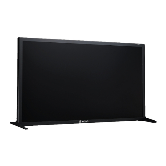
- Page 1 Bosch High Performance HD LED Monitors UML-273-90 | UML-323-90 | UML-423-90 | UML-553-90 Installation Manual...
-
Page 3: Table Of Contents
Connecting an Alarm Trigger Single / Multiple Monitor Configuration Accessory Installation 5.9.1 Placing the Monitor on a Desktop 5.9.2 Mounting the Monitor to a Wall Navigating the Monitor Navigating the Control Panel Bosch Security Systems, Inc. Installation Manual 2013.02 | 3.0 |... - Page 4 Using the Monitor On-screen Display (OSD) On-screen Display Menus Picture Menu Sound Menu Option Menu 6.6.1 PIP Availability Setting Menu Power Management Power Consumption LED Indicator Troubleshooting Maintenance Technical Specifications 2013.02 | 3.0 | Installation Manual Bosch Security Systems, Inc.
-
Page 5: Safety
Never spill liquid of any kind on the unit. Do not place objects filled with liquids, such as vases or cups, on the unit. Bosch Security Systems, Inc. Installation Manual 2013.02 | 3.0 |... - Page 6 EN60950. Substitutions may damage the unit or cause fire or shock. – If unsure of the type of power supply to use, contact your dealer or local power company. 2013.02 | 3.0 | Installation Manual Bosch Security Systems, Inc.
- Page 7 17. Attachments, changes or modifications - Only use attachments/accessories specified by the manufacturer. Any change or modification of the equipment, not expressly approved by Bosch, could void the warranty or, in the case of an authorization agreement, authority to operate the equipment.
-
Page 8: Safety Precautions
All-pole power switch - Incorporate an all-pole power switch, with a contact separation of at least 3 mm in each pole, into the electrical installation of the building.If it is needed to open the 2013.02 | 3.0 | Installation Manual Bosch Security Systems, Inc. - Page 9 Disposal - Your Bosch product was developed and manufactured with high-quality material and components that can be recycled and reused. This symbol means that...
- Page 10 Bosch High Performance en | Safety HD LED Monitors Environmental statement - Bosch has a strong commitment towards the environment. This unit has been designed to respect the environment as much as possible. Electrostatic-sensitive device - Use proper CMOS/MOS-FET handling precautions to avoid electrostatic discharge. NOTE:...
- Page 11 System ground/Safety ground The system ground is only used to comply with safety standards or installation practices in certain countries. Bosch does not recommend connecting system ground to safety ground unless it is explicitly required. However, if the system ground and...
- Page 12 CCTV system. Video loss - Video loss is inherent to digital video recording; therefore, Bosch Security Systems cannot be held liable for any damage that results from missing video information. To minimize the risk of lost digital information, Bosch Security Systems recommends multiple, redundant recording systems, and a procedure to back up all analog and digital information.
- Page 13 L’utilisation de ce produit dans une zone résidentielle peut provoquer des interférences nuisibles. Le cas échéant, l’utilisateur devra remédier à ces interférences à ses propres frais. Bosch Security Systems, Inc. Installation Manual 2013.02 | 3.0 |...
- Page 14 UL MAKES NO REPRESENTATIONS, WARRANTIES, OR CERTIFICATIONS WHATSOEVER REGARDING THE PERFORMANCE OR RELIABILITY OF ANY SECURITY OR SIGNALING-RELATED FUNCTIONS OF THIS PRODUCT. 2013.02 | 3.0 | Installation Manual Bosch Security Systems, Inc.
- Page 15 Bosch High Performance Safety | en HD LED Monitors Copyright This manual is the intellectual property of Bosch Security Systems and is protected by copyright. All rights reserved. Trademarks All hardware and software product names used in this document are likely to be registered trademarks and must be treated accordingly.
-
Page 16: Customer Support And Service
Bosch High Performance en | Safety HD LED Monitors Customer Support and Service If this unit needs service, contact the nearest Bosch Security Systems Service Center for authorization to return and shipping instructions. Service Centers Repair Center- Telephone: 800-566-2283 Fax: 800-366-1329 E-mail: repair@us.bosch.com... - Page 17 Safety | en HD LED Monitors E-mail: customer.service@cn.bosch.com Warranty and more information For additional information and warranty queries, please contact your Bosch Security Systems representative or visit our website at www.boschsecurity.com. Bosch Security Systems, Inc. Installation Manual 2013.02 | 3.0 |...
-
Page 18: Unpacking
Verify that all the parts listed in the Parts List below are included. If any items are missing, notify your Bosch Security Systems Sales or Customer Service Representative. The original packing carton is the safest container in which to transport the unit and must be used if returning the unit for service. -
Page 19: Access And Connections
Bosch High Performance Access and Connections | en HD LED Monitors Access and Connections Front Control Panel Figure 3.1: UML-273-90/UML-323-90/UML-423-90/UML-553-90 Front Panel Ref. Button Description IR sensor and Receives the command signals from the LED Indicator remote control.Indicates the operating... -
Page 20: Rear Panels
Bosch High Performance en | Access and Connections HD LED Monitors Rear Panels UML-273-90 Figure 3.2: UML-273-90 Rear Panel 2013.02 | 3.0 | Installation Manual Bosch Security Systems, Inc. - Page 21 Bosch High Performance Access and Connections | en HD LED Monitors UML-323-90 Figure 3.3: UML-323-90 Rear Panel UML-423-90 Figure 3.4: UML-423-90 Rear Panel Bosch Security Systems, Inc. Installation Manual 2013.02 | 3.0 |...
- Page 22 Increases audio volume. Decreases the value Scrolls left in the OSD. when in the OSD. Decreases audio volume. Adjusts the value when Scrolls up in the OSD. in the OSD. 2013.02 | 3.0 | Installation Manual Bosch Security Systems, Inc.
-
Page 23: Adjustment Function
Activates the Auto Adjustment function when in PC mode. MENU Selects the on-screen display (OSD). VIDEO Selects the signal to be displayed. SOURC Serves as the “Enter” function for OSD menus. ENTER Bosch Security Systems, Inc. Installation Manual 2013.02 | 3.0 |... -
Page 24: Bottom Panel
16 AUDIO IN - AUDIO 3 update) VIDEO IN - COMPONENT 17 AC SWITCH ON/OFF VIDEO IN - S-VIDEO 18 100 - 240 VAC IN VIDEO OUT 19 100 - 240 VAC OUT VIDEO IN 2013.02 | 3.0 | Installation Manual Bosch Security Systems, Inc. -
Page 25: Remote Control
15 Exit Exits the OSD menu. 16 (no function) 17 Arrow Moves the cursor down, up, left, and Keys right in the OSD. Accepts a selection in Enter an OSD menu. Bosch Security Systems, Inc. Installation Manual 2013.02 | 3.0 |... -
Page 26: Remote Control Battery Installation
(+) and (-) marks inside the battery case. Slide the battery cover back into place. Figure 3.7: Remote Control Battery Replacement Note: Replace batteries when required or at least once a year. Dispose of used batteries properly. 2013.02 | 3.0 | Installation Manual Bosch Security Systems, Inc. -
Page 27: Description
Description | en HD LED Monitors Description The Bosch High Performance Family of LCD monitors display PAL or NTSC standard color pictures in CCTV systems. One (1) looping Composite Video BNC connector input, one Component Video BNC connector input, three (3) Audio input RCA, and one (1) Y/C (S-Video) input using a 4-pin mini-DIN are included. -
Page 28: Power
100 to 240 < 75 W NTSC/PA 50/60 Hz UML-423- 120/230 100 to 240 < 150 W NTSC/PA 50/60 Hz UML-553- 120/230 100 to 240 < 170 W NTSC/PA 50/60 Hz 2013.02 | 3.0 | Installation Manual Bosch Security Systems, Inc. -
Page 29: Installing The Monitor
Connecting Power The Bosch Flat Panel CCTV monitors are delivered with a 3-pole US-style power cord and a 3-pole Euro-style power cord. Use the US-style power cord where 120 VAC, 60 Hz power is available;... -
Page 30: Connecting The Y/C (S-Video) Signal To The Monitor
There are three ways to connect the PC signal to the monitor: HDMI, DVI, and VGA. 5.6.1 HDMI Connection The monitor can be connected to the HDMI (High Definition Multimedia Input) by connecting a HDMI cable (not supplied). 2013.02 | 3.0 | Installation Manual Bosch Security Systems, Inc. -
Page 31: Dvi Connection
11 Ground Green Green Ground 12 SDA (for DDC) Video Blue Video Blue Ground 13 H-Sync or H+V Sync Ground 14 V-Sync Ground 10 Signal Cable 15 SCL (for DDC) Detect Bosch Security Systems, Inc. Installation Manual 2013.02 | 3.0 |... -
Page 32: Connecting An Alarm Trigger
The cable is routed to the back panel of the UML monitor and the plug-end of the wire is connected to the Trigger Input port. Refer to Setting Menu, page 53, for configuring alarm acknowledgement. 2013.02 | 3.0 | Installation Manual Bosch Security Systems, Inc. - Page 33 Press the Down arrow button until Trigger is highlighted; then press the Right arrow button. Make the necessary changes to the Trigger menu so that the settings match the following: Bosch Security Systems, Inc. Installation Manual 2013.02 | 3.0 |...
- Page 34 Bosch High Performance en | Installing the Monitor HD LED Monitors Picture Trigger Enable Trigger Input Buzzer Trigger Time Trigger Option High :Move :Enter :Exit 2013.02 | 3.0 | Installation Manual Bosch Security Systems, Inc.
-
Page 35: Single / Multiple Monitor Configuration
Bosch High Performance Installing the Monitor | en HD LED Monitors Single / Multiple Monitor Configuration Figure 5.6: Single Monitor Configuration Description Description Video Camera Video Out Video In Bosch Security Systems, Inc. Installation Manual 2013.02 | 3.0 |... -
Page 36: Accessory Installation
The monitors can be placed on a desktop or mounted to a wall using mounting accessories that are sold separately. Refer to the Bosch Security Systems, Inc. Web site or contact your local customer support representative for more information. 2013.02 | 3.0 | Installation Manual Bosch Security Systems, Inc. -
Page 37: Placing The Monitor On A Desktop
5.9.1 Placing the Monitor on a Desktop The following illustrations show how to install the optional stands onto the rear panel of the monitor for a desktop application. UML-273-90 UML-323-90 Bosch Security Systems, Inc. Installation Manual 2013.02 | 3.0 |... -
Page 38: Mounting The Monitor To A Wall
The monitor may be mounted to a wall using the mounting holes and a suitable wall mount or swivel/tilt mount. Use a UL-Listed mounting device. Ensure that the mount is strong enough to bear the weight of the monitor, as follows: 2013.02 | 3.0 | Installation Manual Bosch Security Systems, Inc. - Page 39 Refer to the figures below for the dimensions of the mounting holes. 200 mm 100 mm Figure 5.8: UML-273-90 - Location of mounting holes 200 mm 200 mm Figure 5.9: UML-323-90 - Location of mounting holes Bosch Security Systems, Inc.
- Page 40 | Installing the Monitor HD LED Monitors 400 mm 400 mm Figure 5.10: UML-423-90 - Location of mounting holes 400 mm 400 mm Figure 5.11: UML-553-90 - Location of mounting holes 2013.02 | 3.0 | Installation Manual Bosch Security Systems, Inc.
-
Page 41: Navigating The Monitor
HD LED Monitors Navigating the Monitor Navigating the Control Panel Use the control panel to make any necessary OSD adjustments. See the figure below for an explanation of the control panel. Bosch Security Systems, Inc. Installation Manual 2013.02 | 3.0 |... - Page 42 Adjusts the value when Scrolls up in the in the OSD. OSD. Adjusts the value when Scrolls down in in the OSD. the OSD. Auto adjusts when in PC mode. 2013.02 | 3.0 | Installation Manual Bosch Security Systems, Inc.
-
Page 43: Using The Monitor On-Screen Display (Osd)
Press the Menu button to exit the selected menu and to return to the menu bar or to confirm a selection. 10. Press the Menu button again to exit the OSD menu bar. Bosch Security Systems, Inc. Installation Manual 2013.02 | 3.0 |... -
Page 44: On-Screen Display Menus
Detection settings. Setti Resets the factory default settings and adjusts the overall monitor settings. Note: Some of the OSD menu functions may not be available according to the input source detected. 2013.02 | 3.0 | Installation Manual Bosch Security Systems, Inc. -
Page 45: Picture Menu
Menu button again to exit the OSD. Picture PIcture Mode Standard Contrast Brightness Color Tint Sharpness Backlight Color Temp 9300°K Input Resolution Blue Screen :Move :Enter :Exit Bosch Security Systems, Inc. Installation Manual 2013.02 | 3.0 |... - Page 46 Color Selects the color temperature. Choices are: Temp – 12000°K, 9300°K, and 6500°K . – Options under User: Red, Green, and Blue (range 0-255). 2013.02 | 3.0 | Installation Manual Bosch Security Systems, Inc.
- Page 47 Enables or disables video loss indication. Choices Screen are: – ON: displays a blue background when video loss is detected. – OFF: displays a black background when video loss is detected. Bosch Security Systems, Inc. Installation Manual 2013.02 | 3.0 |...
-
Page 48: Sound Menu
Menu button again to exit the OSD. Sound Volume Mute Audio Source Audio 2 Speaker External :Move :Enter :Exit Submen Definition Volume Controls the built-in speaker volume (range 0-100). 2013.02 | 3.0 | Installation Manual Bosch Security Systems, Inc. - Page 49 (audio signal from the HDMI connector). Speaker Sets the monitor to play audio using the external speakers, external audio devices (if connected), or built-in (internal) speaker. Choices are: External, Line-Out, and Internal. Bosch Security Systems, Inc. Installation Manual 2013.02 | 3.0 |...
-
Page 50: Option Menu
External Clock Frequency Phase H Position V Position Ambient Light Sensor Auto Detection :Move :Enter :Exit Submenu Definition Aspect Ration Selects the Aspect Ratio mode. Choices are: Full and Original. 2013.02 | 3.0 | Installation Manual Bosch Security Systems, Inc. - Page 51 Choices are: High, Low, and OFF. Auto Allows the monitor to automatically switch to Detection and display an available input signal. Bosch Security Systems, Inc. Installation Manual 2013.02 | 3.0 |...
-
Page 52: Pip Availability
PIP feature. (A “+” indicates an allowed combination, a blank cell indicates the combination is not allowed). Main Picture Input Source Comp HDMI Video Pictu S-Video Comp. HDMI 2013.02 | 3.0 | Installation Manual Bosch Security Systems, Inc. -
Page 53: Setting Menu
Menu button again to exit the OSD. Setting Language English Overscan Key Lock Trigger Schedule Display Wall Power Save Set Monitor ID Image Retention Auto Adjustment Advanced :Move :Enter :Exit Bosch Security Systems, Inc. Installation Manual 2013.02 | 3.0 |... - Page 54 – Trigger Option: sets the trigger signal type: N/C (normal closed), N/O (normal opened), High (2~5V) or Low (0~0.6V). 2013.02 | 3.0 | Installation Manual Bosch Security Systems, Inc.
- Page 55 For example, if schedule item #1 sets the monitor to power on at 10:00 AM and off at 5:00 PM, and schedule item #2 sets Bosch Security Systems, Inc. Installation Manual 2013.02 | 3.0 |...
- Page 56 Frame Comp.: turns frame compensation on or off. If turned on, the monitor adjusts the image to compensate for the width of the bezels in order to accurately display the image. 2013.02 | 3.0 | Installation Manual Bosch Security Systems, Inc.
- Page 57 Image If turned on, the LCD monitor automatically Retention displays swift moving patterns to prevent the formation of image retention on the screen. Bosch Security Systems, Inc. Installation Manual 2013.02 | 3.0 |...
- Page 58 To disable the Key Lock feature using the front panel buttons, press and hold both the INPUT (or ENTER) and the MENU buttons until the monitor displays the Key Unlocked message. 2013.02 | 3.0 | Installation Manual Bosch Security Systems, Inc.
-
Page 59: Power Management
The power management feature of the monitor is comprised of these stages: Mode Monitor Operation Color Green Normal Operation UNSUPPORTE Green Normal operation but the screen D MODE displays an error message. POWER OFF Not Operational Bosch Security Systems, Inc. Installation Manual 2013.02 | 3.0 |... -
Page 60: Troubleshooting
Push the down arrow key to activate the horizontal noise Auto Adjust function. is present in the - or - picture Adjust the Frequency and Phase in the PC OSD submenu. 2013.02 | 3.0 | Installation Manual Bosch Security Systems, Inc. - Page 61 – 1280 x 768 (60Hz) – 1280 x 960 (60Hz) – 1280 x 1024 (60Hz) – 1366 x 768 (60Hz) – 1600 x 1200 (60Hz) – 1920 x 1080 (60Hz) Bosch Security Systems, Inc. Installation Manual 2013.02 | 3.0 |...
-
Page 62: Maintenance
Ketone type materials – Ethyl alcohol – Ethyl acid – Toluene – Methyl chloride – Ammonia Use of these materials may permanently damage the polarizer due to a chemical reaction. 2013.02 | 3.0 | Installation Manual Bosch Security Systems, Inc. -
Page 63: Technical Specifications
S-Video (Mini Din 4-pin 1ch input (Y/C)) Component (YPbPr, RCA) HDMI DVI-D PC RGB (D-Sub connector) Audio In (L/R) x 2 Line In (3.5 mm) Trigger In RS-232 (D-Sub 9 pin) Bosch Security Systems, Inc. Installation Manual 2013.02 | 3.0 |... - Page 64 9.05 kg (with stand) 12.5 kg (27.6 lb) (19.95 lb) Gross Weight 12.35 kg 15.1 kg (33.3 lb) (27.23 lb) Electric Ratings 120/230 VAC, 50/60 Hz 120/230 VAC, 50/60 Hz 2013.02 | 3.0 | Installation Manual Bosch Security Systems, Inc.
- Page 65 RS-232 (D-Sub 9 pin) Output Signal Video (BNC 1ch input 1.0 Vp-p, 75 Ohm terminated, loop-through out) Audio Out (L/R) External Speaker PC RGB (D-Sub Connector) RS-232 (D-Sub 9 pin) Bosch Security Systems, Inc. Installation Manual 2013.02 | 3.0 |...
- Page 66 (W x H x D) Net Weight 20 kg (44.1 lbs) 32 kg (70.5 lbs) Gross Weight 26 kg (57.3lbs) 37 kg (81.6 lbs) Electric Ratings 120/230 VAC, 50/60 Hz 120/230 VAC, 50/60 Hz 2013.02 | 3.0 | Installation Manual Bosch Security Systems, Inc.
- Page 68 Bosch Security Systems, Inc. 850 Greenfield Road Lancaster, PA, 17601 www.boschsecurity.com © Bosch Security Systems, Inc., 2013...