Table of Contents
Advertisement
Quick Links
Advertisement
Table of Contents
Troubleshooting

Related Manuals for Bosch DDU 8


Summary of Contents for Bosch DDU 8
- Page 1 Display DDU 8 Manual V1.2 9/16/2016...
-
Page 2: Table Of Contents
10.6 Configuring PWM outputs ................................ 87 11 Online Measurement ............................91 11.1 Achieving an online connection .............................. 91 11.2 Setting up an online measurement ............................92 11.3 Online calibration of measurement channels ........................97 2 / 160 DDU 8 Manual Bosch Motorsport... - Page 3 18.1 Setting up fuel consumption calculation and tank management ................149 18.2 Fuel consumption diagnosis/counter reset ........................150 18.3 Example ......................................151 19 Enhancements ..............................152 19.1 Modular sensor interface M 60 ............................. 152 20 RaceCon Shortcuts ............................157 Bosch Motorsport DDU 8 Manual 3 / 160...
-
Page 4: Preparation
1 | Preparation Preparation Use the DDU 8 only as intended in this manual. Any maintenance or repair must be performed by authorized and qualified personnel approved by Bosch Motor‐ sport. Operation of the DDU 8 is only certified with the combinations and accessories that are specified in this manual. -
Page 5: Power Supply
Power Supply | 2 Power Supply Bosch Motorsport software is developed for Windows system software. Connect the Ethernet line to your computer and install the driver. Read the manual care‐ fully and follow the application hints step by step. Please ensure that you have a good ground installation. That means: ▪... -
Page 6: Onboard Network Concept
3 | Onboard Network Concept Onboard Network Concept 6 / 160 DDU 8 Manual Bosch Motorsport... -
Page 7: Technical Data
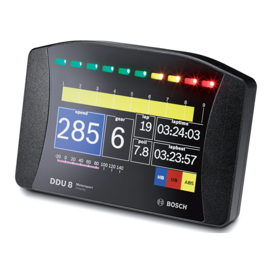
BT 60 burst telemetry system. As a base system the DDU 8 is sold as display only. Software upgrades for the DDU 8 (field upgradable by entering a key) activate data logger functionality, ad‐... - Page 8 B 261 209 659‐01 ment or page selection, 6 steps Software Upgrade 1 F 02U V00 701‐01 Activation of internal data logger 2 GB Telemetry support BT 60 Long range telemetry support FM 40 8 / 160 DDU 8 Manual Bosch Motorsport...
-
Page 9: Installation Notes
Software Upgrade 4 F 02U V00 871‐02 USB‐Port unlocked (Rugged USB flash drive 2 GB Bosch File System (BFS) for‐ mat included, works with Bosch File System (BFS) preformatted USB Flash drive only) Adapter cable to USB‐Port (included) F 02U V01 343‐01... -
Page 10: Inputs And Outputs
Inputs and Outputs Input channels Analog inputs The DDU 8 analog inputs accept an input signal of 0 to 5 V. A 3.01 kOhm pull‐up resistor can be activated by software. Digital inputs The digital inputs of the DDU 8 accept 0 V to 5 V signals of Hall‐effect sensors by default. -
Page 11: Output Channels
PWM outputs. Sensor power supply The DDU 8 has 3 types of sensor power supply: 12 V unregulated battery voltage, 5 V and 10 V regulated voltage. The 12 V unregulated output is fused and rated 1 A max. -
Page 12: Pin Layout Life Connector
'cable auto crossover' functionality. RS232 ports The DDU 8 has two RS232 serial ports. Baudrate for both ports is programmable. RS232 port 1 is reserved for online telemetry, port 2 can be used for reception of data from a serial GPS receiver. - Page 13 LS_SWITCH_4 PWM lowside switch 4 input LS_GND_2 PWM ground output ANA01: Page select analog signal 1 input 337 ANA02: Brightness se‐ analog signal 2 input lect ANA03 analog signal 3 input Bosch Motorsport DDU 8 Manual 13 / 160...
-
Page 14: Pin Layout Sensor Connector
3 negative (ind.) REV4_P speed signal 4 positive (ind. and input hall) REV4_M speed signal 4 negative (ind.) ANA07 analog signal 7 input ANA08 analog signal 8 input ANA09 analog signal 9 input 14 / 160 DDU 8 Manual Bosch Motorsport... - Page 15 21 input ANA22 analog signal 22 input ANA23 analog signal 23 input ANA24 analog signal 24 input ANA25 analog signal 25 input ANA26 analog signal 26 input LAP_TRIG laptrigger input input Bosch Motorsport DDU 8 Manual 15 / 160...
-
Page 16: Mechanical Drawing
6 | Mechanical Drawing Mechanical Drawing 16 / 160 DDU 8 Manual Bosch Motorsport... -
Page 17: Starting Up
Click ‘OK’ Click when done ‘Properties’ 7.1.2 Starting the Unit The DDU 8 powers up by turning on the ignition of the car. At startup the DDU 8 will display a Bosch logo. Bosch Motorsport DDU 8 Manual 17 / 160... - Page 18 About RaceCon RaceCon is an all integrated software tool for configuration and calibration of Bosch Motorsport hardware products. It is used to set up, configure and calibrate the DDU 8. For better understanding, Bosch Motorsport offers a video tutorial that explains many functions of RaceCon.
- Page 19 Starting up | 7 All (sub‐) windows are resizable and dockable. 1. Start the RaceCon software. Bosch Motorsport DDU 8 Manual 19 / 160...
- Page 20 7 | Starting up 2. In the ‘File’ menu select ‘New’ to create a new project. 3. In the Toolbox select the DDU 8 and drag it into the Main Area. A pop up window to specify the DDU 8 program archive appears.
- Page 21 6. Choose the way to switch display pages that fits to your hardware configura‐ tion. 7. Click ‘Finish’. The DDU 8 is inserted into the project and RaceCon tries to connect to the device. RaceCon detects configuration differences between the DDU 8 and the Race‐...
- Page 22 7 | Starting up 8. Click ‘OK’ to proceed. Successful Ethernet connection, DDU ‘talks’ to PC The download starts and the DDU 8 carries out a reset. 22 / 160 DDU 8 Manual Bosch Motorsport...
-
Page 23: Feature Activation
Starting up | 7 After the reset RaceCon reconnects to the DDU 8. Local configuration on both the PC and DDU 8 match (Indicated by green background and dot). The DDU 8 is now connected to RaceCon. Green back- ground and... - Page 24 7 | Starting up 1. To activate a feature, double‐click on ‘DDU 8’ in the Project Tree and click on the ‘Features info’ tab in the Main Area. : Double- click on ‘DDU 8’ : Click on ‘Features Info’ The ‘DDU 8 features info’ window appears.
-
Page 25: First Display Configuration (Quick Start)
‘OK’ when done. The feature’s status changes to ‘unlocked’. 4. Perform these steps to activate other features you purchased. 5. Switch the car’s ignition off and on again to cycle the power of DDU 8. First display configuration (Quick start) This chapter explains the configuration of a display element showing the battery voltage. - Page 26 ‘Large Element’ box shows that it is not linked to a measure‐ ment channel. 4. In the DDU 8 Project Tree, click on ‘DDU 8’ to display the available measure‐ ment channels. 5. In the data window, scroll down to ‘ub’ (measurement channel for battery voltage).
- Page 27 Starting up | 7 6. Drag the ‘ub’ measurement channel from the Data Area and drop it on the ‘Large Element’. 7. Right‐click on ‘DDU 8’ in the DDU 8 Project Tree and choose ‘Download Con‐ figuration’. Click ‘Download configuration’...
-
Page 28: First Recording (Quick Start)
See chapter ‘Recording and Telemetry’ for a detailed instruction to con‐ figure recordings. This function requires the installation of Software Upgrade 1. For data recording on the DDU 8, the software upgrade ‘DDU 8 Datalogger’ must be activated. See chapter ‘Feature activation 23]’ for an instruction to activate software up‐... - Page 29 : Click ‘+’ : Click ‘Logger’ : Double-click ‘Recording’ 5. In DDU 8 Project Tree, click on ‘DDU 8’ to display the available measurement channels. In the data window, scroll down to ‘ub’ (measurement channel for battery voltage). Click ‘DDU 8‘...
- Page 30 7 | Starting up 7. Right‐click on ‘DDU 8’ in the DDU 8 Project Tree and choose ‘Download con‐ figuration’. Click ‘Download configuration’ The configuration download starts and the DDU 8 carries out a reset. As we did not define global start conditions, recording starts immediately.
- Page 31 12. Click on ‘Modify’ button and select the base folder. 13. Choose ‘FTP’ as data transmission method. 14. Choose ‘XXXXXXXXXXX’ in the Vehicle dropdown list. 15. Activate ‘Auto save’. 16. Click ‘Save’ when done. Choose ‚DDU8‘ in Dropdown List Bosch Motorsport DDU 8 Manual 31 / 160...
- Page 32 7 | Starting up 17. Connect the DDU 8 network cable. Data transmission from the DDU 8 starts automatically. Measurement files are stored automatically in the base folder. 18. Click on ‘Close’ when transmission has finished. 19. Click on the Start button and choose ‘Open measurement file’.
-
Page 33: Set Time & Date
8, ‘Date & Time’ can be programmed by RaceCon. We recommend min. 5 hours charge time. Please connect the DDU 8 to the PC and click on ‘Set Date & Time’ in the Context menu of the DDU 8. Bosch Motorsport... -
Page 34: Display Configuration
8 | Display Configuration Display Configuration ▪ DDU 8 DDU 8 features: 800 x 480 full color TFT display + 10 color LEDs ▪ Display and LEDs are fully configurable ▪ ECU channels, analog channels, and CAN channels can be displayed ▪... -
Page 35: Display Element Configuration
8.1.3 Selecting display pages Click on ‘DDU 8’ in the DDU 8 Project Tree, then on ‘Display’ and double‐click on the page you want to select (example: ‘New Page’). In the Main Area, a representation of the DDU 8 opens. - Page 36 Drag + Drop 2. Drag a measurement channel from the Data Area and drop it on the numeric display element. The measurement channel is linked to the numeric display element. Drag + Drop 36 / 160 DDU 8 Manual Bosch Motorsport...
- Page 37 Drag the ‘Bargraph’ display element from the Toolbox and drop it on the display page. Configuring a ‘Bargraph’ display element 1. Double‐click on the ‘Bargraph’ display element. The Bargraph Wizard window opens. Bosch Motorsport DDU 8 Manual 37 / 160...
- Page 38 ▪ Alarm Icon: An alarm displaying a defined image (e.g. a warning triangle) Adding an ‘Alarm’ display element to display page Drag an ‘Alarm’ element from the Toolbox and drop it on the display page. 38 / 160 DDU 8 Manual Bosch Motorsport...
- Page 39 Enter the time until the Alarm can appear again after a reset. 3. Click ‘OK’ when done. 4. Copy alarm to all display pages by clicking ‘Move to’ ‐> ‘All Pages’. Bosch Motorsport DDU 8 Manual 39 / 160...
- Page 40 2. Switch to the tab ‘Alarm representation’. It is configured in the same way as the ‘Alarm’ text display element. 3. Click ‘OK’ when done. If several active alarms in the display overlap, each alarm is in Notice the foreground for 2 seconds. 40 / 160 DDU 8 Manual Bosch Motorsport...
- Page 41 Drag the Label or picture display element from the Toolbox and drop it on the display page. Configuring a Label display element 1. Double‐click on the Label display element. The Label Wizard window opens. Bosch Motorsport DDU 8 Manual 41 / 160...
- Page 42 Example: The text color changes from white to red when the battery voltage is fewer than 12 V. Conditional Formatting is available at numeric, ‘Bargraph’ and ‘Alarm’ display ele‐ ment. 42 / 160 DDU 8 Manual Bosch Motorsport...
-
Page 43: Leds
‘true’. 8.3.1 Configuring shift LEDs To use shift LEDs, RPM and gear measurement channels an ECU has to be loaded in RaceCon. 1. Click on the tab ‘LEDs’ in the display view. Bosch Motorsport DDU 8 Manual 43 / 160... - Page 44 Choose the measurement channel for ‘Gear’. Gear must have an ASCII quantization (1st gear=‘1’= 49, 2nd gear=‘2’= 50, …). (ASCII quantization is standard for the ‘gear’ channel of Bosch ECUs. If you get the gear information of a different control unit as the Bosch ECU (e.g. a gearbox control unit), use the Gear Lookup Table to translate numeric values to ASCII format.
- Page 45 Gear Lookup Table Wizard 1. Set up the settings as shown in the screenshot. 2. Click ‘OK’ when done. The ‘Create channel on DDU 8’ window appears. Enter the name and an optional description of the translated ASCII measure‐ ment channel.
- Page 46 ‘Display “on” pattern’ and define the LEDs in the one color. Then choose ‘Display “off” pattern’ and define the LEDs in the other color. 2. Click ‘OK’ when done. 3. The configuration is displayed in the DDU 8 LED Configuration window. 8.3.4 Assigning display pattern priority Assigning display pattern priority You can assign the priority of the created display pattern and shift lights.
-
Page 47: Page Select
Option 1: 12 position switch ▪ 12 position switch connected to analog input ANA01 ▪ 3 kOhm pull‐up resistor in DDU 8 automatically activated ▪ 12 position switch connects resistor to GND (43,9 / 142 / 264 / 409 / 609 /... - Page 48 8 | Display Configuration Connection diagram of 12 position switch If pin ANA01 is open or directly connected to GND, the DDU 8 Notice displays Page 1 by default. 8.4.2 Option 2: Up/down switches ▪ ‘Up switch’ connects ANA01 to GND ▪...
-
Page 49: Display And Led Brightness
Display and LED brightness ▪ 6 position switch connected to analog input ANA02 ▪ 3 kOhm pull‐up resistor in DDU 8 automatically activated ▪ 6 position switch connects resistor to GND (43,9 / 142 / 264 / 409 / 609 / 846... - Page 50 ▪ Result can be used as input source for various display elements (numeric ele‐ ments, alarms, Bargraphs) and further calculations in the whole RaceCon project All math channels can be used globally in the whole DDU 8 project. 8.6.2 Creating a new math channel 1.
- Page 51 Define a value that can be used as a constant in the formula. g) Choose a function. h) Describes the function selected above. 2. Click ‘Finish’ when done. The math channel is displayed in the DDU 8 math channel window. 8.6.3 Creating a new conditional function 1.
- Page 52 ▪ when If‐condition changes state from FALSE to TRUE. An example of a condition to set up the maximum front brake pressure is given on the next page. The conditional function is displayed in the DDU 8 math channel window. 52 / 160 DDU 8 Manual...
-
Page 53: Condition Channels
▪ Logical operations on measurement channel(s) ▪ If‐Else structure with reset ▪ Logical result ▪ Result can be used as input source for Alarm display elements and further calculations in the whole RaceCon project. Bosch Motorsport DDU 8 Manual 53 / 160... - Page 54 ▪ Combination of several (up to 16) condition channels for more complex cal‐ culations ▪ Logical results All conditions can be used globally in the whole DDU 8 project. 8.7.1 Creating a new condition channel 1. Follow the steps shown in the screenshot.
- Page 55 Pulse: Result is a short one-time pulse if the condition is fulfilled. Toggling output: Result is a pulse that lasts until the next condition is fulfilled. 2. Click ‘Ok’ when done. The conditional channel is displayed in the DDU 8 condition channel window. 8.7.2 Creating a new condition combination 1.
-
Page 56: Cpu Load Limits
100 %. Bosch recommends a maximum CPU load of 85 % (averaged). Exceeding this lim‐ it might result in DDU 8 not being able to fulfill its required measuring/logging/ display tasks or even in the DDU 8 crashing and rebooting. - Page 57 ▪ Logger configuration (total logging rate [kB/s], conditional measurement rates) To help respecting the limit of 85 % CPU load, the DDU 8 creates an error memo‐ ry entry. To trigger this error entry, the CPU load must exceed the limit for 5 mi‐...
-
Page 58: Can Bus
DDU 8 has two fully configurable CAN buses. ▪ Baudrate (125 kBit to 1 MBit) ▪ 11 Bit or 29 Bit identifiers ▪ Input configuration: Read messages from CAN bus and convert to DDU 8 measurement/display variables. CAN bus supports row counter configura‐ tion. -
Page 59: Can Input
2. Select ‘New CAN Channel’ from menu. 3. Insert name and description of channel. 4. Click ‘OK’ when done. The channel is listed in the Data window and a CAN channel configuration win‐ dow opens. Bosch Motorsport DDU 8 Manual 59 / 160... - Page 60 • Orange colored fields show the assignment of the multiplexer bytes. Representation: Bit Some CAN devices need to be addressed by a bit represented CAN channel. The address can be assigned in this window and is illustrated by a matrix table. 60 / 160 DDU 8 Manual Bosch Motorsport...
-
Page 61: Special Features
This functionality is only available, if a MSA‐Box (I & II) is used to connect the DDU 8 to the PC. Choose the CAN bus that is connected to the MSA‐Box to dis‐ play the raw value and the converted physical value here. - Page 62 9 | CAN Bus For an online view of the value measured by the DDU 8 , insert the channel in an online measurement sheet which is described in the next chapter. 9.2.7 Online view of CAN channels in vehicle 1.
- Page 63 The channels are inserted in the Data window. 9.2.9 Export RaceCon CAN configuration 1. Right‐click on CAN Input of desired bus (CAN1 or CAN2). 2. Select ‘Export…’ from menu. An ‘Export Selection’ window opens. Bosch Motorsport DDU 8 Manual 63 / 160...
- Page 64 5. Drag and drop the channel to ‘CAN Input’ of desired CAN bus on right hand side. 6. Click ‘Next’. If a measurement channel belongs to more than one source (e.g. C 60 and ECU MS 5.1), the ‘Solve Label Ambiguity’ window opens. 64 / 160 DDU 8 Manual Bosch Motorsport...
-
Page 65: Can Output
9.3.2 Create new CAN output message channel 1. Right‐click on CAN Output of desired bus (CAN1 or CAN2). 2. Select ‘New CAN Message’ from menu. The ‘Create new CAN message’ window opens. Bosch Motorsport DDU 8 Manual 65 / 160... - Page 66 5. Click ‘OK’ when done. A CAN message configuration window opens in the Main Area. 6. Click on ‘DDU 8’ in the DDU 8 Project Tree to display all labels. 7. Select the desired measurement channel and drop it on message’s bytes.
- Page 67 ▪ Representation: Also a Bitwise CAN signal can be defined. Please define posi‐ tion and length in this case. ▪ Quantization: Physical values can be calculated by entering Factor/Offset. Signed and unsigned is optional. Bosch Motorsport DDU 8 Manual 67 / 160...
- Page 68 Endianness: Define Byte order (Little Endian –LB, HB, Big Endian –HB, LB) 9.3.4 Export RaceCon CAN configuration 1. Right‐click on CAN Output of desired bus (CAN1 or CAN2). 2. Select ‘Export…’ from menu. The ‘Export Selection’ window opens. 3. Specify the filename. 68 / 160 DDU 8 Manual Bosch Motorsport...
- Page 69 5. Drag and drop the channel to ‘CAN Output’ of desired CAN bus on right hand side. 6. Click ‘Next’. If a measurement channel belongs to more than one source (e.g. C 60 and ECU MS 5.1), the ‘Solve Label Ambiguity’ window opens. Bosch Motorsport DDU 8 Manual 69 / 160...
- Page 70 9 | CAN Bus 7. Assign the ambiguous channels to the desired source. 8. Click ‘Finish’. 70 / 160 DDU 8 Manual Bosch Motorsport...
-
Page 71: Analog And Frequency Inputs
Filtered channels are routed through digital low pass filters: ▪ DDU 8 uses A/D converter oversampling and digital filtering to recording rate Bosch Motorsport DDU 8 Manual 71 / 160... -
Page 72: Configuring Inputs
1. Click on ‘Measurement Sources’ in the Toolbox. 2. Expand the list of ‘I/O Channels’ by clicking on ‘+’ in the DDU 8 Project Tree. 3. Drag the ‘Bosch Sensor Wizard’ from the Toolbox and drop it on the desired analog input channel in the DDU 8 Project Tree. - Page 73 The sensor has a linear output signal with sensitivity and offset 1. Click on ‘Measurement Sources’ in the Toolbox. 2. Expand the list of ‘I/O Channels’ by clicking on ‘+’ in the DDU 8 Project Tree. Bosch Motorsport DDU 8 Manual...
- Page 74 10 | Analog and Frequency Inputs 3. Drag the ‘Sensitivity/Offset’ analog signal source from the Toolbox and drop it on the desired analog input channel in the DDU 8 Project Tree. A ‘Sensitivi‐ ty/Offset Wizard’ opens. 4. To activate the internal pullup‐resistor, check the box.
- Page 75 ‘Setting up an online measurement 92]’. 7. Click ‘Finish’ when done. 8. Enter channel name and description. 9. Click ‘OK’ when done. The channel is inserted into the DDU 8 Project Tree. Channel is linked to ANA04 Sensitivity...
- Page 76 Thermistor 1. Click ‘Measurement Sources’ in the Toolbox. 2. Expand the list of ‘I/O Channels’ by clicking on ‘+’ in the DDU 8 Project Tree. 3. Drag the ‘Characteristic Curve’ analogue signal source from the Toolbox and drop it on the desired analogue input channel in the DDU 8 Project Tree. A ‘Characteristic Curve Wizard’...
- Page 77 ‘Setting up an online measurement 92]’. 7. Click ‘Finish’ when done. 8. Enter channel name and description. 9. Click ‘OK’ when done. The channel is inserted into the DDU 8 Project Tree. Channel is linked to ANA05 Input pin...
- Page 78 Force at wheel 1. Click on ‘Measurement Sources’ in the Toolbox. 2. Expand the list of ‘I/O Channels’ by clicking on ‘+’ in the DDU 8 Project Tree. 3. Drag the ‘Multipoint Adjustment’ analog signal source from the Toolbox and drop it on the desired analog input channel in the DDU 8 Project Tree.
- Page 79 ‘Setting up an online measurement 92]’. 8. Click ‘Finish’ when done. 9. Enter channel name and description. 10. Click ‘OK’ when done. The channel is inserted into the DDU 8 Project Tree. Bosch Motorsport DDU 8 Manual 79 / 160...
- Page 80 Online definition of the curve is covered in the chapter ‘Online calibration of measurement channels 97]’ of this manual. 10.3.5 Digital filter details DDU 8 uses A/D converter oversampling and digital filtering to recording rate. Digital filters eliminate ‘out‐of‐band’ noise 80 / 160 DDU 8 Manual Bosch Motorsport...
- Page 81 ▪ Filtering is (smart) averaging over several samples ▪ Filtered signal is delayed with respect to real time signal ▪ DDU 8 filters have constant, frequency independent delay ▪ Delay (e.g. 22 samples at 10 ms) is corrected during recording ▪...
- Page 82 10 | Analog and Frequency Inputs 1. Click ‘Measurement Sources’ in the Toolbox. 2. Expand the list of ‘I/O Channels’ by clicking on ‘+’ in the DDU 8 Project Tree. 3. Drag the ‘Velocity’ digital signal source from the Toolbox and drop it on the desired ‘REV’...
-
Page 83: Computed Sources
Example: Sensitivity/offset calculation on input channel 1. Click ‘Measurement Sources’ in the Toolbox. 2. Drag the ‘Sensitivity/Offset’ computed source from the Toolbox and drop it on ‘Computed Channels’ in the DDU 8 Project Tree. A ‘Computed Sensitivity/Offset Wizard’ opens. Choose input... -
Page 84: Hysteresis
‘Setting up an online measurement 92]’. 5. Click ‘Finish’ when done. 6. Enter channel name and description. 7. Click ‘OK’ when done. The channel is inserted into the DDU 8 Project Tree. 10.5 Hysteresis The hysteresis function avoids the high‐frequent switchover of the measurement channel value. - Page 85 Enter name to automatically create a new measurement sheet 5. Click ‘Finish’ when done. 6. Enter channel name and description. 7. Click ‘OK’ when done. The channel is inserted into the DDU 8 Project Tree. Bosch Motorsport DDU 8 Manual 85 / 160...
- Page 86 2. Click on ‘Measurement Sources’ in the Toolbox. 3. Drag the ‘Speed’ computed source from the Toolbox and drop it on ‘Compu‐ ted Channels’ in the DDU 8 Project Tree. Do not drop it on ‘DDU 8’! 86 / 160...
-
Page 87: Configuring Pwm Outputs
Choose driven axle Choose individual wheel speed channels Set limit for speed difference for calculation 4. Click ‘Finish’ when done. The speed calculation is inserted into the DDU 8 Project Tree. Speed calculation in DDU 8 Project Tree Measurement channels... - Page 88 1. Click on ‘Measurement Sources’ in the Toolbox. 2. Drag the ‘PWM Out’ computed source from the Toolbox and drop it on the desired ‘PWM_OUT’ channel in the DDU 8 Project Tree. 3. A ‘PWM Out Wizard’ opens. 88 / 160...
- Page 89 The ‘power-on’ state of the PWM output is ‘switch open’ (0% Notice duty cycle). 4. Click ‘Finish’ when done. 5. Enter channel name and description. 6. Click ‘OK’ when done. The channel is inserted into the DDU 8 Project Tree. Channel is linked to Characteristic Output PWM_OUT02...
- Page 90 10 | Analog and Frequency Inputs Measurement label Function pwm_err_ls_out_01_SCG PWM output 1 error short circuit to GND Tab. 1: Diagnostic channels The diagnosis of PWM output 2-4 is similar. Notice 90 / 160 DDU 8 Manual Bosch Motorsport...
-
Page 91: Online Measurement
▪ System configuration (channel + display configuration, CAN I/O, PWM Out, etc.) is stored in the DDU 8 ▪ Use RaceCon to create and download configuration from the PC to DDU 8 ▪ Communication interface: Ethernet ▪ Communication protocol: XCP Online measurement + calibration ▪... -
Page 92: Setting Up An Online Measurement
Click ‘OK to download RaceCon configuration to DDU 8. The download starts. A green dot and background at the device in the project view and the DDU 8 Project Tree indicate a successful download and system consistency. If the system’s configuration in RaceCon has been changed, the dot and back‐... - Page 93 From the context menu of a measurement page, the page can be renamed and deleted. To change between different pages, click on the tabs on the bottom of the Main Project Area. Bosch Motorsport DDU 8 Manual 93 / 160...
- Page 94 1. Drag a measurement element from the Toolbox and drop it on the measure‐ ment sheet. Drag + Drop 2. Click on ‘DDU 8’ in the Project Tree to display all measurement channels. 3. Select the desired measurement channel and drop it on the measurement el‐ ement.
- Page 95 Automatic creation of measurement sheets RaceCon can create measurement sheets automatically. You can create and use measurement sheets with the DDU 8 as well as with all other devices connected to RaceCon. 1. During the configuration of a measurement channel, select a measurement sheet from the list box or enter a name for a new measurement sheet.
- Page 96 The Button “Zero Point Adjustment” is active when the DDU 8 is online. This function zeros only when this functionality is activated in the settings of this channel. (see chapter ‘Enable online offset calibration for measurement channel 97]’)
-
Page 97: Online Calibration Of Measurement Channels
▪ Example: acceleration sensor 11.3.1 Enable online offset calibration for measurement channel During creation of the measurement channel Check box to enable online offset calibration and enter desired physical target value In the channel view Bosch Motorsport DDU 8 Manual 97 / 160... -
Page 98: Group Adjustment
11.3.2 Performing the online offset calibration DDU 8 has to be connected to RaceCon to calibrate the sensor’s offset. 1. Apply the desired physical condition to the sensor (e.g. 1 G to an acceleration sensor). 2. Open the measurement channel’s online page by double‐clicking on the measurement channel name in the Data Area. - Page 99 A ‘Group Adjustment Channel Wizard’ opens. Select the pin to which the sensor shall be connected Check the box to activate the internal DDU 8 pullup- resistor and set the resistor value If a low-active signal is selected as an input channel, do not Notice forget to enable the pull-up resistor for the pin.
- Page 100 2. Make sure the pullup‐resistor is enabled, if you selected ‘active low’ trigger polarity. 3. Double‐click on the input channel ‘grp_adj_channel’ of the group adjustment. 4. Download the configuration on the DDU 8. To connect the DDU 8 to Race‐ Con, see chapter ‘Connecting the Unit to RaceCon 18]’.
-
Page 101: Online Calibration Of Multipoint Adjustment Channels
1. Create a multipoint adjustment measurement channel. To create a multipoint channel, see chapter ‘Configuring a multipoint adjustment 78]’. 2. Download the configuration on the DDU 8. To connect the DDU 8 to Race‐ Con, see chapter ‘Connecting the Unit to RaceCon 18]’. - Page 102 (e.g. 745 N). 8. Press the ‘Calibrate’ button of the desired calibration point. 9. Repeat for all curve points. 10. Click ‘Close’ when done. The calibration curve is displayed in the online view. 102 / 160 DDU 8 Manual Bosch Motorsport...
- Page 103 Online Measurement | 11 Adjustment points vs. offset adjustment Overall offset adjustment of all curve points. Calibration of E.g. to compensate individual sensor drift curve points wheel_FR wheel_FR Bosch Motorsport DDU 8 Manual 103 / 160...
-
Page 104: Error Memory
12 | Error Memory Error Memory 12.1 Error memory representation in RaceCon Bosch Motorsport devices feature an error memory. Information on errors can be visualized via RaceCon (online measurement) or can be transmitted via telemetry. 12.1.1 Accessing the memory The error memory can be accessed as shown in the illustration:... - Page 105 The error memory is not cleared by a configuration download and is not cleared by a power cycle. 12.1.2 Clearing the error memory There are two ways of clearing the error memory, both are shown in the follow‐ ing illustration: Bosch Motorsport DDU 8 Manual 105 / 160...
-
Page 106: Information On Errors Available From The Error Memory
1: at least one inactive error present in memory, no active errors 2: at least one active error present in memory If displayed in a measurement sheet, this property’s value (0, 1 or 2) is translated into a verbal description: 106 / 160 DDU 8 Manual Bosch Motorsport... - Page 107 No orange border MIL off (black) No entries 1 (at least one inactive error present in memory, no active errors) Constantly orange border MIL constantly orange Info cycling through errors present in error memory Bosch Motorsport DDU 8 Manual 107 / 160...
- Page 108 (e.g. C 60) and are not error properties (e.g. “error no. 3 from the error memory”). As a consequence, only one property label is available in each device. The errors from the error memory (possibly more 108 / 160 DDU 8 Manual Bosch Motorsport...
- Page 109 (while more than one error is active) and watch the values change periodically: The verbal representation of the numerical codes of these labels can be visual‐ ized in the properties window of the respective label: Bosch Motorsport DDU 8 Manual 109 / 160...
-
Page 110: Configuration
ANA pin setup wizard; to allow for a diagnosis re‐ garding shortcut to ground, shortcut to battery voltage, cable breakage, a mini‐ mum / maximum has to be defined. 110 / 160 DDU 8 Manual Bosch Motorsport... - Page 111 Open line detection is triggered as shown in the illustration: Bosch Motorsport DDU 8 Manual 111 / 160...
-
Page 112: Recording And Telemetry
▪ BT 60 diagnosis via DDU 8 13.2 Configuration of recordings 1. Expand the list of ‘Loggers’ by clicking on ‘+’ in the DDU 8 Project Tree. 2. Double‐click on ‘Recording’ in DDU 8 Project Tree. The recording configura‐ tion is displayed in the Main Area. - Page 113 Tabs to access conditions, settings and statistics 3. To add measurement channels to a recording, click ‘DDU 8’ in the DDU 8 Project Tree. In the Data Area, the measurement channels are displayed. 4. Drag and drop desired measurement channels into recording group.
- Page 114 13 | Recording and Telemetry Using fast block/slow block transmission DDU 8 telemetry uses available bandwidth of Telemetry Unit FM 40 (19,200 baud ‐> approx. 1,700 bytes/s). The bandwidth has to be divided into channel informa‐ tion to be transmitted high‐frequently and low‐frequently using the ‘fast/ slow block’...
-
Page 115: Global Settings
The overview helps to detect bandwidth bottlenecks of channels. Bandwidth bot‐ tlenecks can be solved by changing the ‘fast/slow block’ setting for each channel. The data rate of the whole system is often less than the data rate of the DDU 8 and limits the overall transmission speed. - Page 116 13 | Recording and Telemetry 13.2.5 Recording diagnosis The channel ‘statectrl_ok’ of the DDU 8 can be used for online monitoring of re‐ cording status. Value Name RECORD DATAOK BLKOK ‐ ‐ ‐ STARTED ‐ Content of status bits Name...
-
Page 117: Configuration Of Online Telemetry
A green highlighted channel means 0, a red highlighted channel means 1. ▪ Measurement correctly initialized, but recording threshold(s) not reached: ▪ Measurement correctly initialized, DDU 8 is recording data: 255 ▪ Values less than 254 indicate an error state 13.3... - Page 118 B 261 208 867 Control Module Pit Receiver Box1 B 261 208 871 (for one car) F 01T A20 451-01 RS422 RS232 Antenna Cable 8m Connecting Cable 50m B261 209 493 B 261 209 481 118 / 160 DDU 8 Manual Bosch Motorsport...
- Page 119 (usually ….\WDServer\DCP) to store telemetry configuration file Adding channels to telemetry 1. Expand the list of ‘Loggers’ by clicking on ‘+’ in the DDU 8 Project Tree. 2. Double‐click on ‘Recording’ in DDU 8 Project Tree. The recording configuration is displayed in the Main Area.
- Page 120 5. Choose the channel type. The table below shows the function of the available channel types. 6. Click ‘Ok’ when done. Measurement channel Function Lap time Exact lap time of lap completed Distance Running distance of current lap 120 / 160 DDU 8 Manual Bosch Motorsport...
-
Page 121: Configuration Of Burst Telemetry
The telemetry channels and their assigned channel types are displayed in the overview list. 13.4 Configuration of burst telemetry 13.4.1 Burst telemetry system BT 60 5 GHz ISM band – 20 MHz bandwidth Bosch Motorsport DDU 8 Manual 121 / 160... - Page 122 13 | Recording and Telemetry 0.4 W max. RF output 802.11a OFDM system; proprietary protocol Max. 12 MBit/s data rate – bidirectional Ethernet interface to DDU 8 Partial track coverage Approx. 300 m reception range High speed burst transmission of recorded data...
- Page 123 B 261 209 743 13.4.3 Software setup The IP address of the DDU 8 must be compatible with the address range of the pit PC, the BT 60 and the BR 60. 1. Drop BT 60 from Toolbox into system overview.
-
Page 124: Setup For Usb Recording
4. Switch to ‘Race Mode’. 5. Enter the desired IP address. 13.4.4 Diagnostic channels Diagnosis of BT 60 is possible through channels on DDU 8. To display a channel, drag a channel from Data Area to the measurement sheet. 13.5 Setup for USB recording This function requires the installation of Software Upgrade 1 and 4. - Page 125 Storage device The recording function can be used with a dedicated Bosch Motorsport USB de‐ vice. The USB device has to be preformatted with the Bosch File System (BFS) in RaceCon before first use. To format the USB device with the Bosch File System (BFS), do the following steps: 1.
- Page 126 13 | Recording and Telemetry 5. Record measurement data. If an USB device is present, the DDU 8 stores the data in parallel on the internal memory and the USB device. 6. Power off the system. 7. Remove USB device from the vehicle.
- Page 127 If the USB device is unplugged while recording is active, parts of the measure‐ ment data may be missing. If the USB device is unplugged and re‐inserted for < 4 s while the DDU 8 is pow‐ ered up, the DDU 8 still records data.
-
Page 128: Troubleshooting
13 | Recording and Telemetry If the USB device is unplugged and re‐inserted for > 4 s while the DDU 8 is pow‐ ered up or a different USB device is plugged in, the DDU 8 restarts. In this case, the DDU 8 is not operational for 1.5 s. - Page 129 If the USB device is unplugged while recording is active, parts of the measure‐ ment data may be missing. If the USB device is unplugged and re‐inserted for < 4 s while the DDU 8 is pow‐ ered up, the DDU 8 still records data.
-
Page 130: Lap Trigger
▪ IR based (low cost, high precision, limited reliability) ▪ RF (microwave) based (high precision, high reliability) 14.1.1 Electrical trigger signal In DDU 8 all sources of measurement channels can be used as trigger signal. ▪ Analog input ▪ Digital input ▪ CAN input Signal (measurement channel) properties Low active signal (Bosch triggers): Trigger releases if signal is below the thresh‐... - Page 131 ▪ Time based re‐trigger protection prevents false triggers due to signal reflec‐ tions on main straight. ▪ Lap distance based retrigger protection prevents false triggers due to track topology. 14.1.4 Forced triggers Lap distance based insertion of ‘forced trigger’. Bosch Motorsport DDU 8 Manual 131 / 160...
- Page 132 Enter the distance of the racetrack In this example, the Rx is connected to the dedicated lap trig- Notice ger pin of DDU 8. The channel ‘speed’ is calculated from 4 wheel speeds. 3. Click ‘Finish’ to complete the operation.
- Page 133 Button to reset lap distance to 0 Button to reset lap counter Button to reset outing counter Button to generate trigger signal Button to reset best lap time Button to reset best lap time and distance-based segmentation Bosch Motorsport DDU 8 Manual 133 / 160...
-
Page 134: Counting Outing/Laps/Fragments
▪ Global start condition fulfilled: recording starts ▪ Reception of valid lap trigger: recording of lap completed, new lap starts ▪ Power OFF or Global start condition not fulfilled: recording of lap completed, system shutdown 134 / 160 DDU 8 Manual Bosch Motorsport... -
Page 135: Lap Timing
E.g. a low active signal needs to be below the threshold for min. 15 ms to release the trigger. Channels for display To display lap times use the following channels: Channel Function Laptrigger_lapctr_dls Number of completed laps Laptrigger_laptime_dls Running laptime Laptrigger_laptime_best_dls Laptime of best lap Bosch Motorsport DDU 8 Manual 135 / 160... - Page 136 5000ms Main Trigger 14.3.2 Distance Based Retrigger Protection Trigger is locked until 80% of track distance has been covered (3,200 m). To deactivate distance based retrigger protection, set min distance to 0%. 136 / 160 DDU 8 Manual Bosch Motorsport...
- Page 137 After a missed main trigger, a forced trigger is inserted, if 120% of the track dis‐ tance has been covered (4,800 m). In this case, the channel ‘Laptrigger_dis‐ tlap_dls’ starts at 800 m. To deactivate distance based forced trigger, uncheck box. Bosch Motorsport DDU 8 Manual 137 / 160...
-
Page 138: Segment Timing
Sub Trigger Mode Using main trigger (20 ms pulse) at Start‐Finish‐Line. 3 sub triggers (40 ms pulse) positioned at 1,000 m, 2,000 m and 3,000 m. To deactivate sub trigger mode uncheck box. 138 / 160 DDU 8 Manual Bosch Motorsport... - Page 139 Set ‘Mode’ to ‘Distance’ and enter desired segment distances. Segment time is automatically calculated at each segment. Time difference to last lap and fastest lap is automatically calculated at each segment. To deactivate distance mode set ‘Mode’ to ‘None’. Bosch Motorsport DDU 8 Manual 139 / 160...
-
Page 140: Countdown Timer
Tx is configured as a segment trigger positioned at pit entry. The trigger signal starts a timer countdown. The current value of the timer is stored in the variable Laptrigger_cntdown_dls which can be displayed. 140 / 160 DDU 8 Manual Bosch Motorsport... -
Page 141: Firmware
15.1 Firmware and configuration DDU 8 holds 4 types of data: Firmware: the software (PST program file) of the DDU 8. Configuration: the configuration of Input channels, CAN I/O, PWM, display con‐ figuration, recording + telemetry configuration. Calibration data: Characteristic curves and offsets created by online calibration at the vehicle. - Page 142 The configuration of Input channels, CAN I/O, display, recording + telemetry will not be changed. 1. In the DDU 8 Project Tree, right‐click on ‘DDU 8’ and choose ‘Synchronize’ then ‘Update firmware’. A pop‐up menu opens. 2. Select the destination of the firmware archive (PST).
- Page 143 Firmware | 15 5. When the firmware update is complete, the DDU 8 displays the message ‘Up‐ dating firmware finished. Do a powercycle.’ 6. Switch the car’s ignition off and on again to cycle the power of theDDU 8. Bosch Motorsport...
-
Page 144: Clone The Unit
16 | Clone the Unit Clone the Unit To replace a DDU 8 by another device, it is possible to clone it. A clone is a 1:1 copy of a device. Create a clone file: 1. Click ‘Clone extract’ in Extras menu. - Page 145 Clone the Unit | 16 8. Click ‘Ok’. Please remember that following properties are not stored into the clone: ▪ Lifetime of device ▪ Serial number ▪ Upgrade features Bosch Motorsport DDU 8 Manual 145 / 160...
-
Page 146: Gps Sensor
Two types of GPS receivers: CAN output ‐> Read in messages via CAN Input of DDU 8 (not covered here) Serial output ‐> Read in messages via RS232 Interface of DDU 8 (serial interface 17.1.1... -
Page 147: Measurement Labels
GPS Sensor | 17 17.4 Measurement labels The decoded NMEA messages are copied to these DDU 8 measurement labels. Measurement label Function gps_PDOP Position Dilution Of Precision gps_HDOP Horizontal Dilution Of Precision gps_VDOP Vertical Dilution Of Precision gps_lat Latitude in NDEG ‐ +/‐[degree][min].[sec/60] gps_long Longitude in NDEG ‐... -
Page 148: Gps Troubleshooting
Does the GPS sensor deliver RS232 signal levels? Interface Do the baud rates of the GPS sensor and the DDU 8 match? Is the GPS sensor set up for 8N1 transmission parameters? Is the GPS sensor set up for NMEA messages? -
Page 149: Fuel Consumption Calculation
Setting up fuel consumption calculation and tank management 1. Select ‘Measurement Sources’ in Toolbox. 2. Drag ‘Fuel’ element and drop it on the vehicle in System Overview. Do not drop it on the DDU 8! Drag + Drop A ‘fuel consumption wizard‘ opens. Bosch Motorsport... -
Page 150: Fuel Consumption Diagnosis/Counter Reset
A diagnosis window opens in Main Area. Button to reset total fuel consumption (Reset with RaceCon only) Button to reset fuel consumption manually (Can also be Settings triggered ‘by signal overview source’ or ‘on power down’) 150 / 160 DDU 8 Manual Bosch Motorsport... -
Page 151: Example
Fuel_fuelrem_dls Remaining fuel in tank, starting at tank capacity Fuel_fuellap_dls Fuel consumption for current lap, starting at ‘0’ Fuel_fuellapold_dls Fuel consumption of last lap completed Fuel_laprem_dls Remaining laps with fuel in tank Bosch Motorsport DDU 8 Manual 151 / 160... -
Page 152: Enhancements
Up to eight M 60 can be used to expand the number of input chan‐ nels of the data logger C 60 as well as the display DDU 8. The M 60 are linked via high‐speed Ethernet interface. This allows for synchronized acquisition of data from the different units and the ECU. - Page 153 Sensor supply 12 V (1 A, non regulated) 1 Environment Software Upgrade 1 CCP‐Master (ASAP 2 file from ECU F 02U V01 012‐01 manufacturer required) Connectors and Wires Motorsport connectors double density 2 x 41 pins Bosch Motorsport DDU 8 Manual 153 / 160...
- Page 154 M 60. 1. In the Project Tree right click on the project name e.g. ‘New Project’ and then select ‘Show discovered devices…’ All connected M 60 are listed. 154 / 160 DDU 8 Manual Bosch Motorsport...
- Page 155 3. The mounting location is now stored in the device. The device will do a reset and the ‘RUN’ led on the device will change to green. The list will show the new mounting location assignment. Bosch Motorsport DDU 8 Manual 155 / 160...
- Page 156 A conflict of several connected M 60 using the same location is indicated by red coloring the involved devices: 19.1.3 Feature activation Please follow the instructions of the DDU Feature activation also for the M 60 (see chapter ‘Feature activation 23]’). 156 / 160 DDU 8 Manual Bosch Motorsport...
-
Page 157: Racecon Shortcuts
RaceCon Shortcuts | 20 RaceCon Shortcuts The table shows important shortcuts simplify controlling the DDU 8 in RaceCon. Shortcut Function General navigation Open RaceCon help Rename selected object Select Data Area Select Project Tree – Start the data comparison Start dataset manager... - Page 160 Bosch Engineering GmbH Motorsport Robert-Bosch-Allee 1 74232 Abstatt Germany www.bosch-motorsport.com...