Table of Contents
Advertisement
Advertisement
Table of Contents

Related Manuals for Bosch DDU 9


Summary of Contents for Bosch DDU 9
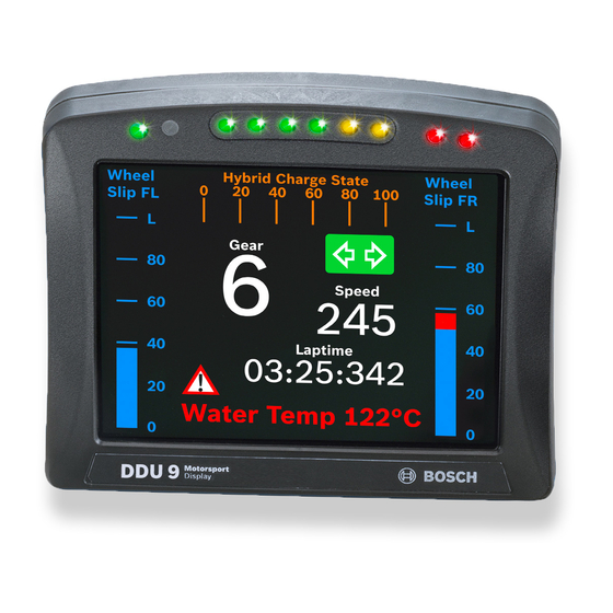
- Page 1 Display DDU 9 Manual Version 1.0 14/03/2019...
-
Page 2: Table Of Contents
12.3 Configuring computed sources ..................................12.4 Hysteresis..........................................13 Online Measurement ..............................13.1 Setting up an online measurement................................13.2 Online calibration of measurement channels............................13.3 Group adjustment ........................................ 13.4 Online calibration of multipoint adjustment channels .......................... ii / 148 DDU 9 Bosch Motorsport... - Page 3 18.1 Firmware and configuration ..................................... 18.2 Firmware update........................................19 Clone the Unit ................................. 20 Fuel Consumption Calculation ............................20.1 Setting up fuel consumption calculation and tank management ..................... 20.2 Fuel consumption diagnosis/counter reset..............................20.3 Example ............................................ 21 RaceCon Shortcuts................................Bosch Motorsport DDU 9 iii / 148...
-
Page 4: Onboard Network Concept
(e.g. wheelspeed) SENSPWR5 As short as possible active ANA_IN(xy) LS_GND_1 Sensor LS_GND_2 ANA_IN(xx) Sensor Engine_GND SENSGND NOTICE This schematic is not device specific, please see the section “Technical Data for the spe- cifications of your device. 4 / 148 DDU 9 Bosch Motorsport... -
Page 5: Preparation
Preparation | 2 2 Preparation Use the DDU 9 only as intended in this manual. Any maintenance or repair must be per- formed by authorized and qualified personnel approved by Bosch Motorsport. Operation of the DDU 9 is only certified with the combinations and accessories that are specified in this manual. -
Page 6: Power Supply
– KL 30 is an unswitched battery positive rail (same as battery positive terminal) – KL 31 is an unswitched ground rail (same as battery negative terminal) Be careful to observe current limits of wires and connector pins! 6 / 148 DDU 9 Bosch Motorsport... -
Page 7: Error Memory
DDU 8. Please consider this and replace the product name ‘DDU 8’ in this case with the name of your product. 4.1 Error memory representation in RaceCon Bosch Motorsport devices feature an error memory. Information on errors can be visual- ized via RaceCon (online measurement) or can be transmitted via telemetry. 4.1.1 Accessing the memory... - Page 8 The error memory is not cleared by a configuration download and is not cleared by a power cycle. 4.1.2 Clearing the error memory There are two ways of clearing the error memory, both are shown in the following illustra- tion: 8 / 148 DDU 9 Bosch Motorsport...
-
Page 9: Information On Errors Available From The Error Memory
1: at least one inactive error present in memory, no active errors 2: at least one active error present in memory If displayed in a measurement sheet, this property’s value (0, 1 or 2) is translated into a verbal description: Bosch Motorsport DDU 9 9 / 148... - Page 10 0 (no error present in memory): No orange border MIL off (black) No entries 1 (at least one inactive error present in memory, no active errors): Constantly orange border MIL constantly orange Info cycling through errors, present in error memory 10 / 148 DDU 9 Bosch Motorsport...
- Page 11 All failure modes are continuously diagnosed; any error detected will be written to the error memory. Once an error is detected, it is qualified as “active”. – 1 (TRUE) Error was detected in most recent diagnose run (active) Bosch Motorsport DDU 9 11 / 148...
- Page 12 (while more than one error is active) and watch the values change periodically: The verbal representation of the numerical codes of these labels can be visualized in the properties window of the measurement page: 12 / 148 DDU 9 Bosch Motorsport...
-
Page 13: Analog Input Diagnosis
The pin diagnosis functionality (check whether measurement is within the desired range) can be activated in the ANA pin setup wizard; to allow for a diagnosis regarding shortcut to ground, shortcut to battery voltage and cable breakage, a minimum / maximum has to be defined. Bosch Motorsport DDU 9 13 / 148... - Page 14 Open the Error Memory of the Device. Click "start detection of cable". Check the Error Memory for new fault entries, regarding "Open line errors". 14 / 148 DDU 9 Bosch Motorsport...
-
Page 15: Technical Data
CCP-Master, data acquisition from ECU that support CAN calibration protocol (optional) Mechanical Data Size 151 x 126 x 33.5 mm Weight 540 g Protection Classification IP54 to DIN 40050, Section 9, Issue 2008 Operating temperature internal -20 to 85°C Operating temperature Display -20 to 70°C Bosch Motorsport DDU 9 15 / 148... - Page 16 USB_DATA F 02U V02 214-01 USB-Port unlocked (Rugged USB flash drive Bosch File System (BFS) format included, works with Bosch File System (BFS) pre- formatted USB Flash drive only) Adapter cable to USB-Port (included in Up- F 02U V01 343-01...
- Page 17 Sens_Gnd_4 fused Incl. Sens_Power 5V over current protected Incl. ANA_IN_3 3.01 kOhm switchable Incl. ANA_IN_4 3.01 kOhm switchable Incl. Time_Sync connection to Bosch ECU Incl. CAN_1_L CAN speed selectable Incl. Ethernet_screen Incl. Ethernet_2_RXN Incl. Sens_Gnd_3 fused Incl. Sens_Power 5V over current protected Incl.
- Page 18 5 | Technical Data Name Comment Status USB_Device_DN to Bosch USB stick Opt. RS232_RX_Telemetry e.g. GSM telemetry Incl. Ethernet_1_TXN Incl. Sens_Gnd_1 fused Incl. ANA_IN_11 3.01 kOhm switchable Opt. ANA_IN_9 3.01 kOhm switchable Opt. RS232_TX_GPS Incl. ANA_IN_16 3.01 kOhm switchable Opt.
-
Page 19: Disposal
Hardware, accessories and packaging should be sorted for recycling in an environment- friendly manner. Do not dispose of this electronic device in your household waste. Waste electronic equipment must be disposed of properly according to Electrical and Electronics Act (ElektroG) and the European WEE directive. Bosch Motorsport DDU 9 19 / 148... -
Page 20: Inputs And Outputs
7.2 Output channels Sensor power supply The DDU 9 has four sensor power supplies:2 x 5 V, 1 x 10 V and 1 x Ubat regulated voltage. They are short circuit protected to battery voltage and GND. 7.3 Communication channels CAN bus The DDU 9 has two CAN buses configurable as input and output. - Page 21 Inputs and Outputs | 7 Name Description Used for DDU 9 Pin 10 K-Line ECU diagnosis Pin 8 Ethernet RxD + Ethernet interface Pin 9 Ethernet RxD - Ethernet interface Pin 11 Ethernet TxD + Ethernet interface Pin 12 Ethernet TxD -...
-
Page 22: Mechanical Drawing
8 | Mechanical Drawing 8 Mechanical Drawing 22 / 148 DDU 9 Bosch Motorsport... -
Page 23: Starting Up
– The ethernet port has “cable auto crossover” functionality 9.1.1 Starting the unit The DDU 9 powers up by turning on the ignition of the car. At startup the DDU 9 will dis- play a Bosch logo. After a moment the DDU 9 shows a display element screen. - Page 24 Troubleshooting while setting up the network interface The DDU 9 contains a DHCP server, network addresses can be assigned automatically to the configuration PC. In case of problems during the network connection, please try the following steps: Switch off the PC’s firewall.
- Page 25 Start the RaceCon software. In the ‘File’ menu select ‘New project’ to create a new project. In the Toolbox select the DDU 9 and drag it into the Main Area. A pop up window to specify the DDU 9 program archive appears.
- Page 26 An information shows if the archive is valid or not. Click ‘Next’. Select ‘Race track’ or ‘Testbench’ mode according to your application. Click ‘Finish’. The DDU 9 is inserted into the project and RaceCon tries to connect to the device. 26 / 148 DDU 9 Bosch Motorsport...
- Page 27 Starting up | 9 RaceCon detects configuration differences between the DDU 9 and the RaceCon pro- ject and asks for permission for data download. Click ‘Yes’ to download the configurations to the device or ‘No’ to continue without downloading the data.
-
Page 28: Feature Activation
– The feature activation status is stored permanently in the device and requires activat- ing once only. – As the activation key is device specific, a key delivered with one DDU 9 does not work on any other DDU 9 . - Page 29 Starting up | 9 Ensure a connection to the device. To activate a feature, double-click on ‘DDU 9’ in the Project Tree. Click on the ‘Features info’ tab in the Main Area. 1st: Double-click on DDU 2nd: Click on 'Features info' The ‘DDU 9 features info’...
-
Page 30: First Display Configuration (Quick Start)
9 | Starting up Perform these steps to activate other features you purchased. Switch the car’s ignition off and on again to cycle the power of DDU 9. 9.3 First display configuration (Quick Start) This chapter explains the configuration of a display element showing the battery voltage. - Page 31 Search for 'ub' Drag the ‘ub’ measurement channel from the ‘Data’ window and drop it on the dis- play element. Drag + Drop Click on the ‘Download’ button in the upper left corner. Bosch Motorsport DDU 9 31 / 148...
-
Page 32: First Recording (Quick Start)
9 | Starting up The configuration download starts and the DDU 9 carries out a reset. The status signal in the upper left corner switches to green. The value of the battery voltage is displayed on the DDU 9. 9.4 First recording (Quick Start) This chapter explains the configuration of the recording of the battery voltage channel. - Page 33 Drag + Drop Click on the ‘Download’ button in the upper left corner. The configuration download starts and the DDU 9 carries out a reset. Now you can find the ‘ub’ measurement channel in the ‘Data Area’. As we did not define global start conditions, recording starts immediately.
- Page 34 12. Click on the ‘Current Import’ tab. 13. Click on ‘Import’ in the lower right corner. If the ‘Import all on connect’ box is checked, the data transmission from the DDU 9 starts automatically. Measurement files are stored automatically in the folder defined under ‘Settings’.
-
Page 35: Set Time And Date
The ‘ub’ measurement channel‘s graph is displayed. 9.5 Set time and date The DDU 9 is equipped with a real time clock which is supplied by an internal accumu- lator. Once this accumulator is charged correctly by 12 V supply of the display, ‘Date &... - Page 36 9 | Starting up Alternatively, click on ‘Set Date & Time’ in the context menu of the device. A ‘Set Date & Time’ menu opens Set the current local date and time as coordinated universal time. 36 / 148 DDU 9 Bosch Motorsport...
- Page 37 Starting up | 9 At ‘Set a specific date & time’ click and type on the value you want to change, or choose from the dropdown menu. Bosch Motorsport DDU 9 37 / 148...
-
Page 38: Display Configuration
A new empty page opens. 10.1.3 Selecting display pages Click on ‘DDU 9’ in the DDU 9 Project Tree, then on ‘Display’ and double-click on the page you want to select (example: ‘New Page’). In the Main Area, a representation of the DDU 9 opens. -
Page 39: Display Element Configuration
Drag + Drop Drag a measurement channel from the Data Area and drop it on the numeric display element. Bosch Motorsport DDU 9 39 / 148... - Page 40 10 | Display Configuration The measurement channel is linked to the numeric display element. Drag + Drop 40 / 148 DDU 9 Bosch Motorsport...
- Page 41 10.2.2 Bargraph display element Bargraph display element Drag the ‘Bargraph’ display element from the Toolbox and drop it on the display page. Configuring a ‘Bargraph’ display element Double-click on the ‘Bargraph’ display element. The Bargraph Wizard window opens. Bosch Motorsport DDU 9 41 / 148...
- Page 42 – Alarm Icon: An alarm displaying a defined image (e.g. a warning triangle) Adding an ‘Alarm’ display element to display page Drag an ‘Alarm’ element from the Toolbox and drop it on the display page. 42 / 148 DDU 9 Bosch Motorsport...
- Page 43 (only possible if Alarm is resettable). e) Enter the time until the Alarm can appear again after a reset. Click ‘OK’ when done. Copy alarm to all display pages by clicking ‘Move to’ -> ‘All Pages’. Bosch Motorsport DDU 9 43 / 148...
- Page 44 Switch to the tab ‘Alarm representation’. It is configured in the same way as the ‘Alarm’ text display element. Click ‘OK’ when done. NOTICE If several active alarms in the display overlap, each alarm is in the foreground for 2 seconds. 44 / 148 DDU 9 Bosch Motorsport...
- Page 45 Adding a Label or picture display element to display page Drag the Label or picture display element from the Toolbox and drop it on the display page. Configuring a Label display element Double-click on the Label display element. The Label Wizard window opens. Bosch Motorsport DDU 9 45 / 148...
- Page 46 Example: The text color changes from white to red when the battery voltage is fewer than 12 V. Conditional Formatting is available at numeric, ‘Bargraph’ and ‘Alarm’ display element. Double-click on the display element. The Numeric Wizard window opens. Switch to the tab ‘Conditional Formatting’. 46 / 148 DDU 9 Bosch Motorsport...
-
Page 47: Leds
10.3.1 Configuring shift LEDs To use shift LEDs, RPM and gear measurement channels an ECU has to be loaded in Race- Con. Click on the tab ‘LEDs’ in the display view. Click on the button ‘Add shift lights’. Bosch Motorsport DDU 9 47 / 148... - Page 48 Choose the measurement channel for ‘Gear’. Gear must have an ASCII quantization (1st gear=‘1’= 49, 2nd gear=‘2’= 50, …). (ASCII quantization is standard for the ‘gear’ channel of Bosch ECUs. If you get the gear information of a different control unit as the Bosch ECU (e.g. a gearbox control unit), use the Gear Lookup Table to translate numeric values to ASCII format.
- Page 49 Enter the name and an optional description of the translated ASCII measurement channel. Click ‘Ok’ when done. A graphic shows the connection between the input and output channels. The measure- ment channel can now be used in the shift LED configuration. Bosch Motorsport DDU 9 49 / 148...
- Page 50 ‘Display “on” pattern’ and define the LEDs in the one color. Then choose ‘Display “off” pattern’ and define the LEDs in the other color. Click ‘OK’ when done. The configuration is displayed in the DDU 9 LED Configuration window. 10.3.4 Assigning display pattern priority Assigning display pattern priority You can assign the priority of the created display pattern and shift lights.
-
Page 51: Page Select / Display Brightness / Led Brightness
If the channel value does not only consist of integers, the pages will be switched as fol- lows: Page 1 is shown with the value < 1.5 Bosch Motorsport DDU 9 51 / 148... - Page 52 Connect a 6 or 12 position switch to one of the analog input pins ANAxx and to the sensor ground. For recommended position switches, please see the environment section in the chapter “Technical Data.” Select one of the analog inputs in the project tree. 52 / 148 DDU 9 Bosch Motorsport...
- Page 53 Go to ‘Measurement Sources’ in the toolbox and select the ‘Characteristic Curve’ un- der ‘Analog sources’. Drag and drop it on the selected analog input channel in the project tree. Select ”Pull-up value:” 3.01 kOhm and click on ‘Next’. Bosch Motorsport DDU 9 53 / 148...
- Page 54 R: Resistor for each Rotary switch position (Ohm) 3010: Pull-up resistor (Ohm) The following screenshot and the data are an example for a Bosch switch. Define minimum and maximum Limit. Select “Output data type” from 8, 16 or 32 Bit.
- Page 55 Display Configuration | 10 Define Name and Description and click on ‘Ok’. Click on the ‘Display’ tab and select the ‘Settings’ tab at the bottom. Bosch Motorsport DDU 9 55 / 148...
- Page 56 You will see a graphical display with the raw and the physical value of the channel. 10.4.3 Option 2: Up/Down switches Define either one signal for a wrap around switch or two signals for an up/down switch. Select the ‘Display Switch’ and drag it into the DDU 9. 56 / 148 DDU 9 Bosch Motorsport...
- Page 57 (by switching) in a loop, after the last page it starts again with the first page. If you choose “Display switch does not wrap around”, you need two switches to turn the pages in both directions. Define Name and Description and click on ‘Ok’. Bosch Motorsport DDU 9 57 / 148...
- Page 58 10 | Display Configuration In the project tree, select “Display” and then “Open”. To use the channel as a Page Switch, check the box "Use a channel to switch pages" and select the channel configured above. 58 / 148 DDU 9 Bosch Motorsport...
- Page 59 In the project tree, select “Download configuration”. If you want to check your configured channel, reassure that the device status is green, double-click on the DDU 10 and select the "Statistics" tab. The configured channel position opens. Bosch Motorsport DDU 9 59 / 148...
- Page 60 10 | Display Configuration 10.4.4 Option 3: CAN input signal, math channel or ANA_IN channel Define your CAN, math or analog input channel. Select the 'Display' tab and then the 'Settings' tab at the bottom. 60 / 148 DDU 9 Bosch Motorsport...
- Page 61 To use a channel as a Page Switch, check the box" Use a channel to switch page" and select the channel configured above. Click on the ‘Download’ button in the upper left corner. Bosch Motorsport DDU 9 61 / 148...
-
Page 62: Math And Condition Channels
– Result can be used as input source for various display elements (numeric elements, alarms, Bargraphs) and further calculations in the whole RaceCon project All math channels can be used globally in the whole DDU 9 project. 10.5.2 Creating a new math channel Follow the steps shown in the screenshot. - Page 63 Define a value that can be used as a constant in the formula. g) Choose a function. h) Describes the function selected above. Click ‘Finish’ when done. The math channel is displayed in the DDU 9 math channel window. 10.5.3 Creating a new conditional function Follow the steps shown in the screenshot.
- Page 64 – when If-condition changes state from FALSE to TRUE. An example of a condition to set up the maximum front brake pressure is given on the next page. The conditional function is displayed in the DDU 9 math channel window. 64 / 148 DDU 9...
-
Page 65: Condition Channels
– Result can be used as input source for Alarm display elements and further calculations in the whole RaceCon project. Condition combination – Combination of several (up to 16) condition channels for more complex calculations Bosch Motorsport DDU 9 65 / 148... - Page 66 10 | Display Configuration – Logical results All conditions can be used globally in the whole DDU 9 project. 10.6.1 Creating a new condition channel Follow the steps shown in the screenshot. : Double- click on ‘Conditional Channels” in Project Tree : Click on ‘Add condition”...
- Page 67 Toggling output: Result is a pulse that lasts until the next condition is fulfilled. Click ‘Ok’ when done. The conditional channel is displayed in the DDU 9 condition channel window. 10.6.2 Creating a new condition combination Follow the steps shown in the screenshot.
-
Page 68: Cpu Load Limits
The conditional combination is displayed in the DDU 9 condition channel window. 10.7 CPU Load Limits As all microprocessors, the DDU 9’s processor has limited capacities. The current load of the processor can be monitored using the channel “cpu_load”. When configuring your device, please make sure the used CPU load is in a save range below 100 %. - Page 69 – Logger configuration (total logging rate [kB/s], conditional measurement rates) To help respecting the limit of 85 % CPU load, the DDU 9 creates an error memory entry. To trigger this error entry, the CPU load must exceed the limit for 5 minutes without inter- ruption.
-
Page 70: Can Bus
– Baudrate (125 kbaud to 1 Mbaud) – 11 Bit or 29 Bit identifiers – Input configuration: Read messages from CAN bus and convert to DDU 9 measure- ment/display variables. CAN bus supports row counter configuration. – Output configuration: Write RaceCon measurement variables to CAN messages, out- put frequency and row counter are configurable, CAN gateway functionality (transfer from one bus to another). -
Page 71: Can Input
11.2.1 Create new CAN Input channel Double-click on any CAN bus item, to open the "CAN messages overview". Select ‘Add CAN-IN’ and choose the desired CAN bus for the new input channel. A CAN channel configuration window opens. Bosch Motorsport DDU 9 71 / 148... - Page 72 11 | CAN Bus Insert the name and description of the channel. Click ‘OK’ when done. The channel is listed in the Data window. 72 / 148 DDU 9 Bosch Motorsport...
- Page 73 Enter data position, length and format. e) The bargraph shows assignment of the bytes. - Red colored fields show the assignment of the data bytes. - Orange colored fields show the assignment of the multiplexer bytes. Bosch Motorsport DDU 9 73 / 148...
- Page 74 Special features CAN analyzer functionality This functionality is only available, if a MSA-Box (I or II) is used to connect the DDU 9 to the PC. Choose the CAN bus that is connected to the MSA-Box to display the raw value and the converted physical value here.
-
Page 75: Can Output
For an online view of the value measured by the DDU 9 , insert the channel in an online measurement sheet which is described in the chapter Setting up an online measurement [} 98]. - Page 76 Enter name of message, description, CAN-Id and Grid (output interval). Optionally, specify a multiplexer. Definition of CAN message Content of message Click on ‘Add channel’ or ‘Add constant’, this opens the ‘Add new CAN out channel’ window. 76 / 148 DDU 9 Bosch Motorsport...
- Page 77 Click ‘Add constant’. The ‘Add new CAN Out constant’ window appears. Define the name of the constant, the required value in hex and define the CAN chan- nel settings. Click ‘OK’ when done. Click here Bosch Motorsport DDU 9 77 / 148...
-
Page 78: Analog And Frequency Inputs
Filtered physical value Filtered channels are routed through digital low pass filters: – DDU 9 uses A/D converter oversampling and digital filtering to recording rate – Digital filters eliminate ‘out-of-band’ noise – Cut-off frequency automatically adjusted to recording rate –... -
Page 79: Configuring Inputs
'Bosch Sensor Wizard' Click on ‘Measurement Sources’ in the Toolbox. To expand the list of ‘I/O Channels’, click on ‘+’ in the DDU 9 Project Tree. Drag the “Bosch Sensor Wizard” from the Toolbox and drop it on the desired analog input channel in the DDU 9 Project Tree. - Page 80 Click ‘Finish’ when done. The “Create channel” window opens. Enter the channel name and description. Click ‘Ok’ when done. The channel is inserted into the DDU 9 Project Tree. Channel is linked to ANA03 Calculation of Input pin Pull-up...
- Page 81 To activate the internal pullup-resistor, check the box. The internal pullup-resistor is used to get a 5 V signal at the analog channel of the DDU 9. It allows you to use a push-button. The fixed value of the internal pullup-resistor is 3,010 Ohm. If using an additional external pullup-resistor, set up the overall resistance.
- Page 82 Working with automatically created measurement sheets is ex- plained in chapter ‘Setting up an online measurement [} 98]’. Click ‘Finish’ when done. Enter a channel name and a description. Click ‘OK’ when done. The channel is inserted into the DDU 9 Project Tree. 82 / 148 DDU 9 Bosch Motorsport...
- Page 83 Thermistor Click ‘Measurement Sources’ in the Toolbox. To expand the list of ‘I/O Channels’, click on ‘+’ in the DDU 9 Project Tree. Drag the “Characteristic Curve” analogue signal source from the Toolbox and drop it on the desired analogue input channel in the DDU 9 Project Tree.
- Page 84 To activate the internal pull up-resistor, check the box. The DDU 9 pull up-resistor is used to get a 5 V signal at the analogue channel of the DDU 9. It allows you, to use a push-button. The fixed value of the internal pull up-resistor is 3,010 Ohm. If using an additional external pull up-resistor, set up the overall resistance.
- Page 85 Click ‘Finish’ when done. Enter channel name and description. Click ‘OK’ when done. The channel is inserted into the DDU 9 Project Tree. Channel is linked to ANA05 Characteristic Adjustment curve for sensor is disabled...
- Page 86 – Curve definition by online adjustment at vehicle Click on ‘Measurement Sources’ in the Toolbox. Expand the list of ‘I/O Channels’ by clicking on ‘+’ in the DDU 9 Project Tree. Drag the ‘Multipoint Adjustment’ analog signal source from the Toolbox and drop it on the desired analog input channel in DDU 9 Project Tree.
- Page 87 To activate the internal pullup-resistor, check the box. The internal pullup-resistor is used to get a 5 V signal at the analog channel of the DDU 9. It allows you to use a push-button. The fixed value of the internal pullup-resistor is 3.01 kOhm. If using an additional external pullup-resistor, set up the overall resistance.
- Page 88 Click ‘Finish’ when done. Enter channel name and description. Click ‘OK’ when done. The channel is inserted into the DDU 9 Project Tree. Channel is linked to ANA06 Characteristic Adjustment curve for sensor is enabled...
- Page 89 Online definition of the curve is covered in the chapter ‘Online calibration of measurement channels [} 103]’ of this manual. NOTICE Working with automatically created measurement sheets is ex- plained in chapter ‘Setting up an online measurement [} 98]’. Bosch Motorsport DDU 9 89 / 148...
- Page 90 12 | Analog and Frequency Inputs 12.2.5 Digital filter details DDU 9 uses A/D converter oversampling and digital filtering to recording rate. Digital filters eliminate ‘out-of-band’ noise Cut-off frequency automatically adjusted to recording rate Example: – 100 Hz recording rate (10 ms) –...
- Page 91 – Calculation of wheel speed with wheel circumference Click on ‘Measurement Sources’ in the Toolbox. To expand the list of ‘I/O Channels’, click on the ‘+’ in the DDU 9 Project Tree. Drag the ‘Velocity’ digital signal source from the Toolbox and drop it on the desired ‘REV’...
- Page 92 Enter name to automatically create a new measurement sheet Click ‘Finish’ when done. Enter the channel name and description. Click ‘OK’ when done. The channel is inserted into the DDU 9 Project Tree. Channel is linked to REV01 Input pin Number of...
-
Page 93: Configuring Computed Sources
Example: Sensitivity/offset calculation on input channel Click ‘Measurement Sources’ in the Toolbox. Drag the ‘Sensitivity/Offset’ computed source from the Toolbox and drop it on ‘Com- puted Channels’ in the DDU 9 Project Tree. Drag + Drop A ‘Computed Sensitivity/Offset Wizard’ opens. -
Page 94: Hysteresis
Click ‘Finish’ when done. Enter channel name and description. Click ‘OK’ when done. The channel is inserted into the DDU 9 Project Tree. NOTICE Working with automatically created measurement sheets is ex- plained in chapter ‘Setting up an online measurement’. - Page 95 Enter name to automatically create a new measurement sheet Click ‘Finish’ when done. Enter channel name and description. Click ‘OK’ when done. The channel is inserted into the DDU 9 Project Tree. Channels available in Computed sources Calculation of hysteresis channel...
- Page 96 Click on ‘Measurement Sources’ in the Toolbox. Drag the ‘Speed’ computed source from the Toolbox and drop it on the project name in the DDU 9 Project Tree. Do not drop it on ‘DDU 9’! Drag + Drop A ‘Calculated Speed Wizard’ opens.
- Page 97 Choose driven axle Choose individual wheel speed channels Set limit for speed difference for calculation Click ‘Finish’ when done. The speed calculation is inserted into the DDU 9 Project Tree. Speed calculation in DDU Project Tree Measurement channels calculated speed...
-
Page 98: Online Measurement
– Communication protocol: XCP 13.1 Setting up an online measurement DDU 9 supports online measurement of sensor values and diagnostic variables. Expand ‘Measurement Container’ and ‘Measurement Folder 1’ in the Project Tree and double-click on ‘Sheet1’. Alternatively, click on the ‘Calibration/Measuring’ tab to open the window directly. - Page 99 To change between different sheets, click on the tabs on the bottom of the ‘Calibra- tion/Measuring’ window. Tabs to switch between sheets To add an element to a measurement sheet, perform the following steps: Drag a measurement element from the Toolbox and drop it on the measurement sheet. Bosch Motorsport DDU 9 99 / 148...
- Page 100 Drag + Drop Select the desired measurement channel from the ‘Data’ area and drop it on the measurement element. If the DDU 9 shows the green status, the value is displayed. Drag + Drop RaceCon offers different types of measurement elements:...
- Page 101 Oscilloscope (Chart) 13.1.1 Automatic creation of measurement sheets RaceCon can create measurement sheets automatically. You can create and use measurement sheets with the DDU 9 as well as with all other devices connected to RaceCon. Drag + Drop During the configuration of a measurement channel, select a measurement sheet from the list box or enter a name for a new measurement sheet.
- Page 102 The automatically created sheet is inserted in the Project Tree under ‘Measurement Container’ and ‘Device Channels’. If the DDU 9 is connected to RaceCon and the status is green, live values of the channels are shown. 13.1.2 Using the measurement sheets When RaceCon is online, press the ‘F11’...
-
Page 103: Online Calibration Of Measurement Channels
– Analog sensors drift with age, temperature, etc. – Manual calibration is necessary – Solution: online offset calibration – Example: acceleration sensor 13.2.1 Enable online offset calibration for measurement channel During creation of the measurement channel Bosch Motorsport DDU 9 103 / 148... - Page 104 13.2.2 Performing the online offset calibration DDU 9 has to be connected to RaceCon to calibrate the sensor’s offset. Apply the desired physical condition to the sensor (e.g. 1 G to an acceleration sensor). Open the measurement channel’s online page by double-clicking on the measure- ment channel name in the Data Area.
-
Page 105: Group Adjustment
– A group of input channels linked to the group adjustment event 13.3.2 Setting up the group adjustment trigger channel Click ‘Measurement Sources’ in the Toolbox. Drag the ‘Group Adjustment Channel’ element from the Toolbox and drop it on the DDU 9 Drag + drop A ‘Group Adjustment Channel Wizard’ opens. - Page 106 Double-click on the created channel (e.g. ‘grp_adj_channel’) in the Project Tree. In the Main Area, an overview of the available adjustment channels opens. To add measurement channel(s) to the group adjustment event, check the ‘Calibrate’ box of the desired channel(s). 106 / 148 DDU 9 Bosch Motorsport...
- Page 107 Make sure the pullup-resistor is enabled, if you selected ‘active low’ trigger polarity. Double-click on the input channel ‘grp_adj_channel’ of the group adjustment. Download the configuration on the DDU 9. To connect the DDU 9 to RaceCon, see chapter ‘Connecting the Unit to RaceCon’.
-
Page 108: Online Calibration Of Multipoint Adjustment Channels
Create a multipoint adjustment measurement channel. To create a multipoint channel, see chapter ‘Configuring a multipoint adjustment’. Download the configuration on the DDU 9. To connect the DDU 9 to RaceCon, see chapter ‘Connecting the Unit to RaceCon’. Click on the desired channel in the DDU 9 Project Tree. - Page 109 10. Click ‘Close’ when done. The calibration curve is displayed in the online view. Adjustment points vs. offset adjustment Overall offset adjustment of all curve points. Calibration of E.g. to compensate individual sensor drift curve points wheel_FR wheel_FR Bosch Motorsport DDU 9 109 / 148...
-
Page 110: Recording
Variables can be grouped Tabs to access conditions, settings and statistics To add measurement channels to a recording, click ‘DDU 9’ in the DDU 9 Project Tree. In the Data Area, the measurement channels are displayed. Drag and drop desired measurement channels into recording group. - Page 111 Using fast block/slow block transmission DDU 9 telemetry uses available bandwidth of Telemetry Unit FM 40 (19,200 baud -> ap- prox. 1,700 bytes/s). The bandwidth has to be divided into channel information to be transmitted high-frequently and low-frequently using the ‘fast/ slow block’ setting.
- Page 112 To add a new group, select ‘Add group’ in the context menu of the recording. The groups can be renamed to ‘Gearbox’, ‘Aero’, ‘Engine’, etc. 14.2.3 Global settings To display the global DDU 9 settings, select the ‘Settings’ Tab. 112 / 148 DDU 9...
- Page 113 The overview helps to detect bandwidth bottlenecks of channels. Bandwidth bottlenecks can be solved by changing the ‘fast/slow block’ setting for each channel. The data rate of the whole system is often less than the data rate of the DDU 9 and limits the overall transmission speed.
- Page 114 14 | Recording 14.2.5 Recording diagnosis The channel ‘statectrl_ok’ of the DDU 9 can be used for online monitoring of recording status. Value Name RECORD DATAOK BLKOK STARTED Content of status bits Name Bitset Bit cleared RECORD Measurement data is re- No measurement data will be stored because meas- corded.
-
Page 115: Recording Data On Usb Device
Power on the system and connect with RaceCon to the vehicle. Download the configuration to the DDU 9. Record measurement data. If an USB device is present, the DDU 9 stores the data in parallel on the internal memory and the USB device. - Page 116 11. Click on ‘Settings’ tab and select the option ‘Flash Card/USB Stick’. Choose your DDU from dropdown list 12. Activate ‘Apply changes’. Insert the USB device into the PC. Data transmission from device starts automatically. Measurement files are stored automatically in the base folder. 116 / 148 DDU 9 Bosch Motorsport...
- Page 117 17. Click in ‘New Desktop‘ to open a new measurement data window. 18. Drag the desired measurement channel from the Channel list and drop it into the measurement data window. The measurement channel‘s graph is displayed Bosch Motorsport DDU 9 117 / 148...
- Page 118 DDU 9 still records data. If the USB device is unplugged and re-inserted for > 4 s while the DDU 9 is powered up or a different USB device is plugged in, the DDU 9 restarts. In this case, the DDU 9 is not op- erational for 1.5 s.
- Page 119 5: Error: Media error The communication to the USB device broke down. The USB device is defect. The USB device is not supported by DDU 9. 6: Error: Media corrupt The USB device is not in valid BFS format. (Hint: Re-format the USB device in RaceCon.)
-
Page 120: Lap Trigger
Lap Trigger Transmitter Lap Trigger Receiver 15.1.1 Electrical trigger signal In DDU 9 all sources of measurement channels can be used as trigger signal. – Analog input – Digital input – CAN input Signal (measurement channel) properties Low active signal (Bosch triggers): Trigger releases if signal is below the threshold. - Page 121 Under race conditions, trigger signals are sometimes missed. Software functionality intro- duces ‘forced trigger’. 15.1.4 Setting up a lap trigger Click ‘Measurement Sources’ in Toolbox. Drag ‘Laptrigger’ into ‘System Overview’. Do not drop it on ‘DDU 9’! Bosch Motorsport DDU 9 121 / 148...
- Page 122 Choose the signal channel for the trigger signal Choose the source for the vehicle speed Enter the distance of the racetrack Click ‘Finish’ to complete the operation. A pre-configured lap trigger window opens. 122 / 148 DDU 9 Bosch Motorsport...
- Page 123 'best laptime' is accepted Preset value for 'best laptime' Change signal for vehicle speed, if desired. Enter minimum speed for trigger release. Define settings for distance based retrigger protection. Define settings for distance based forced trigger. Bosch Motorsport DDU 9 123 / 148...
- Page 124 Only applicable for a GPS Laptrigger Define the latitude and longitude of the GPS detection point. Define the detection range around the detection point. Define the channel sources for Longitude, Latitude, Direction and Speed. 124 / 148 DDU 9 Bosch Motorsport...
- Page 125 The GPS lap trigger uses a GPS signal to trigger the lap timer. To function this timer an ex- ternal GPS sensor (see GPS Sensor) has to be connected to the device and a detection point with a detection range has to be defined in RaceCon. Bosch Motorsport DDU 9 125 / 148...
- Page 126 Speed. NOTICE The configuration of the sensor update rate and the detection range must insure to receive a valid GPS point in the detection range, des- pite the occurring vehicle speed near the detection point. 126 / 148 DDU 9 Bosch Motorsport...
-
Page 127: Counting Outing/Laps/Fragments
Fractr Fragment counter Counting in WinDarab To automatically name recorded files use filename templates in WinDarab dialog: Filename template Function [outing] Value of outing counter [lap] Value of lap counter [fragment] Value of fragment counter Bosch Motorsport DDU 9 127 / 148... -
Page 128: Lap Timing
15.3.2 Distance based retrigger protection Trigger is locked until configured min distance (i.e. 80 % → 3200 m) of track distance (i.e. 4000 m) has been covered. To deactivate distance based retrigger protection, set min dis- tance to 0 %. 128 / 148 DDU 9 Bosch Motorsport... - Page 129 To deactivate distance based forced triggers, uncheck box. Change signal for vehicle speed, if desired. Enter minimum speed for trigger release. Define settings for distance based retrigger protection. Define settings for distance based forced trigger. Bosch Motorsport DDU 9 129 / 148...
-
Page 130: Segment Timing
Define settings for lap timing (main trigger). Define settings for sub trigger. Not applicable with a GPS lap trigger. Sub Trigger Trigger Sub Trigger Main Trigger The sub trigger mode cannot be used with the GPS lap trigger. 130 / 148 DDU 9 Bosch Motorsport... -
Page 131: Countdown Timer
The trigger signal starts a timer countdown. The current value of the timer is stored in the variable Laptrigger_cntdown_dls which can be displayed. Define settings for countdown timer. Bosch Motorsport DDU 9 131 / 148... -
Page 132: Gps Sensor
Baud rate: 9,600 is standard for GPS, DDU 9 supports 1,200 to 115,200 baud. GPS Rx inter- face baud rate must match DDU 9 interface baud rate. DDU 9 Baud rate can be set with the ‘GPS_BAUDRATE’ characteristic Data format: DDU 9 expects 8 data bits, no parity bit, 1 stop bit (8N1) 16.2 Protocol... - Page 133 For a good signal quality we recommend 115,200 baud. – Click on “Send” to store the new setting in “U-Center”. – Click on “CFG (Configuration)”. – Click on “Send” to save the new setting on the sensor. Bosch Motorsport DDU 9 133 / 148...
- Page 134 – Set the ticks as shown in the following picture. – Click on “Send” to store the new setting in “U-Center”. – As during configuration step 1, click on “CFG (Configuration)”. – Click on“Send” to save the new setting on the sensor. 134 / 148 DDU 9 Bosch Motorsport...
-
Page 135: Measurement Labels
– Click on“Send” to save the new setting on the sensor. NOTICE Sensor needs reception for visible signal. It takes time to start the sensor. 16.4 Measurement labels The decoded NMEA messages are copied to these DDU 9 measurement labels. Measurement label Function gps_PDOP Position Dilution Of Precision... -
Page 136: Gps Troubleshooting
Is the sensor connected to the „sensor ground“ of the device? Interface Do the baud rates of the GPS sensor and the DDU 9 match? Is the GPS sensor set up for 8N1 transmission parameters? Is the GPS sensor set up for NMEA messages? Are the GGA, VTG, RMC messages activated? 136 / 148... - Page 137 A correct reception is indicated when ‘gps_fix’ is showing ‘3D Fix’. GPS sensor values are frozen Does the sensor has lost its reception? The old values will be kept if the reception is lost. The gps_smask channel shows which NMEA sentence is received. Bosch Motorsport DDU 9 137 / 148...
-
Page 138: Predated Laptime
The channel Laptrigger_lapdiff_pred_dls is updated as soon as the main lap trigger is re- ceived. Both other channels are updated as soon as the next segment distance is travelled or the next intermediate trigger is received. 138 / 148 DDU 9 Bosch Motorsport... -
Page 139: Firmware
Recorded data: Measurement data recorded during vehicle operation. 18.2 Firmware update The scheme shows the process during each connection between RaceCon and DDU 9. 18.2.1 Performing the firmware update Firmware update is only possible if the DDU 9 is connected to RaceCon. - Page 140 18 | Firmware The configuration of Input channels, CAN I/O, display, recording + telemetry will not be changed. In the DDU 9 Project Tree, right-click on ‘DDU 9’ and choose ‘Synchronize’ then ‘Up- date firmware’. A pop-up menu opens. Select the destination of the firmware archive (PST).
- Page 141 Firmware | 18 When the firmware update is complete, the DDU 9 displays the message ‘Updating firmware finished. Do a powercycle.’ Switch the car’s ignition off and on again to cycle the power of the DDU 9. Bosch Motorsport DDU 9...
-
Page 142: Clone The Unit
19 Clone the Unit To replace a DDU 9 by another device, it is possible to clone it. A clone is a 1:1 copy of a device. This can be useful for copying specific data, like sensor-offset calibration to a spare unit for a specific car. - Page 143 Change the device Click ‘Clone apply’ in Extras menu. Choose clone file. Click ‘Ok’. Please remember that following properties are not stored into the clone: – Lifetime of device – Serial number – Upgrade features Bosch Motorsport DDU 9 143 / 148...
-
Page 144: Fuel Consumption Calculation
20.1 Setting up fuel consumption calculation and tank management Select ‘Measurement Sources’ in Toolbox. Drag ‘Fuel’ element and drop it on the vehicle in System Overview. Do not drop it on the DDU 9! Drag + Drop A ‘fuel consumption wizard‘ opens. 144 / 148... -
Page 145: Fuel Consumption Diagnosis/Counter Reset
Double-click on any ‘fuel_xxx’ channel in channel list. A diagnosis window opens in Main Area. Button to reset total fuel consumption (Reset with RaceCon only) Button to reset fuel consumption manually (Can also be triggered ) Settings overview Bosch Motorsport DDU 9 145 / 148... -
Page 146: Example
Running fuel consumption, starting at ‘0’ Fuel_fuelrem_dls Remaining fuel in tank, starting at tank capacity Fuel_fuellap_dls Fuel consumption for current lap, starting at ‘0’ Fuel_fuellapold_dls Fuel consumption of last lap completed Fuel_laprem_dls Remaining laps with fuel in tank 146 / 148 DDU 9 Bosch Motorsport... -
Page 147: Racecon Shortcuts
RaceCon Shortcuts | 21 21 RaceCon Shortcuts The table shows important shortcuts simplify controlling the DDU 9 in RaceCon. Shortcut Function General navigation Open RaceCon help Rename selected object Select Data Area Select Project Tree Start the data comparison Start dataset manager... - Page 148 Bosch Engineering GmbH Motorsport Robert-Bosch-Allee 1 74232 Abstatt Germany www.bosch-motorsport.com...