Nautilus E618 Service Manual
Hide thumbs
Also See for E618:
- Assembly manual / owner's manual (48 pages) ,
- Assembly manual / owner's manual (56 pages)
Table of Contents
Advertisement
™
Table of Contents
Section Code
Section
1
1
1
1
1
1
1
1
1
1
1
1
1
1
1
1
2
3
4
5
6
7
8
9
10
11
12
13
14
15
16
17
18
19
20
21
22
23
24
25
Nautilus, Inc., www.NautilusInc.com, 5415 Centerpoint Parkway, Groveport, OH 43125 U.S.A. - Customer Service: North America (800) 605-3369, csnls@nautilus.com | outside U.S.
www.nautilusinternational.com | © 2016 Nautilus, Inc. | Nautilus, the Nautilus logo, and Nautilus Trainer are trademarks owned by or licensed to Nautilus, Inc. Inc., which are registered or
otherwise protected by common law in the United States and other countries. Polar
App Store is a service mark of Apple Inc. The Bluetooth
license.
8013589.101518.B
™
word mark and logos are registered trademarks owned by Bluetooth SIG, Inc., and any use of such marks by Nautilus, Inc. is under
®
ORIGINAL DOCUMENT - ENGLISH VERSION ONLY
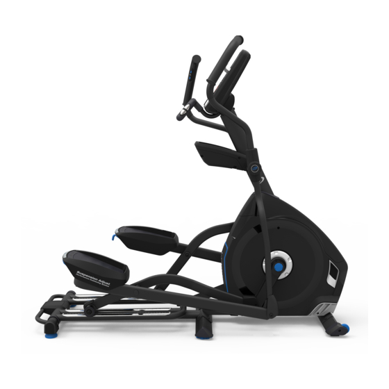
Nautilus
E618 Elliptical
™
Service Manual
Page Number
, OwnCode
, Google Play™, Under Armour
®
®
1
2
3
3
4
4
5
5
6
6
7
8
11
13
15
16
17
18
24
30
36
42
46
51
55
60
68
70
76
81
89
94
104
100
109
113
120
125
130
133
136
and MyFitnessPal
are trademarks of their respective owners.
®
®
Service Manual
8012457.101518.B
Advertisement
Table of Contents

Related Manuals for Nautilus E618


Summary of Contents for Nautilus E618
-
Page 1: Table Of Contents
Nautilus, Inc., www.NautilusInc.com, 5415 Centerpoint Parkway, Groveport, OH 43125 U.S.A. - Customer Service: North America (800) 605-3369, csnls@nautilus.com | outside U.S. www.nautilusinternational.com | © 2016 Nautilus, Inc. | Nautilus, the Nautilus logo, and Nautilus Trainer are trademarks owned by or licensed to Nautilus, Inc. Inc., which are registered or otherwise protected by common law in the United States and other countries. -
Page 2: Important Safety Instructions
Nautilus, Inc., www.NautilusInc.com, 5415 Centerpoint Parkway, Groveport, OH 43125 U.S.A. - Customer Service: North America (800) 605-3369, csnls@nautilus.com | outside U.S. www.nautilusinternational.com | © 2016 Nautilus, Inc. | Nautilus, the Nautilus logo, and Nautilus Trainer are trademarks owned by or licensed to Nautilus, Inc. Inc., which are registered or otherwise protected by common law in the United States and other countries. -
Page 3: Safety Warning Labels And Serial Number
SAFETY WARNING LABELS AND SERIAL NUMBER WARNING! • Injury or death is possible if caution is not used while using this machine. • Keep children and pets away. • Read and follow all warnings on this machine. • Refer to the Owner’s Manual for additional warnings and safety information. -
Page 4: Grounding Instructions
Grounding Instructions This product must be grounded. If it should malfunction or break down, grounding provides a path of least resistance for electric current to reduce the risk of electric shock. This product is equipped with a cord having an equipment-grounding conductor and a grounding plug. -
Page 5: Maintenance
Worn or damaged components must be repaired or replaced immediately. Only manufacturer supplied components can be used to maintain and repair the equipment. If at any time the Warning labels become loose, unreadable or dislodged, contact Nautilus Customer Service for replacement labels. -
Page 6: Moving The Machine
Moving the Machine The machine may be moved by one or more persons depending on their physical abilities and capacities. Make sure that you and others are all physically fit and able to move the machine safely. Remove the power cord. Use the Transport Handle to carefully lift the machine onto the transport rollers. -
Page 7: Connectivity
® your results and share with friends and family. 1. Download the free Software App, named Nautilus Trainer™. The software app is available on the App Store and Google Play™. Note: For a complete list of supported devices, review the software app on the App Store or Google Play™. -
Page 8: Troubleshooting
TROUBLESHOOTING Condition/Problem Things to Check Solution No display/partial display/ Check electrical (wall) Make sure unit is plugged into a functioning wall outlet. unit will not turn on outlet Check connection at front Connection should be secure and undamaged. Replace of unit adapter or connection at unit if either are damaged. - Page 9 Condition/Problem Things to Check Solution Resistance does not Check Console Check for visual sign that Console is damaged. Replace Con- change (machine turns on sole if damaged. and operates) Check data cable integrity All wires in cable should be intact. If any are visibly crimped or cut, replace cable.
- Page 10 Consult your device to be sure that the Bluetooth wireless ® ® feature has been enabled on it. Fitness App Review Specifications of Fitness App and confirm your device is compatible. Contact appsupport@nautilus.com (if inside US/Canada) or your local distributor (if outside US/Canada) for further assistance.
-
Page 11: Console Service Mode
Condition/Problem Things to Check Solution Workout results not post- Sync accounts From the Menu icon on the Nautilus Trainer™ App, select the ing from Nautilus Trainer Sync to MyFitnessPal or Under Armour Connected Fitness. ™ ® ® to MyFitnessPal / Under ®... - Page 12 DEBUG TERMINAL – Not used. c. MOVE LIFT – (E618 elliptical only) Used to adjust a new lift motor. The Console displays “UP MX DN MN RT CAL”: Up arrow will move the lift motor to the maximum position; Down arrow will move the lift motor to the minimum position;...
-
Page 13: Maintenance Parts
Maintenance Parts... - Page 14 Console Shroud, Left GG Drive Belt Heart Rate (HR) Cable Handlebar Shroud, Outer Drive Pulley Handlebar, Static Handlebar Shroud, Inner Speed Sensor Magnet Data (I/O) Cable, Upper Data (I/O) Cable, Lower RPM (Speed) Sensor Arm Pivot Rod Incline Adjuster Assembly Flywheel Console Mast Frame Assembly...
-
Page 15: Electrical Layout
Electrical Layout NLS E618 Wiring Diagram Console Incline Resistance Contact Down Down Heart Rate (CHR) sensor Lift motor wire, 5Pin HR cable, 4Pin I/O (Data) cable, 12Pin Lift motor potentiometer cable, 3Pin Servo control cable, 9VDC, 2Pin CCW CW Lift motor... -
Page 16: Motor Control Board (Mcb)
Motor Control Board (MCB) Power Inlet (line) Power Inlet (neutral) Lift motor common (neutral) Lift Motor CW (line) Lift Motor position Lift Motor CCW (line) potentiometer Servo Control Lift Motor Wire (to Console) -
Page 17: Replacement Procedure Skill Level
REPLACEMENT PROCEDURE SKILL LEVEL Level I : Low - very little mechanical knowledge or exposure. Level II : Intermediate - some experience with mechanical procedures Level III : Advanced - knowledgeable about mechanical procedures To reduce the risk of electrical shock or unsupervised usage of the equipment, always unplug the power cord from the wall outlet and wait 5 minutes before cleaning, maintaining or repairing this machine. -
Page 18: Set The Brake Tension (Calibration)
Nautilus, Inc., www.NautilusInc.com, 5415 Centerpoint Parkway, Groveport, OH 43125 U.S.A. - Customer Service: North America (800) 605-3369, csnls@nautilus.com | outside U.S. www.nautilusinternational.com | © 2016 Nautilus, Inc. | Nautilus and the Nautilus logo are trademarks owned by or licensed to Nautilus, Inc. Inc., which are registered or otherwise protected by common law in the United States and other countries. - Page 19 1. Turn the power on to the machine. 2. Set the resistance level to the maximum setting on the Console. 3. Turn the power switch to off and disconnect all power and allow to sit for 5 minutes. To reduce the risk of electrical shock or unsupervised usage of the equipment, always unplug the power cord from the wall outlet and wait 5 minutes before cleaning, maintaining or repairing this machine.
- Page 20 6. Disconnect the indicated Cable (with arrow) from the Upper Handlebar that goes into the Console Mast. 7. Using a 6mm hex wrench and a 13mm wrench, remove the indicated hardware (by oval) from the Arm Pivot Rod. Remove the hardware and the Upper and Lower Handlebar Arms. Set them safely aside for reassembly. 8. Using a 6mm hex wrench, loosen and remove the indicated hardware from the Left Crank Arm and Leg, and set it safely aside for reassembly.
- Page 21 10. Using a 14mm socket and ratchet, remove the Lock Nut from the Left Crank Arm. 11. Thread the Crank Puller into the Crank Arm. When the Crank Puller is in the correct position, only 1-2 threads on the outer portion (CP2) of the Crank Puller should show.
- Page 22 15. Using a #2 Phillips screwdriver, remove the 3 indicated screws (with arrows) that secure the Right Shroud. Remove the bottom screws first, and then the top screw. Slowly remove the Right Shroud. Motorized Lift Cover 16. Insert 2.5” x 10” cardboard between the Flywheel and the Brake Magnet Brake Magnet, and tape the cardboard to the Brake Magnet. Note: Be sure the cardboard covers all of the Brake Magnet. Flywheel Flywheel Brake Magnet...
- Page 23 17. To adjust the Brake tension, loosen the 2 hex head bolts and move the Servo Motor assembly until the closest point on the Brake Magnet is within 3.0mm (1/8”) of the Flywheel. Tighten the bolts. Brake Magnet Note: If the cardboard is not 3mm (1/8”) thick, you can use the pages of a paperback book to measure the gap. Approximately 36 Flywheel pages (sheets) = 3mm.
-
Page 24: Adjust The Belt Tension
Nautilus, Inc., www.NautilusInc.com, 5415 Centerpoint Parkway, Groveport, OH 43125 U.S.A. - Customer Service: North America (800) 605-3369, csnls@nautilus.com | outside U.S. www.nautilusinternational.com | © 2016 Nautilus, Inc. | Nautilus and the Nautilus logo are trademarks owned by or licensed to Nautilus, Inc. Inc., which are registered or otherwise protected by common law in the United States and other countries. - Page 25 To reduce the risk of electrical shock or unsupervised usage of the equipment, always unplug the power cord from the wall outlet and wait 5 minutes before cleaning, maintaining or repairing this machine. Place the power cord in a secure location.
- Page 26 5. Using a 6mm hex key, loosen and remove the indicated hardware from the Left Crank Arm and Leg, and set it safely aside for reassembly. Remove the left Leg and Pedal together from the Rail Assembly and set them safely aside for reassembly. NOTICE: This step may require two people. Crank Arm 9.
- Page 27 11. Thread the Crank Puller into the Crank Arm. When the Crank Puller is in the correct position, only 1-2 threads on the outer portion (CP2) of the Crank Puller should show. Note: B e sure the end of the Bolt (CP1) of the Crank Puller is flush with the Nut (CP2) as shown, before use. 12.
- Page 28 Note: Your machine may not match the image. For reference only. 15. To test the Drive Belt tension: • Push the Drive Belt downward at the midpoint (M) between the pulleys and measure the distance. The Drive Belt should have only 0.25”...
- Page 29 19. Installation is the reverse procedure. Put the Left Shroud in position first to align the screws for the Right Shroud. Install the top screws first. NOTICE: This step may require two people. Be sure not to crimp any cables. Note: Self-tapping screws attach the Shrouds to the Frame. Be sure the tabs in the Motorized Lift Cover snap into the Side Shrouds. Installation does not require the use of the crank puller.
-
Page 30: Replace The Tensioner Assembly
Nautilus, Inc., www.NautilusInc.com, 5415 Centerpoint Parkway, Groveport, OH 43125 U.S.A. - Customer Service: North America (800) 605-3369, csnls@nautilus.com | outside U.S. www.nautilusinternational.com | © 2016 Nautilus, Inc. | Nautilus and the Nautilus logo are trademarks owned by or licensed to Nautilus, Inc. Inc., which are registered or otherwise protected by common law in the United States and other countries. - Page 31 To reduce the risk of electrical shock or unsupervised usage of the equipment, always unplug the power cord from the wall outlet and wait 5 minutes before cleaning, maintaining or repairing this machine. Place the power cord in a secure location.
- Page 32 5. Using a 6mm hex key, loosen and remove the indicated hardware from the Left Crank Arm and Leg, and set it safely aside for reassembly. Remove the left Leg and Pedal together from the Rail Assembly and set them safely aside for reassembly. NOTICE: This step may require two people. Crank Arm 6.
- Page 33 8. Thread the Crank Puller into the Crank Arm. When the Crank Puller is in the correct position, only 1-2 threads on the outer portion (CP2) of the Crank Puller should show. Note: B e sure the end of the Bolt (CP1) of the Crank Puller is flush with the Nut (CP2) as shown, before use. 9.
- Page 34 12. Measure or mark on a piece of scrap paper the length from the end of the Tensioner Bolt to the outer Tensioner Nut. This will assist with re- assembly. 13. Using a 10mm wrench, loosen and remove the outer Tensioner Nut so the Tension Bolt can be released from the Tensioner Bracket.
- Page 35 18. To adjust the Tensioner Nuts on the Tensioner Bracket, use a 10mm open end wrench to hold the Tensioner Bolt steady and turn the nuts with a second 10mm open end wrench. 19. When the tension is correct, tighten the nuts against the Tensioner Bracket to hold the bolt and the Tensioner Assembly Tensioner Bracket in position.
-
Page 36: Replace The Brake Assembly
Nautilus, Inc., www.NautilusInc.com, 5415 Centerpoint Parkway, Groveport, OH 43125 U.S.A. - Customer Service: North America (800) 605-3369, csnls@nautilus.com | outside U.S. www.nautilusinternational.com | © 2016 Nautilus, Inc. | Nautilus and the Nautilus logo are trademarks owned by or licensed to Nautilus, Inc. Inc., which are registered or otherwise protected by common law in the United States and other countries. - Page 37 To reduce the risk of electrical shock or unsupervised usage of the equipment, always unplug the power cord from the wall outlet and wait 5 minutes before cleaning, maintaining or repairing this machine. Place the power cord in a secure location.
- Page 38 5. Using a 6mm hex key, loosen and remove the indicated hardware from the Left Crank Arm and Leg, and set it safely aside for reassembly. Remove the left Leg and Pedal together from the Rail Assembly and set them safely aside for reassembly. NOTICE: This step may require two people. Crank Arm 6.
- Page 39 8. Thread the Crank Puller into the Crank Arm. When the Crank Puller is in the correct position, only 1-2 threads on the outer portion (CP2) of the Crank Puller should show. Note: B e sure the end of the Bolt (CP1) of the Crank Puller is flush with the Nut (CP2) as shown, before use. 9.
- Page 40 13. Insert 2.5” x 10” cardboard between the Flywheel and the Brake Magnet, and tape the cardboard to the Brake Magnet. Brake Magnet Note: Be sure the cardboard covers all of the Brake Magnet. Flywheel Brake Magnet Hardware Brake Magnet Hardware Flywheel Brake Magnet 14. Use pliers to unhook the Tension Spring from the Main Frame. Pull back and release the Magnet Arm enough to disengage it from the Motor Pulley Shaft.
- Page 41 18. Before fully attaching the Shrouds, power up the machine to verify that the Magnet Arm can move freely, and that the Brake Magnet and Flywheel do not touch at the maximum resistance level. Machine is on. Current is active. There is risk of electrical shock. Be sure to keep fingers clear of all pinch hazards when you change the resistance level.
-
Page 42: Replace The Console
Nautilus, Inc., www.NautilusInc.com, 5415 Centerpoint Parkway, Groveport, OH 43125 U.S.A. - Customer Service: North America (800) 605-3369, csnls@nautilus.com | outside U.S. www.nautilusinternational.com | © 2016 Nautilus, Inc. | Nautilus and the Nautilus logo are trademarks owned by or licensed to Nautilus, Inc. Inc., which are registered or otherwise protected by common law in the United States and other countries. - Page 43 To reduce the risk of electrical shock or unsupervised usage of the equipment, always unplug the power cord from the wall outlet and the machine and wait 5 minutes before cleaning, maintaining or repairing the machine. Place the power cord in a secure location.
- Page 44 3. Gently lift and remove the Console/Static Handlebar Assembly from the Console Mast and disconnect the four cables (the Input/Output, Lift Motor, Resistance Control, and Incline Control Cables) that come from the back of the Console. Note: Do not let the Cables fall down inside the Console Mast. If neces- sary, use a rubber band or wire tie to secure them.
- Page 45 7. Plug the machine in and turn the power on to the machine. Initial Setup During the first power-up, the Console should be setup with the date, time and your preferred measurement units. 8. Date: Push the Increase/Decrease buttons to adjust the currently active value (flashing). Push the Left/Right buttons to change which segment is the currently active value (month / day / year). 9. Push OK to set. 10. Time: Push the Increase/Decrease buttons to adjust the currently active value (flashing). Push the Left/Right buttons to change which segment is the currently active value (hour / minute / AM or PM). 11.
-
Page 46: Replace The Console Mast And Water Bottle Holder
Nautilus, Inc., www.NautilusInc.com, 5415 Centerpoint Parkway, Groveport, OH 43125 U.S.A. - Customer Service: North America (800) 605-3369, csnls@nautilus.com | outside U.S. www.nautilusinternational.com | © 2016 Nautilus, Inc. | Nautilus and the Nautilus logo are trademarks owned by or licensed to Nautilus, Inc. Inc., which are registered or otherwise protected by common law in the United States and other countries. - Page 47 To reduce the risk of electrical shock or unsupervised usage of the equipment, always unplug the power cord from the wall outlet and wait 5 minutes before cleaning, maintaining or repairing this machine. Place the power cord in a secure location.
- Page 48 3. Gently lift and remove the Console/Static Handlebar Assembly from the Console Mast and disconnect the four cables (the Input/Output, Lift Motor, Resistance Control, and Incline Control Cables) that come from the back of the Console. Note: Do not let the Cables fall down inside the Console Mast. If neces- sary, use a rubber band or wire tie to secure them.
- Page 49 6. Disconnect the indicated Cable (with arrow) from the Upper Handlebar that goes into the Console Mast. 7. Using a 6mm hex wrench and a 13mm wrench, remove the hardware from the Lower Handlebar Arm and the Arm Pivot Rod. The hardware on both ends of the Arm Pivot Rod will need to be held to remove it. 8.
- Page 50 14. Installation is the reverse procedure. NOTICE: Do not crimp the cables. Do not allow the cables to fall down into the Console Mast. 15. Inspect your machine to ensure that all hardware is tight and compo- nents are properly assembled. Do not use until the machine has been fully assembled and inspected for correct performance in accordance with the Owner’s Manual.
-
Page 51: Replace The Crank Arms
Nautilus, Inc., www.NautilusInc.com, 5415 Centerpoint Parkway, Groveport, OH 43125 U.S.A. - Customer Service: North America (800) 605-3369, csnls@nautilus.com | outside U.S. www.nautilusinternational.com | © 2016 Nautilus, Inc. | Nautilus and the Nautilus logo are trademarks owned by or licensed to Nautilus, Inc. Inc., which are registered or otherwise protected by common law in the United States and other countries. - Page 52 To reduce the risk of electrical shock or unsupervised usage of the equipment, always unplug the power cord from the wall outlet and wait 5 minutes before cleaning, maintaining or repairing this machine. Place the power cord in a secure location.
- Page 53 5. Using a 6mm hex key, loosen and remove the indicated hardware from the Crank Arm and Leg, and set it safely aside for reassembly. On each side of the machine, remove the Leg and Pedal together from the Rail Assembly and set them safely aside for reassembly. NOTICE: This step may require two people. Crank Arm 6.
- Page 54 8. Thread the Crank Puller into the Crank Arm. When the Crank Puller is in the correct position, only 1-2 threads on the outer portion (CP2) of the Crank Puller should show. Note: B e sure the end of the Bolt (CP1) of the Crank Puller is flush with the Nut (CP2) as shown, before use. 9.
-
Page 55: Replace The Input/Output (I/O) Cable In The Console Mast
Nautilus, Inc., www.NautilusInc.com, 5415 Centerpoint Parkway, Groveport, OH 43125 U.S.A. - Customer Service: North America (800) 605-3369, csnls@nautilus.com | outside U.S. www.nautilusinternational.com | © 2016 Nautilus, Inc. | Nautilus and the Nautilus logo are trademarks owned by or licensed to Nautilus, Inc. Inc., which are registered or otherwise protected by common law in the United States and other countries. - Page 56 To reduce the risk of electrical shock or unsupervised usage of the equipment, always unplug the power cord from the wall outlet and wait 5 minutes before cleaning, maintaining or repairing this machine. Place the power cord in a secure location.
- Page 57 3. Gently lift and remove the Console/Static Handlebar Assembly from the Console Mast and disconnect the four cables (the Input/Output, Lift Motor, Resistance Control, and Incline Control Cables) that come from the back of the Console. Note: Do not let the Cables fall down inside the Console Mast. If neces- sary, use a rubber band or wire tie to secure them.
- Page 58 6. Disconnect the indicated Cable (with arrow) from the Upper Handlebar that goes into the Console Mast. 7. Using a 6mm hex wrench and a 13mm wrench, remove the hardware from the Lower Handlebar Arm and the Arm Pivot Rod. The hardware on both ends of the Arm Pivot Rod will need to be held to remove it. 8.
- Page 59 13. Untie the string from the old Input/Output (I/O) Cable and discard the old cable. 14. Tie the end of the string at the base of the Cable Mast to one end of the replacement Input/Output (I/O) Cable. Hold the other end of the string and carefully pull the new Input/Output (I/O) Cable through the Cable Mast.
-
Page 60: Replace The Drive Belt And Flywheel
Nautilus, Inc., www.NautilusInc.com, 5415 Centerpoint Parkway, Groveport, OH 43125 U.S.A. - Customer Service: North America (800) 605-3369, csnls@nautilus.com | outside U.S. www.nautilusinternational.com | © 2016 Nautilus, Inc. | Nautilus and the Nautilus logo are trademarks owned by or licensed to Nautilus, Inc. Inc., which are registered or otherwise protected by common law in the United States and other countries. - Page 61 To reduce the risk of electrical shock or unsupervised usage of the equipment, always unplug the power cord from the wall outlet and wait 5 minutes before cleaning, maintaining or repairing this machine. Place the power cord in a secure location.
- Page 62 5. Using a 6mm hex key, loosen and remove the indicated hardware from the Left Crank Arm and Leg, and set it safely aside for reassembly. Remove the left Leg and Pedal together from the Rail Assembly and set them safely aside for reassembly. NOTICE: This step may require two people. Crank Arm 6.
- Page 63 8. Thread the Crank Puller into the Crank Arm. When the Crank Puller is in the correct position, only 1-2 threads on the outer portion (CP2) of the Crank Puller should show. Note: B e sure the end of the Bolt (CP1) of the Crank Puller is flush with the Nut (CP2) as shown, before use. 9.
- Page 64 12. Insert 2.5” x 10” cardboard between the Flywheel and the Brake Magnet, and tape the cardboard to the Brake Magnet. Flywheel Note: Be sure the cardboard covers all of the Brake Magnet. Brake Magnet 13. Measure or mark a piece of scrap paper the length from the Drive Belt end of the Tensioner Bolt to the outer Tensioner Nut.
- Page 65 17. To remove the indicated hardware (by oval) from the Flywheel, use a 17mm open end wrench to hold the nut on one side steady and remove the nut on the opposite side with the 17mm socket and wrench. Set the hardware safely aside. Flywheel 18.
- Page 66 Note: Your machine may not match the image. For reference only. 24. To test the Drive Belt tension: • Push the Drive Belt downward at the midpoint (M) between the pulleys and measure the distance. The Drive Belt should have only 0.25” (0.64 cm) of give. •...
- Page 67 28. To tighten the Flywheel hardware use the 17mm open end wrench to hold the nut on one side steady and tighten the nut on the opposite side with the 17mm socket and wrench. Flywheel 29. Before fully attaching the Shrouds, power up the machine to verify that the Magnet Arm can move freely, and that the Brake Magnet and Flywheel do not touch at the maximum resistance level.
-
Page 68: Replace The Front Stabilizer
Nautilus, Inc., www.NautilusInc.com, 5415 Centerpoint Parkway, Groveport, OH 43125 U.S.A. - Customer Service: North America (800) 605-3369, csnls@nautilus.com | outside U.S. www.nautilusinternational.com | © 2016 Nautilus, Inc. | Nautilus and the Nautilus logo are trademarks owned by or licensed to Nautilus, Inc. Inc., which are registered or otherwise protected by common law in the United States and other countries. - Page 69 To reduce the risk of electrical shock or unsupervised usage of the equipment, always unplug the power cord from the wall outlet and wait 5 minutes before cleaning, maintaining or repairing this machine. Place the power cord in a secure location.
-
Page 70: Replace The Incline Adjuster Assembly
Nautilus, Inc., www.NautilusInc.com, 5415 Centerpoint Parkway, Groveport, OH 43125 U.S.A. - Customer Service: North America (800) 605-3369, csnls@nautilus.com | outside U.S. www.nautilusinternational.com | © 2016 Nautilus, Inc. | Nautilus and the Nautilus logo are trademarks owned by or licensed to Nautilus, Inc. Inc., which are registered or otherwise protected by common law in the United States and other countries. - Page 71 To reduce the risk of electrical shock or unsupervised usage of the equipment, always unplug the power cord from the wall outlet and wait 5 minutes before cleaning, maintaining or repairing this machine. Place the power cord in a secure location.
- Page 72 5. Using a 6mm hex key, loosen and remove the indicated hardware from the Crank Arm and Leg, and set it safely aside for reassembly. On each side of the machine, remove the Leg and Pedal together from the Rail Assembly and set them safely aside for reassembly. NOTICE: This step may require two people. Crank Arm 6.
- Page 73 8. Using a 14mm socket and ratchet, remove the Lock Nut from the Crank Arm. 9. Thread the Crank Puller into the Crank Arm. When the Crank Puller is in the correct position, only 1-2 threads on the outer portion (CP2) of the Crank Puller should show.
- Page 74 14. Using a #2 Phillips screwdriver, remove the 3 indicated screws (with arrows) that secure the Right Shroud. Remove the bottom screws first, and then the top screw. Slowly remove the Right Shroud. Motorized Lift Cover 15. Using the 18mm open end wrench, remove the indicated bolts (with an oval) that attach the Incline Adjuster bracket to the Lift Motor Assembly. This will allow the Incline Adjuster Assembly to pivot.
- Page 75 19. Installation is the reverse procedure. Note: Be sure the number of threads showing on the Lift Motor shaft between the Collar Nut and the Lift Motor base is the same as the number recorded in Step 16. If the number is different, turn the collar nut until the thread count is the same.
-
Page 76: Replace The Remote Incline Or Resistance Cables To Handlebars
Nautilus, Inc., www.NautilusInc.com, 5415 Centerpoint Parkway, Groveport, OH 43125 U.S.A. - Customer Service: North America (800) 605-3369, csnls@nautilus.com | outside U.S. www.nautilusinternational.com | © 2016 Nautilus, Inc. | Nautilus and the Nautilus logo are trademarks owned by or licensed to Nautilus, Inc. Inc., which are registered or otherwise protected by common law in the United States and other countries. - Page 77 To reduce the risk of electrical shock or unsupervised usage of the equipment, always unplug the power cord from the wall outlet and wait 5 minutes before cleaning, maintaining or repairing this machine. Place the power cord in a secure location.
- Page 78 3. Gently lift and remove the Console/Static Handlebar Assembly from the Console Mast and disconnect the four cables (the Input/Output, Lift Motor, Resistance Control, and Incline Control Cables) that come from the back of the Console. Note: Do not let the Cables fall down inside the Console Mast. If neces- sary, use a rubber band or wire tie to secure them.
- Page 79 Note: The Remote Incline Cable is on the left side of the machine, and the Remote Resistance Cable on the right. The following photos show the Remote Incline Cable being replaced. If replacing the Remote Resistance Cable, perform the same steps but on the right side of the machine. 6.
- Page 80 13. Tie the end of the string out of the side of the Cable Mast to the upper end of the replacement Remote Incline Cable. Hold the other end of the string and carefully pull the new Remote Incline Cable through the Cable Mast.
-
Page 81: Replace The Lift Motor
Nautilus, Inc., www.NautilusInc.com, 5415 Centerpoint Parkway, Groveport, OH 43125 U.S.A. - Customer Service: North America (800) 605-3369, csnls@nautilus.com | outside U.S. www.nautilusinternational.com | © 2016 Nautilus, Inc. | Nautilus and the Nautilus logo are trademarks owned by or licensed to Nautilus, Inc. Inc., which are registered or otherwise protected by common law in the United States and other countries. - Page 82 To reduce the risk of electrical shock or unsupervised usage of the equipment, always unplug the power cord from the wall outlet and wait 5 minutes before cleaning, maintaining or repairing this machine. Place the power cord in a secure location.
- Page 83 5. Using a 6mm hex key, loosen and remove the indicated hardware from the Crank Arm and Leg, and set it safely aside for reassembly. On each side of the machine, remove the Leg and Pedal together from the Rail Assembly and set them safely aside for reassembly. NOTICE: This step may require two people. Crank Arm 6.
- Page 84 8. Using a 14mm socket and ratchet, remove the Lock Nut from the Crank Arm. 9. Thread the Crank Puller into the Crank Arm. When the Crank Puller is in the correct position, only 1-2 threads on the outer portion (CP2) of the Crank Puller should show.
- Page 85 14. Using a #2 Phillips screwdriver, remove the 3 indicated screws (with arrows) that secure the Right Shroud. Remove the bottom screws first, and then the top screw. Slowly remove the Right Shroud. Motorized Lift Cover 15. Using the 18mm open end wrench, remove the indicated bolts (with an oval) that attach the Incline Adjuster bracket to the Lift Motor Assembly. This will allow the Incline Adjuster Assembly to pivot.
- Page 86 19. Using a #2 Phillips screwdriver, remove the top screw to free the Lift Motor ground wire. Hand tighten the top screw to hold the MCB Assembly in position on the Frame until reassembly. Lift motor ground wire Assembly 20. Disconnect the Lift Motor cable from the Motor Control Board after noting the connector locations.
- Page 87 21. Using the 18mm socket and wrench and 18mm open end wrench, loosen and remove the indicated hex head bolts (by arrow) that attach the Lift Motor Shaft Incline Adjuster Assembly to the Lift Motor shaft. Set the bolts aside for reassembly. Incline Adjuster Assembly Lift Motor Assembly 22. Remove the indicated hardware (by arrow) that attaches the Lift Motor Assembly to the Frame.
- Page 88 30. Push the Down arrow button 2 times to go to the MOVE LIFT option and push OK to enter the lift options menu. 31. The console displays the UP MX DN MN RT CAL prompt. Push the Down arrow so that the Lift Motor turns to the lower limit. 32.
-
Page 89: Replace The Lift Motor Wire In The Console Mast
Nautilus, Inc., www.NautilusInc.com, 5415 Centerpoint Parkway, Groveport, OH 43125 U.S.A. - Customer Service: North America (800) 605-3369, csnls@nautilus.com | outside U.S. www.nautilusinternational.com | © 2016 Nautilus, Inc. | Nautilus and the Nautilus logo are trademarks owned by or licensed to Nautilus, Inc. Inc., which are registered or otherwise protected by common law in the United States and other countries. - Page 90 To reduce the risk of electrical shock or unsupervised usage of the equipment, always unplug the power cord from the wall outlet and wait 5 minutes before cleaning, maintaining or repairing this machine. Place the power cord in a secure location.
- Page 91 3. Gently lift and remove the Console/Static Handlebar Assembly from the Console Mast and disconnect the four cables (the Input/Output, Lift Motor, Resistance Control, and Incline Control Cables) that come from the back of the Console. Note: Do not let the Cables fall down inside the Console Mast. If neces- sary, use a rubber band or wire tie to secure them.
- Page 92 6. Disconnect the indicated Cable (with arrow) from the Upper Handlebar that goes into the Console Mast. 7. Using a 6mm hex wrench and a 13mm wrench, remove the hardware from the Lower Handlebar Arm and the Arm Pivot Rod. The hardware on both ends of the Arm Pivot Rod will need to be held to remove it. 8.
- Page 93 13. Untie the string from the old Lift Motor Wire and discard the old cable. 14. Tie the end of the string at the base of the Cable Mast to one end of the replacement Lift Motor Wire. Hold the other end of the string and carefully pull the new Lift Motor Wire through the Cable Mast.
-
Page 94: Replace The Motor Control Board (Mcb)
Nautilus, Inc., www.NautilusInc.com, 5415 Centerpoint Parkway, Groveport, OH 43125 U.S.A. - Customer Service: North America (800) 605-3369, csnls@nautilus.com | outside U.S. www.nautilusinternational.com | © 2016 Nautilus, Inc. | Nautilus and the Nautilus logo are trademarks owned by or licensed to Nautilus, Inc. Inc., which are registered or otherwise protected by common law in the United States and other countries. - Page 95 To reduce the risk of electrical shock or unsupervised usage of the equipment, always unplug the power cord from the wall outlet and wait 5 minutes before cleaning, maintaining or repairing this machine. Place the power cord in a secure location.
- Page 96 5. Using a 6mm hex key, loosen and remove the indicated hardware from the Left Crank Arm and Leg, and set it safely aside for reassembly. Remove the left Leg and Pedal together from the Rail Assembly and set them safely aside for reassembly. NOTICE: This step may require two people. Crank Arm 6.
- Page 97 8. Thread the Crank Puller into the Crank Arm. When the Crank Puller is in the correct position, only 1-2 threads on the outer portion (CP2) of the Crank Puller should show. Note: B e sure the end of the Bolt (CP1) of the Crank Puller is flush with the Nut (CP2) as shown, before use. 9.
- Page 98 12. Observe the cable routing from the Motor Control Board (MCB) Assembly on your machine. Input/Output (I/O) Lift Motor Cable Cable • Power Inlet Cable (Power switch to MCB) • Lift Motor Cable, Lower (Lift Motor to MCB) • Lift Motor Wire, Upper (MCB to Console) •...
- Page 99 Power Inlet (line) Power Inlet (neutral) Lift motor common (neutral) Lift Motor CW (line) Lift Motor position Lift Motor CCW (line) potentiometer 18. Reassembly is the reverse procedure. Secure the cables Servo Control with zipties. Lift Motor Wire (to Console) Put the Left Shroud in position first to align the screws for the Right Shroud. Install the top screws first.
- Page 100 NLS E618 Wiring Diagram Console Incline Resistance Contact Down Down Heart Rate (CHR) sensor Lift motor wire, 5Pin HR cable, 4Pin I/O (Data) cable, 12Pin Lift motor potentiometer cable, 3Pin Servo control cable, 9VDC, 2Pin CCW CW Lift motor Power inlet...
-
Page 101: Replace The Pedals And Legs
Nautilus, Inc., www.NautilusInc.com, 5415 Centerpoint Parkway, Groveport, OH 43125 U.S.A. - Customer Service: North America (800) 605-3369, csnls@nautilus.com | outside U.S. www.nautilusinternational.com | © 2016 Nautilus, Inc. | Nautilus and the Nautilus logo are trademarks owned by or licensed to Nautilus, Inc. Inc., which are registered or otherwise protected by common law in the United States and other countries. - Page 102 To reduce the risk of electrical shock or unsupervised usage of the equipment, always unplug the power cord from the wall outlet and wait 5 minutes before cleaning, maintaining or repairing this machine. Place the power cord in a secure location.
- Page 103 3. Remove the Pedal. 4. Using a 6mm hex wrench, remove the indicated hardware from the Crank Arm and Leg. 5. Remove the old Leg and replace with the new one. Crank Arm 6. Installation is the reverse procedure. 7. Discard the old parts. 8. Inspect your machine to ensure that all hardware is tight and components are properly assembled.
-
Page 104: Replace The Power Switch Assembly
Nautilus, Inc., www.NautilusInc.com, 5415 Centerpoint Parkway, Groveport, OH 43125 U.S.A. - Customer Service: North America (800) 605-3369, csnls@nautilus.com | outside U.S. www.nautilusinternational.com | © 2016 Nautilus, Inc. | Nautilus and the Nautilus logo are trademarks owned by or licensed to Nautilus, Inc. Inc., which are registered or otherwise protected by common law in the United States and other countries. - Page 105 To reduce the risk of electrical shock or unsupervised usage of the equipment, always unplug the power cord from the wall outlet and wait 5 minutes before cleaning, maintaining or repairing this machine. Place the power cord in a secure location.
- Page 106 5. Using a 6mm hex key, loosen and remove the indicated hardware from the Crank Arm and Leg, and set it safely aside for reassembly. On each side of the machine, remove the Leg and Pedal together from the Rail Assembly and set them safely aside for reassembly. NOTICE: This step may require two people. Crank Arm 9.
- Page 107 11. Thread the Crank Puller into the Crank Arm. When the Crank Puller is in the correct position, only 1-2 threads on the outer portion (CP2) of the Crank Puller should show. Note: B e sure the end of the Bolt (CP1) of the Crank Puller is flush with the Nut (CP2) as shown, before use. 12.
- Page 108 16. Loosen and remove the two screws (one indicated with an arrow) that attach the back cover of the Power Switch assembly to the sides of the Frame. Remove the back cover. NOTICE: Do not crimp the cables. Power Switch Note: Your machine may not match the image.
-
Page 109: Replace The Rail Assembly
Nautilus, Inc., www.NautilusInc.com, 5415 Centerpoint Parkway, Groveport, OH 43125 U.S.A. - Customer Service: North America (800) 605-3369, csnls@nautilus.com | outside U.S. www.nautilusinternational.com | © 2016 Nautilus, Inc. | Nautilus and the Nautilus logo are trademarks owned by or licensed to Nautilus, Inc. Inc., which are registered or otherwise protected by common law in the United States and other countries. - Page 110 To reduce the risk of electrical shock or unsupervised usage of the equipment, always unplug the power cord from the wall outlet and wait 5 minutes before cleaning, maintaining or repairing this machine. Place the power cord in a secure location. 1.
- Page 111 4. Using a 6mm hex wrench and a 13mm wrench, remove the indicated hardware from the Lower Handlebar Arms and Pedals. Set the hardware safely aside for reassembly. Be aware that the Handlebar Arms will be loose and may pivot when the hardware is removed. This step may require two people. Note: To assist with reassembly, observe how the Pivot Sleeve engages flush with the Lower Handlebar Arm.
- Page 112 10. Place a static object (like a book or box) under the back of the main frame but not under the Rail Assembly. The static object (*) should not be compressible. 11. Using a 6mm hex wrench and a 13mm wrench, remove the 4 indicated screws that attach the Rail Assembly to the Frame Assembly. Be aware that the Frame Assembly may be unstable and slightly top heavy. 12.
-
Page 113: Replace The Servo Motor
Nautilus, Inc., www.NautilusInc.com, 5415 Centerpoint Parkway, Groveport, OH 43125 U.S.A. - Customer Service: North America (800) 605-3369, csnls@nautilus.com | outside U.S. www.nautilusinternational.com | © 2016 Nautilus, Inc. | Nautilus and the Nautilus logo are trademarks owned by or licensed to Nautilus, Inc. Inc., which are registered or otherwise protected by common law in the United States and other countries. - Page 114 1. With the machine turned on, set the resistance to the highest level. 2. Once the machine has reached the maximum resistance, turn off the machine and remove the power cord. To reduce the risk of electrical shock or unsuper- vised usage of the equipment, always unplug the power cord from the wall outlet and wait 5 minutes before cleaning, maintaining or repairing this machine.
- Page 115 5. Disconnect the indicated Cable (with arrow) from the Upper Handlebar that goes into the Console Mast. 6. Using a 6mm hex wrench and a 13mm wrench, remove the indicated hardware (by oval) from the Arm Pivot Rod. Remove the hardware and the Upper and Lower Handlebar Arms. Set them safely aside for reassembly. 7. Using a 6mm hex wrench, loosen and remove the indicated hardware Crank Arm from the Crank Arm and Leg, and set it safely aside for reassembly.
- Page 116 11. Using a 14mm socket and ratchet, remove the Lock Nut from the Crank Arm. 12. Thread the Crank Puller into the Crank Arm. When the Crank Puller is in the correct position, only 1-2 threads on the outer portion (CP2) of the Crank Puller should show.
- Page 117 17. Using a #2 Phillips screwdriver, remove the 3 indicated screws (with arrows) that secure the Right Shroud. Remove the bottom screws first, and then the top screw. Slowly remove the Right Shroud. Motorized Lift Cover 18. Measure and mark the position of the Servo Motor Bracket on the Main Frame. Brake Magnet 19. Insert 2.5” x 10” cardboard between the Brake Magnet and the Fly- Flywheel...
- Page 118 23. Use the pliers to unhook the Tension Spring from the Main Frame. Pull back and release the Brake Arm enough to disengage it from the Motor Pulley Shaft. Brake Magnet 24. Loosen and remove the two socket head bolts from the Servo Motor. Flywheel 25.
- Page 119 31. Installation is the reverse procedure. Note: Be sure the number of threads showing on the Lift Motor shaft between the Collar Nut and the Lift Motor base is the same as the number recorded in Step 16. If the number is different, turn the collar nut until the thread count is the same.
-
Page 120: Replace The Shrouds
Nautilus, Inc., www.NautilusInc.com, 5415 Centerpoint Parkway, Groveport, OH 43125 U.S.A. - Customer Service: North America (800) 605-3369, csnls@nautilus.com | outside U.S. www.nautilusinternational.com | © 2016 Nautilus, Inc. | Nautilus and the Nautilus logo are trademarks owned by or licensed to Nautilus, Inc. Inc., which are registered or otherwise protected by common law in the United States and other countries. - Page 121 To reduce the risk of electrical shock or unsupervised usage of the equipment, always unplug the power cord from the wall outlet and wait 5 minutes before cleaning, maintaining or repairing this machine. Place the power cord in a secure location.
- Page 122 5. Using a 6mm hex key, loosen and remove the indicated hardware from the Crank Arm and Leg, and set it safely aside for reassembly. On each side of the machine, remove the Leg and Pedal together from the Rail Assembly and set them safely aside for reassembly. NOTICE: This step may require two people. Crank Arm 6.
- Page 123 9. Using a 14mm socket and ratchet, remove the Lock Nut from the Crank Arm. 10. Thread the Crank Puller into the Crank Arm. When the Crank Puller is in the correct position, only 1-2 threads on the outer portion (CP2) of the Crank Puller should show.
- Page 124 14. Using a #2 Phillips screwdriver, remove the 3 indicated screws (with arrows) that secure the Right Shroud. Remove the bottom screws first, and then the top screw. Slowly remove the Right Shroud. Motorized Lift Cover If you are not replacing the Motorized Lift Cover—go to Step 18. If you are replacing the Motorized Lift Cover — remove the indicated hardware (by oval) that attaches the Incline Adjuster Assembly to the Rail Assembly, using a 6mm hex wrench and a 13mm wrench.
-
Page 125: Replace The Speed Sensor
Nautilus, Inc., www.NautilusInc.com, 5415 Centerpoint Parkway, Groveport, OH 43125 U.S.A. - Customer Service: North America (800) 605-3369, csnls@nautilus.com | outside U.S. www.nautilusinternational.com | © 2016 Nautilus, Inc. | Nautilus and the Nautilus logo are trademarks owned by or licensed to Nautilus, Inc. Inc., which are registered or otherwise protected by common law in the United States and other countries. - Page 126 To reduce the risk of electrical shock or unsupervised usage of the equipment, always unplug the power cord from the wall outlet and wait 5 minutes before cleaning, maintaining or repairing this machine. Place the power cord in a secure location.
- Page 127 5. Using a 6mm hex wrench, loosen and remove the indicated hardware from the Left Crank Arm and Leg, and set it safely aside for reassembly. Remove the left Leg and Pedal together from the Rail Assembly and set them safely aside for reassembly. NOTICE: This step may require two people. Crank Arm 6.
- Page 128 8. Thread the Crank Puller into the Crank Arm. When the Crank Puller is in the correct position, only 1-2 threads on the outer portion (CP2) of the Crank Puller should show. Note: B e sure the end of the Bolt (CP1) of the Crank Puller is flush with the Nut (CP2) as shown, before use. 9.
- Page 129 13. Disconnect the Speed Sensor Cable from the Servo Motor wiring harness. NOTICE: Do not touch the Potentiometer. Do not crimp any cables. Speed Sensor Cable Connection Servo Motor Potentiometer 14. Observe the cable routing from the Speed Sensor Magnet to the Servo Motor wiring harness.
-
Page 130: Replace The Static Handlebar
Nautilus, Inc., www.NautilusInc.com, 5415 Centerpoint Parkway, Groveport, OH 43125 U.S.A. - Customer Service: North America (800) 605-3369, csnls@nautilus.com | outside U.S. www.nautilusinternational.com | © 2016 Nautilus, Inc. | Nautilus and the Nautilus logo are trademarks owned by or licensed to Nautilus, Inc. Inc., which are registered or otherwise protected by common law in the United States and other countries. - Page 131 To reduce the risk of electrical shock or unsupervised usage of the equipment, always unplug the power cord from the wall outlet and the machine and wait 5 minutes before cleaning, maintaining or repairing the machine. Place the power cord in a secure location.
- Page 132 3. Gently lift and remove the Console/Static Handlebar Assembly from the Console Mast and disconnect the four cables (the Input/Output, Lift Motor, Resistance Control, and Incline Control Cables) that come from the back of the Console. Note: Do not let the Cables fall down inside the Console Mast. If neces- sary, use a rubber band or wire tie to secure them.
-
Page 133: Replace The Upper And Lower Handlebar Arms
Nautilus, Inc., www.NautilusInc.com, 5415 Centerpoint Parkway, Groveport, OH 43125 U.S.A. - Customer Service: North America (800) 605-3369, csnls@nautilus.com | outside U.S. www.nautilusinternational.com | © 2016 Nautilus, Inc. | Nautilus and the Nautilus logo are trademarks owned by or licensed to Nautilus, Inc. Inc., which are registered or otherwise protected by common law in the United States and other countries. - Page 134 To reduce the risk of electrical shock or unsupervised usage of the equipment, always unplug the power cord from the wall outlet and wait 5 minutes before cleaning, maintaining or repairing this machine. Place the power cord in a secure location.
- Page 135 5. Using a 6mm hex wrench and a 13mm wrench, remove the indicated hardware from the Lower Handlebar Arms and Pedal. Note: To assist with reassembly, observe how the Pivot Sleeve engages flush with the Lower Handlebar Arm. 6. Using a 6mm hex wrench and a 13mm wrench, remove the hardware from the Lower Handlebar Arm and the Arm Pivot Rod. The hardware on both ends of the Arm Pivot Rod will need to be held to remove it. 7.
-
Page 136: Replace The Transport Wheels, Endcaps And Footpads
Nautilus, Inc., www.NautilusInc.com, 5415 Centerpoint Parkway, Groveport, OH 43125 U.S.A. - Customer Service: North America (800) 605-3369, csnls@nautilus.com | outside U.S. www.nautilusinternational.com | © 2016 Nautilus, Inc. | Nautilus and the Nautilus logo are trademarks owned by or licensed to Nautilus, Inc. Inc., which are registered or otherwise protected by common law in the United States and other countries. - Page 137 Note: Your machine may not match the image. For reference only. 1. Place a static object (like a book or box) under the front stabilizer (C). The static object should not be compressible. 2. Using a short #2 Phillips screwdriver, loosen and remove the screws (A1) from the Footpad (A), and set them safely aside.