Table of Contents
Advertisement
Table of Contents
Section Code
Section
1
1
1
1
1
1
1
1
1
1
1
2
3
4
5
Static Handlebar and Water Bottle Holder
6
7
Pedals and Legs
8
Front Stabilizer
9
Lift Assembly and Rail Assembly
10
11
12
13
Data Cable in the Mast
14
15
16
Drive Belt and Flywheel Assembly
17
18
19
Nautilus, Inc., (800) NAUTILUS / (800) 628-8458, www.NautilusInc.com - Customer Service: North America (800) 605-3369, csnls@nautilus.com | outside U.S. technics@nautilus.com |
© 2014 Nautilus, Inc. | ® indicates trademarks registered in the United States. These marks may be registered in other nations or otherwise protected by common law.
Nautilus
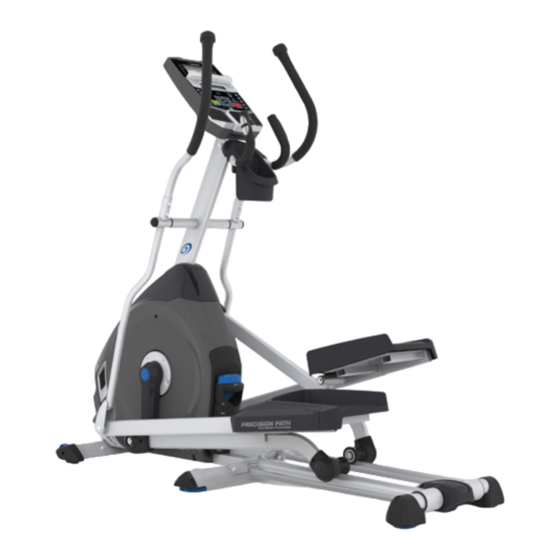
E614 (Model Year 2014) Elliptical
®
Fitness Machine Service Manual
1
Page Number
2
3
3
3
4
5
5
6
8
10
11
12
12
15
18
18
20
22
25
27
29
34
36
41
44
48
51
54
57
59
61
Service Manual
8008059.021516.B
Advertisement
Table of Contents

Related Manuals for Nautilus E614


Summary of Contents for Nautilus E614
-
Page 1: Table Of Contents
Nautilus, Inc., (800) NAUTILUS / (800) 628-8458, www.NautilusInc.com - Customer Service: North America (800) 605-3369, csnls@nautilus.com | outside U.S. technics@nautilus.com | © 2014 Nautilus, Inc. | ® indicates trademarks registered in the United States. These marks may be registered in other nations or otherwise protected by common law. -
Page 2: Important Safety Instructions
Nautilus, Inc., (800) NAUTILUS / (800) 628-8458, www.NautilusInc.com - Customer Service: North America (800) 605-3369, csnls@nautilus.com | outside U.S. technics@nautilus.com | © 2014 Nautilus, Inc. | ® indicates trademarks registered in the United States. These marks may be registered in other nations or otherwise protected by common law. -
Page 3: Safety Warning Labels And Serial Number
This product, its packaging, and components contain chemicals known to the State of California to cause cancer, birth defects, or reproductive harm. This Notice is provided in accordance with California’s Proposition 65. If you would like additional information, please refer to our website at www.nautilus.com/prop65. APPROVALS METRIC TOLERANCES. -
Page 4: Maintenance
Worn, damaged or loose components must be repaired or replaced immediately. Only manufacturer supplied components can be used to maintain and repair the equipment. If at any time the Warning labels become loose, unreadable or dislodged, contact Nautilus Customer Service for WA R N I N G replacement labels. -
Page 5: Moving The Machine
Moving the Machine The machine may be moved by one or more persons depending on their physical abilities and capacities. Make sure that you and others are all physically fit and able to move the machine safely. Use proper safety precautions and lifting techniques. Remove the power cord. -
Page 6: Troubleshooting
Troubleshooting Condition/Problem Things to Check Solution No display/partial display/ Check electrical (wall) Make sure unit is plugged into a functioning wall outlet. unit will not turn on outlet Check connection at front Connection should be secure and undamaged. Replace of unit adapter or connection at unit if either are damaged. - Page 7 Condition/Problem Things to Check Solution Check magnet position Magnet should be in place on pulley. (requires shroud removal) Check Speed Sensor Speed sensor should be aligned with magnet and connected to (requires shroud removal) data cable. Realign sensor if necessary. Replace if there is any damage to the sensor or the connecting wire.
-
Page 8: Console Service Mode
Console Service Mode – x614 / x616 series (MY14) Consoles The Console Setup Mode lets you input the date and time, set the units of measurement to either English or Metric, change the machine type, control the sound settings ( on/ off), or see maintenance statistics (Total Run Hours – for service technician use only). - Page 9 All LEDs Off 1 second Sequence Segments 1 at a time – on 1 second, off 1 second Press any key to exit test h. RUN LCD TEST – Drives 3x5 and 1x5 LCD displays with the following patterns: All segments on All segments off Set individual segments one at a time until all segments are illuminated.
-
Page 10: Maintenance Parts Exploded View
Maintenance Parts Exploded View Your machine may differ. Use only as a guide. Console Shroud, Right Handlebar Arm, Upper Left Heart Rate (HR) Cable Shroud Cap Transport Wheel Handlebar, Static Shroud, Upper Drive Belt Console Cable, Upper Shroud, Left Drive Pulley Arm Pivot Rod Console Cable, Lower Speed Sensor Magnet Console Mast... -
Page 11: Replacement Procedure Skill Level
REPLACEMENT PROCEDURE SKILL LEVEL Level I : Low - very little mechanical knowledge or exposure. Level II : Intermediate - some experience with mechanical procedures Level III : Advanced - knowledgeable about mechanical procedures WA R N I N G To reduce the risk of electrical shock or unsupervised usage of the equipment, always unplug the power D A N G E R cord from the wall outlet and wait 5 minutes before cleaning, maintaining or repairing this machine. -
Page 12: Adjust The Belt Tension
Nautilus, Inc., (800) NAUTILUS / (800) 628-8458, www.NautilusInc.com - Customer Service: North America (800) 605-3369, csnls@nautilus.com | outside U.S. technics@nautilus.com | © 2014 Nautilus, Inc. | ® indicates trademarks registered in the United States. These marks may be registered in other nations or otherwise protected by common law. - Page 13 NOTICE: It is necessary to remove the Shrouds for this procedure. Refer to the “Replace the Shrouds” procedure. To reduce the risk of electrical shock or unsupervised usage of the equipment, always unplug the power cord from the wall outlet and wait 5 minutes before cleaning, maintaining or repairing this machine.
- Page 14 To adjust the nuts (C) on the Tensioner Assembly (A), use a 10mm open end wrench to hold the bolt (B) steady and turn the nuts with a second 10mm open end wrench. When the tension is correct, tighten the nuts (C) against the Tensioner Bracket (D) to hold the bolt (B) and the Tensioner Assembly (A) in position.
-
Page 15: Set The Brake Tension
Nautilus, Inc., (800) NAUTILUS / (800) 628-8458, www.NautilusInc.com - Customer Service: North America (800) 605-3369, csnls@nautilus.com | outside U.S. technics@nautilus.com | © 2014 Nautilus, Inc. | ® indicates trademarks registered in the United States. These marks may be registered in other nations or otherwise protected by common law. - Page 16 NOTICE: It is necessary to remove the shrouds for this procedure. Refer to the “Replace the Shrouds” procedure. Note: Your machine may not match the image. For reference only. Disconnect and reconnect the AC Adapter from the wall outlet to turn the power off and on. Push QuickStart and verify that the console shows that the default resistance level is 4.
- Page 17 Note: If the cardboard is not 3mm (1/8”) thick, you can use the pages of a paperback book to measure the gap. Approximately 36 pages (sheets) = 3mm. Turn the power on again. Use the console to check the resistance adjustment. Machine is on.
-
Page 18: Part Replacement
Nautilus, Inc., (800) NAUTILUS / (800) 628-8458, www.NautilusInc.com - Customer Service: North America (800) 605-3369, csnls@nautilus.com | outside U.S. technics@nautilus.com | © 2014 Nautilus, Inc. | ® indicates trademarks registered in the United States. These marks may be registered in other nations or otherwise protected by common law. - Page 19 To reduce the risk of electrical shock or unsupervised usage of the equipment, always unplug the power cord from the wall outlet and the machine and wait 5 minutes before cleaning, maintaining or repairing the machine. Place the power cord in a secure location. Note: Your machine may not match the image.
- Page 20 Nautilus, Inc., (800) NAUTILUS / (800) 628-8458, www.NautilusInc.com - Customer Service: North America (800) 605-3369, csnls@nautilus.com | outside U.S. technics@nautilus.com | © 2014 Nautilus, Inc. | ® indicates trademarks registered in the United States. These marks may be registered in other nations or otherwise protected by common law.
- Page 21 To reduce the risk of electrical shock or unsupervised usage of the equipment, always unplug the power cord from the wall outlet and the machine and wait 5 minutes before cleaning, maintaining or repairing the machine. Place the power cord in a secure location. Note: Your machine may not match the image.
- Page 22 Nautilus, Inc., (800) NAUTILUS / (800) 628-8458, www.NautilusInc.com - Customer Service: North America (800) 605-3369, csnls@nautilus.com | outside U.S. technics@nautilus.com | © 2014 Nautilus, Inc. | ® indicates trademarks registered in the United States. These marks may be registered in other nations or otherwise protected by common law.
-
Page 23: Console
To reduce the risk of electrical shock or unsupervised usage of the equipment, always unplug the power cord from the wall outlet and the machine and wait 5 minutes before cleaning, maintaining or repairing the machine. Place the power cord in a secure location. Note: Your machine may not match the image. - Page 24 5. Using a small Flathead screwdriver, pry the Caps from the Lower Handlebar Arms. 13 mm 6. Using a 13 mm wrench, remove the hardware from the Lower Handlebar Arms and the Arm Pivot. Remove the Handlebar Arms and set them safely aside. 7.
- Page 25 Nautilus, Inc., (800) NAUTILUS / (800) 628-8458, www.NautilusInc.com - Customer Service: North America (800) 605-3369, csnls@nautilus.com | outside U.S. technics@nautilus.com | © 2014 Nautilus, Inc. | ® indicates trademarks registered in the United States. These marks may be registered in other nations or otherwise protected by common law.
- Page 26 To reduce the risk of electrical shock or unsupervised usage of the equipment, always unplug the power cord from the wall outlet and the machine and wait 5 minutes before cleaning, maintaining or repairing the machine. Place the power cord in a secure location. Note: Your machine may not match the image.
- Page 27 Nautilus, Inc., (800) NAUTILUS / (800) 628-8458, www.NautilusInc.com - Customer Service: North America (800) 605-3369, csnls@nautilus.com | outside U.S. technics@nautilus.com | © 2014 Nautilus, Inc. | ® indicates trademarks registered in the United States. These marks may be registered in other nations or otherwise protected by common law.
- Page 28 To reduce the risk of electrical shock or unsupervised usage of the equipment, always unplug the power cord from the wall outlet and the machine and wait 5 minutes before cleaning, maintaining or repairing the machine. Place the power cord in a secure location. Note: Your machine may not match the image.
- Page 29 Nautilus, Inc., (800) NAUTILUS / (800) 628-8458, www.NautilusInc.com - Customer Service: North America (800) 605-3369, csnls@nautilus.com | outside U.S. technics@nautilus.com | © 2014 Nautilus, Inc. | ® indicates trademarks registered in the United States. These marks may be registered in other nations or otherwise protected by common law.
- Page 30 To reduce the risk of electrical shock or unsupervised usage of the equipment, always unplug the power cord from the wall outlet and the machine and wait 5 minutes before cleaning, maintaining or repairing the machine. Place the power cord in a secure location. Note: Your machine may not match the image.
- Page 31 Using a 6mm hex key and a 13 mm wrench, remove the two indicated bolts from the Lower Handlebar Arms and Pedals. Set the hardware safely aside for reassembly. 13 mm Be aware that the Handlebar Arms will be loose and may pivot when the hardware is removed.
- Page 32 Using a 6mm hex key, remove the four bolts that attach the Lift Assembly to the Rail Assembly. Remove the Lift Assembly. If you are only replacing the Lift Assembly, go to Step 11. If you are replacing the Rail Assembly, continue to Step 7. Place a static object (like a book or box) under the back of the main frame but not under the Rail Assembly.
-
Page 33: Upper And Lower Handlebar Arms
11. Attach the new Lift Assembly using the Arm Pivot Rod. Note: Be sure Levelers are fully raised on Rail Assembly. NOTICE: With the Arm Pivot Rod under the plate junction, push the Lift Assembly toward the Frame Assembly and fully tighten hard- ware. -
Page 34: Transport Wheels, Front Endcaps And Footpads
Nautilus, Inc., (800) NAUTILUS / (800) 628-8458, www.NautilusInc.com - Customer Service: North America (800) 605-3369, csnls@nautilus.com | outside U.S. technics@nautilus.com | © 2014 Nautilus, Inc. | ® indicates trademarks registered in the United States. These marks may be registered in other nations or otherwise protected by common law. - Page 35 Note: Your machine may not match the image. For reference only. Place a static object (like a book or box) under the front stabilizer (C). The static object should not be compressible. Using a short #2 Phillips screwdriver, loosen and remove the screws (A1) from the Footpad (A), and set them safely aside.
- Page 36 Nautilus, Inc., (800) NAUTILUS / (800) 628-8458, www.NautilusInc.com - Customer Service: North America (800) 605-3369, csnls@nautilus.com | outside U.S. technics@nautilus.com | © 2014 Nautilus, Inc. | ® indicates trademarks registered in the United States. These marks may be registered in other nations or otherwise protected by common law.
- Page 37 To reduce the risk of electrical shock or unsupervised usage of the equipment, always unplug the power cord from the wall outlet and the machine and wait 5 minutes before cleaning, maintaining or repairing the machine. Place the power cord in a secure location. Note: Your machine may not match the image.
-
Page 38: Shrouds
Using a 6mm hex key, loosen and remove the indicated hardware from the Legs, and set it safely aside for reassembly. On each side of the machine, remove the Leg and Pedal together from the Rail Assembly and set them safely aside for reassembly. NOTICE: This step may require two people. - Page 39 Using a 14mm socket and ratchet, remove the Lock Nut from the Crank Arm with Plastics. Thread the Crank Puller into the Crank Arm with Plastics. When the Crank Puller is in the correct position, only 1-2 threads on the outer portion (CP2) of the Crank Puller should show. Note: Be sure the end of the Bolt (CP1) of the Crank Puller is flush with the Nut (CP2) as shown, before use.
- Page 40 12. Remove the Lift Cover Shroud (S) from the Lift Assembly. 13. Using a #2 Phillips screwdriver, remove the 3 screws that secure the Right Shroud. Remove the bottom screws first, and then the top screw. Slowly remove the Right Shroud. 14.
- Page 41 Nautilus, Inc., (800) NAUTILUS / (800) 628-8458, www.NautilusInc.com - Customer Service: North America (800) 605-3369, csnls@nautilus.com | outside U.S. technics@nautilus.com | © 2014 Nautilus, Inc. | ® indicates trademarks registered in the United States. These marks may be registered in other nations or otherwise protected by common law.
- Page 42 To reduce the risk of electrical shock or unsupervised usage of the equipment, always unplug the power cord from the wall outlet and the machine and wait 5 minutes before cleaning, maintaining or repairing the machine. Place the power cord in a secure location. Note: Your machine may not match the image.
- Page 43 Using a small flathead screwdriver, pry the Caps from 13 mm the Lower Handlebar Arms. Using a 13 mm wrench, remove the hardware from the Lower Handlebar Arms and the Arm Pivot Rod. Remove the hardware, Upper and Lower Handlebar Arms, and Arm Pivot Rod.
- Page 44 Nautilus, Inc., (800) NAUTILUS / (800) 628-8458, www.NautilusInc.com - Customer Service: North America (800) 605-3369, csnls@nautilus.com | outside U.S. technics@nautilus.com | © 2014 Nautilus, Inc. | ® indicates trademarks registered in the United States. These marks may be registered in other nations or otherwise protected by common law.
- Page 45 To reduce the risk of electrical shock or unsupervised usage of the equipment, always unplug the power cord from the wall outlet and the machine and wait 5 minutes before cleaning, maintaining or repairing the machine. Place the power cord in a secure location. Note: Your machine may not match the image.
- Page 46 Using a small flathead screwdriver, pry the Caps from 13 mm the Lower Handlebar Arms. Using a 13 mm wrench, remove the hardware from the Lower Handlebar Arms and the Arm Pivot Rod. Remove the hardware, Upper and Lower Handlebar Arms, and Arm Pivot Rod.
-
Page 47: Console Mast
Tie the length of string to the end (A) of the Data Cable at the base of the Mast. Hold the other end of the Data Cable (B) and carefully pull it out of the Mast so that the string extends through the length of the Mast. Untie the string from the old Data Cable and discard the old cable. - Page 48 Nautilus, Inc., (800) NAUTILUS / (800) 628-8458, www.NautilusInc.com - Customer Service: North America (800) 605-3369, csnls@nautilus.com | outside U.S. technics@nautilus.com | © 2014 Nautilus, Inc. | ® indicates trademarks registered in the United States. These marks may be registered in other nations or otherwise protected by common law.
-
Page 49: Brake Assembly
NOTICE: It is necessary to remove the Shrouds for this procedure. Refer to the “Replace the Shrouds” procedure. It may be necessary to adjust the brake tension at the end of this procedure. Refer to the “Set the Brake Tension” procedure. To reduce the risk of electrical shock or unsupervised usage of the equipment, always unplug the power cord from the wall outlet and the machine and wait 5 minutes before cleaning, maintaining or repairing the machine. - Page 50 Final Inspection Inspect your machine to ensure that all hardware is tight and components are properly assembled. Do not use until the machine has been fully assembled and inspected for correct performance in accordance with the Owner’s Manual. After replacing the Brake Assembly, the resistance levels of the machine may be different.
- Page 51 Nautilus, Inc., (800) NAUTILUS / (800) 628-8458, www.NautilusInc.com - Customer Service: North America (800) 605-3369, csnls@nautilus.com | outside U.S. technics@nautilus.com | © 2014 Nautilus, Inc. | ® indicates trademarks registered in the United States. These marks may be registered in other nations or otherwise protected by common law.
- Page 52 NOTICE: It is necessary to remove the Shrouds for this procedure. Refer to the “Replace the Shrouds” procedure. It may be necessary to adjust the brake tension at the end of this procedure. Refer to the “Set the Brake Tension” procedure. To reduce the risk of electrical shock or unsupervised usage of the equipment, always unplug the power cord from the wall outlet and the machine and wait 5 minutes before cleaning, maintaining or repairing the machine.
-
Page 53: Servo Motor
Use the pliers to unhook the Tension Spring (J) from the Main Frame. Pull back and release the Magnet Arm (K) enough to disengage it from the Motor Pulley Shaft (L). Loosen and remove the two socket head bolts (M) from the Servo Motor (A). - Page 54 Nautilus, Inc., (800) NAUTILUS / (800) 628-8458, www.NautilusInc.com - Customer Service: North America (800) 605-3369, csnls@nautilus.com | outside U.S. technics@nautilus.com | © 2014 Nautilus, Inc. | ® indicates trademarks registered in the United States. These marks may be registered in other nations or otherwise protected by common law.
- Page 55 NOTICE: It is necessary to remove the Shrouds for this procedure. Refer to the “Replace the Shrouds” procedure. It is necessary to adjust the Drive Belt tension at the end of this procedure. Refer to the “Belt Tension Adjustment” procedure To reduce the risk of electrical shock or unsupervised usage of the equipment, always unplug the power cord from the wall outlet and the machine and wait 5 minutes before cleaning, maintaining or repairing the machine.
-
Page 56: Tensioner Assembly (Idler Assembly)
Turn the Drive Pulley (Item G) clockwise while forcing the Drive Belt (H) to the outside. Belt will come off of the Drive Pulley. Keep fingers out of any pinch hazards when turning the Pulleys. To remove the hardware (I) from the Flywheel (A), use the 17 mm open end wrench to hold the nut on one side steady and remove the nut on the opposite side with the 17 mm socket and wrench. - Page 57 Nautilus, Inc., (800) NAUTILUS / (800) 628-8458, www.NautilusInc.com - Customer Service: North America (800) 605-3369, csnls@nautilus.com | outside U.S. technics@nautilus.com | © 2014 Nautilus, Inc. | ® indicates trademarks registered in the United States. These marks may be registered in other nations or otherwise protected by common law.
- Page 58 NOTICE: It is necessary to remove the Shrouds for this procedure. Refer to the “Replace the Shrouds” procedure. It is necessary to adjust the Drive Belt tension at the end of this procedure. Refer to the “Belt Tension Adjustment” procedure To reduce the risk of electrical shock or unsupervised usage of the equipment, always unplug the power cord from the wall outlet and the machine and wait 5 minutes before cleaning, maintaining or repairing the machine.
- Page 59 Nautilus, Inc., (800) NAUTILUS / (800) 628-8458, www.NautilusInc.com - Customer Service: North America (800) 605-3369, csnls@nautilus.com | outside U.S. technics@nautilus.com | © 2014 Nautilus, Inc. | ® indicates trademarks registered in the United States. These marks may be registered in other nations or otherwise protected by common law.
-
Page 60: Rpm Sensor (Speed Sensor)
NOTICE: It is necessary to remove the Shrouds for this procedure. Refer to the “Replace the Shrouds” procedure. To reduce the risk of electrical shock or unsupervised usage of the equipment, always unplug the power cord from the wall outlet and the machine and wait 5 minutes before cleaning, maintaining or repairing the machine. Place the power cord in a secure location. - Page 61 Nautilus, Inc., (800) NAUTILUS / (800) 628-8458, www.NautilusInc.com - Customer Service: North America (800) 605-3369, csnls@nautilus.com | outside U.S. technics@nautilus.com | © 2014 Nautilus, Inc. | ® indicates trademarks registered in the United States. These marks may be registered in other nations or otherwise protected by common law.
-
Page 62: Power Inlet
NOTICE: It is necessary to remove the Shrouds for this procedure. Refer to the “Replace the Shrouds” procedure. To reduce the risk of electrical shock or unsupervised usage of the equipment, always unplug the power cord from the wall outlet and the machine and wait 5 minutes before cleaning, maintaining or repairing the machine.