National Instruments VXI-MXI-Express Series User Manual
Hide thumbs
Also See for VXI-MXI-Express Series:
- Installation manual (8 pages) ,
- User manual (72 pages)
Table of Contents

Related Manuals for National Instruments VXI-MXI-Express Series


Summary of Contents for National Instruments VXI-MXI-Express Series
- Page 1 National Instruments VXI-8360T Manual Get Pricing & Availability at ApexWaves.com Call Today: 1-800-915-6216 Email: sales@apexwaves.com https://www.apexwaves.com/vxi/national-instruments/vxi-and-vme-remote-controllers/VXI-8360T...
- Page 2 VXI-MXI -Express VXI-MXI-Express Series User Manual NI VXI-8360T NI VXI-8360LT VXI-MXI-Express Series User Manual April 2012 373683A-01...
- Page 3 11500 North Mopac Expressway Austin, Texas 78759-3504 USA Tel: 512 683 0100 For further support information, refer to the Technical Support and Professional Services appendix. To comment on National Instruments documentation, refer to the National Instruments Web site at and enter ni.com/info the Info Code feedback ©...
- Page 4 Instruments Corporation. National Instruments respects the intellectual property of others, and we ask our users to do the same. NI software is protected by copyright and other intellectual property laws. Where NI software may be used to reproduce software or other materials belonging to others, you may use NI software only to reproduce materials that you may reproduce in accordance with the terms of any applicable license or other legal restriction.
- Page 5 CUSTOMIZED AND DIFFERS FROM NATIONAL INSTRUMENTS' TESTING PLATFORMS AND BECAUSE A USER OR APPLICATION DESIGNER MAY USE NATIONAL INSTRUMENTS PRODUCTS IN COMBINATION WITH OTHER PRODUCTS IN A MANNER NOT EVALUATED OR CONTEMPLATED BY NATIONAL INSTRUMENTS, THE USER OR APPLICATION DESIGNER IS ULTIMATELY...
- Page 6 Furthermore, any changes or modifications to the product not expressly approved by National Instruments could void your authority to operate it under your local regulatory rules.
-
Page 7: Table Of Contents
Connecting Cables...................2-4 Powering On/Off the MXI-Express System............2-4 Software Configuration....................2-5 Default Software Settings................2-7 Chapter 3 Developing Your Application National Instruments Application Software ..............3-1 NI-VXI, NI-VISA, and Related Terms................3-2 Programming for VXI....................3-3 Optimizing Large VXIbus Transfers...............3-4 NI-VXI API Notes...................3-5 Compiler Symbols................3-5 Compatibility Layer Options ............3-5 ©... - Page 8 Using the Trigger Ports on the NI VXI-8360LT Appendix E How to Fix an Invalid EEPROM Configuration Appendix F VMEbus Capability Codes Appendix G Common Questions Appendix H Technical Support and Professional Services Glossary Index VXI-MXI-Express Series User Manual viii ni.com...
-
Page 9: About This Manual
Italic text denotes variables, emphasis, a cross-reference, or an introduction to a key concept. Italic text also denotes text that is a placeholder for a word or value that you must supply. © National Instruments VXI-MXI-Express Series User Manual... -
Page 10: Related Documentation
PCI-PCI Bridge Architecture Specification, Revision 1.2 • PCI Express Specification, Revision 1.0a • PICMG CompactPCI 2.0 R3.0 specification • PICMG EXP.0 CompactPCI Express Specification R1.0 • PCMCIA ExpressCard Standard, Revision 1.0 • PCI Express Base Specification, Revision 1.1 VXI-MXI-Express Series User Manual ni.com... -
Page 11: Introduction
VXI devices that need P3 support. The NI VXI-8360T/LT controller links a PCI Express-based host computer to the VXIbus using the National Instruments MXI-Express x1 interface. The MXI-Express x1 link enables your computer to perform as though it were plugged directly into the VXI backplane, giving it the capabilities of an embedded computer. - Page 12 VXI device drivers, NI-VISA, MAX, Resman, and other useful utilities. This software also enables additional features of the NI VXI-8360T/LT, such as Variable Power On (VPO) support, that are not covered in this manual. Refer to the respective software release notes for more information. VXI-MXI-Express Series User Manual ni.com...
-
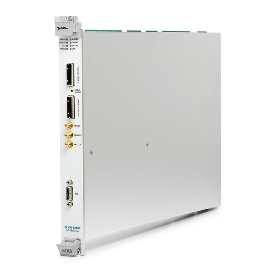
Page 13: Ni Vxi-8360T Front Panel Features
Blinking Red—Indicates incorrect trigger cable connection. – Solid Green—Indicates correct trigger cable connection. • Three front panel SMB connectors for: – Trigger input – Trigger output – CLK10 I/O • One MXI-Express x1 connector © National Instruments VXI-MXI-Express Series User Manual... -
Page 14: Ni Vxi-8360Lt Front Panel Features
Two Trigger Bus Ports—These ports allow the user to daisy chain the 8 M-LVDS backplane triggers and/or CLK10 between multiple chassis. • Three front panel SMB connectors for: – Trigger input – Trigger output – CLK10 I/O • One MXI-Express x1 connector VXI-MXI-Express Series User Manual ni.com... -
Page 15: Functional Block Diagrams
MITE ASIC PXI/PCI PCIe-to PCI Bridge MXI-Express x1 MANTIS PCIe Gen 1 x1 Copper ASIC 1 Status LEDs 2 Trigger Bus Ports 3 SMB I/O Figure 1-2. NI VXI-8360LT (152725x-01) Functional Block Diagram © National Instruments VXI-MXI-Express Series User Manual... -
Page 16: Mxi-Express X1 Functional Overview
Compatibility Software to handle the enumeration process of these resources. In the cases where this software is required, there may be a dip switch on the MXI-Express x1 host adapter that needs to be toggled as instructed by the documentation for the software. VXI-MXI-Express Series User Manual ni.com... -
Page 17: Basic Mxi-Express X1 Systems
Refer to the MXI-Express x1 Series User Manual or the Set Up Your MXI-Express x1 System guide included in your kit for more information about MXI-Express x1 connectivity support for the NI VXI-8360T/LT controller. © National Instruments VXI-MXI-Express Series User Manual... -
Page 18: Larger Mxi-Express X1 Systems
MXI-Express x1 products. Star Topology Daisy-Chain Topology Figure 1-4. Example MXI-Express x1 System Expansion Topologies The NI VXI-8360T/LT controller cannot be used to daisy-chain the MXI-Express Note x1 link from one VXI mainframe to another VXI mainframe. VXI-MXI-Express Series User Manual ni.com... -
Page 19: Installation And Configuration
NI VXI-8360T and NI VXI-8360LT. ❑ A VXIbus mainframe ❑ A NI VXI-8360T/LT controller ❑ MXI-Express x1 copper cable ❑ National Instruments NI-VXI driver software CD Some x16 slots may not work correctly with MXI-Express adapters. © National Instruments VXI-MXI-Express Series User Manual... -
Page 20: Unpacking
Setup. They are in the subdirectory of your NI-VXI directory, usually Program Files\National Instruments\VXI When the installation process completes, reboot the system for the changes to take effect. If you backed up the manufacturer and model name files, VXI-MXI-Express Series User Manual ni.com... -
Page 21: Hardware Installation And Configuration
If you save and restore the TBL files from an older version of NI-VXI, the software will use TBL files that do not have the latest updates from National Instruments and may not include recent hardware releases. If you added additional manufacturer or model names to your TBL files, we recommend merging those changes with the latest updates included with this version of NI-VXI, so that all your devices are properly identified. -
Page 22: Installing Your Mxi-Express X1 Host Adapter Or Peripheral
Help»Help Topics menu. Powering On/Off the MXI-Express System For instructions, refer to the Powering On the MXI-Express x1 System section and Powering Off the MXI-Express x1 System section of the Setup Your MXI-Express x1 System guide. VXI-MXI-Express Series User Manual ni.com... -
Page 23: Software Configuration
NI VXI-8360T/LT controller. Complete the following steps to configure the VXI System. Open MAX. Select the VXI system that is controlled by the NI VXI-8360T/LT controller listed under Devices and Interfaces. © National Instruments VXI-MXI-Express Series User Manual... - Page 24 If you are using extenders such as MXI-2 to create a multichassis system, you may Note need to run Resman before configuring some of your devices. Verify the configuration, as needed, through the interactive control utility, VISAIC (Start»Programs» National Instruments»VISA» VISA Interactive Control), as described in Chapter 3, Developing Your Application.
-
Page 25: Default Software Settings
VXI retry generation Enabled Automatic retries Enabled VXI transfer limit A24/A32 write posting Enabled Requester mode Release on Request Request level Operate as fair requester Enabled Bus arbitration mode Prioritized Arbiter timeout Disabled © National Instruments VXI-MXI-Express Series User Manual... - Page 26 512 KB DMA setting Enable DMA on this controller Table 2-5. MAX SMB Tab Default Settings Editor Field Default Setting CLK10 50 Ω termination Disabled Invert CLK10 polarity Enabled TRIG IN 50 Ω termination Disabled VXI-MXI-Express Series User Manual ni.com...
-
Page 27: Developing Your Application
Each component assists you with one of four development steps: configuration, device interaction, programming, and debugging. You can access the utilities, help files, and release notes through the Windows Start menu by opening the National Instruments»VXI or National Instruments»VISA program groups. National Instruments Application Software In addition to the NI-VISA/NI-VXI software, you can use the National ™... -
Page 28: Ni-Vxi, Ni-Visa, And Related Terms
• NI-VISA is the native API for communicating with VXI/VME devices. NI-VISA is the National Instruments implementation of the VISA I/O standard, which is a common interface to many types of instruments (such as VXI, GPIB, PXI, Serial, TCP/IP, and so on). NI-VXI is optimized for use through NI-VISA, and NI recommends using NI-VISA to develop all new VXI/VME applications. -
Page 29: Programming For Vxi
Programming for VXI NI-VISA and the NI-VXI API are the two National Instruments programming interfaces for accessing your VXI/VME instruments. With NI-VXI 3.0 or later, NI-VISA is the native API for communicating with a VXI or VME system, and NI recommends using it for all new applications. -
Page 30: Optimizing Large Vxibus Transfers
Windows operating system, use a contiguous buffer so the move operation does not need to build a scatter-gather list for the user buffer. Note viMemAlloc() returns 32-bit aligned, page-locked, VXImemAlloc() continuous buffers that work efficiently with the move operations. VXI-MXI-Express Series User Manual ni.com... -
Page 31: Ni-Vxi Api Notes
NI-VXI API Notes The following notes apply only if you are using the NI-VXI API. National Instruments recommends that all new VXI/VME applications use the NI-VISA API, but you can still develop with the older NI-VXI API for compatibility with legacy code. -
Page 32: Device Interaction And Debugging Tools
NI-VXI installation. NI I/O Trace NI I/O Trace tracks the calls your application makes to National Instruments drivers, including NI-VISA, NI-VXI, and NI-488. NI I/O Trace highlights functions that return errors, so during development you can quickly spot which functions failed during a program’s execution. -
Page 33: Visa Interactive Control (Visaic)
Try the following in VISAIC: In the tree view, navigate using your mouse to the VISA resource for your controller—probably VXI0::0::INSTR, representing the VXI system 0, logical address 0 instrument resource, as shown in Figure 3-2. © National Instruments VXI-MXI-Express Series User Manual... - Page 34 16-bits and other parameters set to default values. The In Value field shows the I/O operation result, such as . The Return Data field shows the 0x8ff6 function status, such as , as shown in No Error VI_SUCCESS Figure 3-3. VXI-MXI-Express Series User Manual ni.com...
-
Page 35: Vxi Interactive Control (Vic)
You can also use VXI Interactive Control Program (VIC) to control your VXI/VME devices and develop and debug VXI application programs. You can launch VISAIC (or VIC) from the Tools menu in MAX or from the VISA or VXI subgroups in Start»Programs»National Instruments. © National Instruments VXI-MXI-Express Series User Manual... -
Page 36: Appendix A Specifications
NI assembly number that is printed on either the front or back side of the board. For specifications on other MXI-Express x1 products that can connect to the NI VXI-8360T and NI VXI-8360LT, refer to the MXI-Express x1 Series User Manual. © National Instruments VXI-MXI-Express Series User Manual... - Page 37 Dimensions ..........23.3 × 34.0 cm (9.2 × 13.4 in.) Weight ............1.3 kg (46.8 oz) Slot requirements ........Single VXI C-size slot Compatibility ..........Fully compatible with VXI specification VXI keying class ........Class 1 TTL MTBF .............Contact factory VXI-MXI-Express Series User Manual ni.com...
- Page 38 TRIG OUT SMB Connector Output drive ........... 50 Ω line driver Voltage level..........2.0 V minimum into 50 Ω (typical) Output coupling........DC TRIG IN TRIG OUT EXT CLK (CLK10) Figure A-1. Front Panel SMB Connectors © National Instruments VXI-MXI-Express Series User Manual...
- Page 39 Table A-1. SMB Connector Pinout Signal Name Signal Description SIGNALCONDUCTOR Trigger/CLK 2 (Shield) Ground MXI-Express x1 Connector MXI-Express x1 Connector Pin Number Signal Description PERn0 PERp0 RSVD SB_RTN CREFCLK– CREFCLK+ PWR_RTN CPERST# RSVD CWAKE# CPRSNT# CPWRON PETn0 PETp0 VXI-MXI-Express Series User Manual ni.com...
- Page 40 (Tested in accordance with IEC-60068-2-56.) EMI ............FCC Class A verified, EC verified Not to be used for MXI-Express communication. Additional devices sharing the bus may function, but is not supported by National Instruments. © National Instruments VXI-MXI-Express Series User Manual...
- Page 41 In the United States (per FCC 47 CFR), Class A equipment is intended for use in Note commercial, light-industrial, and heavy-industrial locations. In Europe, Canada, Australia and New Zealand (per CISPR 11) Class A equipment is intended for use only in heavy-industrial locations. VXI-MXI-Express Series User Manual ni.com...
- Page 42 For additional environmental information, refer to the NI and the Environment Web page at . This page contains the ni.com/environment environmental regulations and directives with which NI complies, as well as other environmental information not included in this document. © National Instruments VXI-MXI-Express Series User Manual...
- Page 43 (For information about China RoHS compliance, go to ni.com/environment/rohs_china Cleaning If you need to clean the module, use a soft, nonmetallic brush. Make sure that the module is completely dry and free from contaminants before returning it to service. VXI-MXI-Express Series User Manual ni.com...
- Page 44 Dimensions..........23.3 × 34.0 cm (9.2 × 13.4 in.) Weight............ 1.3 kg (47.2 oz) Slot requirements ........Single VXI C-size slot Compatibility ......... Fully compatible with VXI specification VXI keying class........Class 1 TTL MTBF............. 322,638 hours © National Instruments VXI-MXI-Express Series User Manual...
- Page 45 TRIG OUT SMB Connector Output drive ..........50 Ω line driver Voltage level..........2.0 V minimum into 50 Ω (typical) Output coupling ........DC TRIG IN TRIG OUT EXT CLK (CLK10) Figure A-2. Front Panel SMB Connectors VXI-MXI-Express Series User Manual A-10 ni.com...
- Page 46 Signal Name Signal Description SIGNALCONDUCTOR Trigger/CLK 2 (Shield) Ground MXI-Express x1 Connector MXI-Express x1 Connector Pin Number Signal Description PERn0 PERp0 RSVD SB_RTN CREFCLK– CREFCLK+ PWR_RTN CPERST# RSVD CWAKE# CPRSNT# CPWRON PETn0 PETp0 © National Instruments A-11 VXI-MXI-Express Series User Manual...
- Page 47 Physical interface........TIA/EIA899 M-LVDS compatible Bus transceiver..........Texas Instruments SN65MLVD080 Maximum trigger bus length ....20 m of cables Maximum number of devices on bus ..6 Additional devices sharing the bus may function, but is not supported by National Instruments. VXI-MXI-Express Series User Manual A-12 ni.com...
- Page 48 LXI1p LXI1n LXI3p LXI3n LXI5p LXI5n RSVD LXI7p LXI7n LXI0p LXI0n RSVD LXI2p LXI2n LXI4p LXI4n LXI6p LXI6n RSVD Environmental Maximum altitude ........2,000 m Pollution Degree ........2 Indoor use only. © National Instruments A-13 VXI-MXI-Express Series User Manual...
- Page 49 MIL-PRF-28800F Class 2 limits.) Random vibration Operating .........5 to 500 Hz, 0.3 g Nonoperating ........5 to 500 Hz, 2.4 g (Tested in accordance with IEC-60068-2-64. Nonoperating test profile exceeds the requirements of MIL-PRF-28800F, Class 3.) VXI-MXI-Express Series User Manual A-14 ni.com...
- Page 50 Note For EMC declarations and certifications, and additional information, refer to the Online Product Certification section. © National Instruments A-15 VXI-MXI-Express Series User Manual...
- Page 51 (For information about China RoHS compliance, go to ni.com/environment/rohs_china Cleaning If you need to clean the module, use a soft, nonmetallic brush. Make sure that the module is completely dry and free from contaminants before returning it to service. VXI-MXI-Express Series User Manual A-16 ni.com...
- Page 52 Backplane trigger I/O For the jumper locations and default settings, see Figure B-1, Default Jumper Settings. Note To gain access to the jumpers, remove the side panel cover that is fastened with screws. © National Instruments VXI-MXI-Express Series User Manual...
- Page 53 W5—MITE CONFIGURATION W7—TRIG CARD CLK10 DIR 1-2—FACTORY 1-2—OUT 2-3—USER (DEFAULT) 2-3—IN (DEFAULT) J2—SLOT 0 DETECT 1-2—NON-SLOT 0 3-4—AUTO DETECT (DEFAULT) 5-6—SLOT 0 W8—MITE SELF CONFIG 1-2—DISABLE 2-3—ENABLE (DEFAULT) Figure B-1. VXI-MXI-Express Factory Default Jumper Settings VXI-MXI-Express Series User Manual ni.com...
- Page 54 As required by the specification, when installed in Slot 0, the NI VXI-8360T/LT controller drives CLK10, a differential ECL output, to the VXIbus backplane. When the system is not installed in Slot 0 it will only receive the CLK10 signal. © National Instruments VXI-MXI-Express Series User Manual...
- Page 55 The front panel TRIG/CLK PORT A(B). CLK10 (NI VXI-8360T Only) can be routed into the NI VXI-8360T from another NI VXI-8360T through the TRIG/CLK PORT A(B) on the front panel. Onboard jumpers are used to set this configuration. VXI-MXI-Express Series User Manual ni.com...
- Page 56 CLK10 Routing Options NI VXI-8360T Only External CLK 10 Source Select To/From TRG/CLK PORT CLK 10 Source Select Trig Card CLK 10 Dir External To/From Backplane To/From SMB SMB CLK Dir Internal 10 MHz Oscillator ±100 ppm Figure B-3. CLK10 Routing Options...
- Page 57 Table B-1. NI VXI-8360T/LT Slot O CLK10 Routing Options and Jumper Configurations EXT CLK TRG/CLK Product CLK10 Source Front Panel SMB Ports NI VXI-8360T CLK10 Out Internal NI VXI-8360T/LT Internal Internal Oscillator NI VXI-8360T CLK10 Out Internal CLK10 Out NI VXI-8360T/LT Internal NI VXI-8360T CLK10 Out...
- Page 58 This setting can be found in the hardware configuration panels in MAX, as shown in Figure B-4. Parallel termination is not necessary when the signal is driven by a 50 Ω source, Note such as a NI VXI-8360T/LT controller. © National Instruments VXI-MXI-Express Series User Manual...
- Page 59 In general, however, you should leave W8 in its factory-default setting. Figure B-5 shows the possible configurations for W8. a. Enable (default) b. Disable Figure B-5. Power-on Self Configuration Status VXI-MXI-Express Series User Manual ni.com...
- Page 60 MXI-Express x4 or PCI Express x4 device. The trigger bus may be able to support more devices and/or greater cable lengths, but these configurations have not been validated by National Instruments and are not currently supported. Connecting the Trigger Port Cables...
- Page 61 Do not map the same trigger out of the frame on more than one device on the trigger Note bus. This will cause the bus to be driven by more than one device. Protection circuitry prevents this from causing physical damage, however your setup will not function properly. VXI-MXI-Express Series User Manual ni.com...
- Page 62 To map CLK10 Out of the Frame set jumper W7 to connect pins 1-2. To map CLK10 In to the Frame set jumper W7 to connect pins 2-3. Refer to Appendix B, Advanced Hardware Configuration Settings, for more information about setting the hardware jumper. © National Instruments VXI-MXI-Express Series User Manual...
- Page 63 The wired VXI backplane trigger bus may be capable of supporting more devices over greater cable lengths but, these configurations have not been validated by National Instruments. The 8 triggers on the wired VXI backplane trigger bus correspond to the 8 TTL triggers on the VXI backplane (e.g., TTLTRG0* on the VXI...
- Page 64 Hardware switches located on the top edge of the NI VXI-8360LT control the operating mode of the trigger. The factory default switch settings for all 8 triggers are displayed in Figure D-1, Trigger Configuration Sticker (Located on the Side of the NI VXI-8360LT). VXI-MXI-Express Series User Manual ni.com...
- Page 65 Right click on your device and select Properties. Click on the Signal Mappings Tab. For each TTL Trigger select Into the Frame, Out of the Frame, or None. Click OK and re-run the Resman for the changes to take effect. © National Instruments VXI-MXI-Express Series User Manual...
- Page 66 If the device is going to be a receiver, set the trigger hardware switch to Receiver. Note Ensure only one receiving device is configured as the Receiver w/BIAS Device. Having more than one bias device on a trigger channel will produce undefined results. VXI-MXI-Express Series User Manual ni.com...
- Page 67 Settings, for jumper locations. Figure E-1 shows the configuration settings for EEPROM operation. Use jumper W5 to control whether the NI VXI-8360T/LT controller boots off the factory-configured EEPROM settings or the user-modified settings. © National Instruments VXI-MXI-Express Series User Manual...
- Page 68 10. Change jumper W5 back to the default position, as shown in Figure E-1. 11. Power on the computer. If the computer does not boot with this configuration, you will need to repeat these steps, modifying your configuration until a final configuration is reached. VXI-MXI-Express Series User Manual ni.com...
- Page 69 D32, D16, D08(O) (Interrupt Handler) VMEbus D32, D16, D08(O) interrupt handler D32, D16, D08(O) (Interrupter) VMEbus D32, D16, D08(O) interrupter ROAK, RORA Release on Acknowledge or Register Access interrupter BTO(x) VMEbus bus timer (programmable limit) © National Instruments VXI-MXI-Express Series User Manual...
- Page 70 MXI-Express x1 copper cable? The maximum length for the NI VXI-8360T/LT controller MXI-Express x1 copper cable is 7 m. National Instruments offers 1 m, 3 m, and 7 m copper cables. I need more devices than can fit in one chassis. How can I expand my...
- Page 71 Run Resman whenever you need to configure your VXI instruments (for example, when you power cycle either the host computer or the chassis). When you set a National Instruments controller to Logical Address 0, you will at some point need to run Resman to configure your VXI instruments.
- Page 72 The CLK10 generated by the NI VXI-8360T/LT controller is ±100 ppm per the VXI specification. To use a more accurate reference for CLK10, connect the signal to the controller through the EXT CLK SMB input on the front panel. © National Instruments VXI-MXI-Express Series User Manual...
- Page 73 You can also register for instructor-led, hands-on courses at locations around the world. • System Integration—If you have time constraints, limited in-house technical resources, or other project challenges, National Instruments © National Instruments VXI-MXI-Express Series User Manual...
- Page 74 You also can visit the Worldwide Offices section of ni.com/niglobal to access the branch office Web sites, which provide up-to-date contact information, support phone numbers, email addresses, and current events. VXI-MXI-Express Series User Manual ni.com...
- Page 75 Valid numbers for n are 16, 24, 32, and 64. In VME/VXI, because there are six address modifiers, there are 64 possible address spaces. ANSI American National Standards Institute © National Instruments Glossary-1 VXI-MXI-Express Series User Manual...
- Page 76 An error that signals failed access to an address. Bus errors occur with low-level accesses to memory and usually involve hardware with bus mapping capabilities. For example, nonexistent memory, a nonexistent register, or an incorrect device access can cause a bus error. VXI-MXI-Express Series User Manual Glossary-2 ni.com...
- Page 77 DMA is the fastest method of transferring data to/from computer memory. DRAM Dynamic RAM (Random Access Memory)—storage that the computer must refresh at frequent intervals. © National Instruments Glossary-3 VXI-MXI-Express Series User Manual...
- Page 78 EEPROM and flash memory that can be updated with a special utility (part of MAX). In combination with the hardware, the firmware enables the NI VXI-8360T/LT controller to act as a translator between USB and VXI protocols. VXI-MXI-Express Series User Manual Glossary-4 ni.com...
- Page 79 CPU should suspend its current task to service a designated activity. interrupt handler A VMEbus functional module that detects interrupt requests generated by interrupters and responds to those requests by requesting status and identify information. © National Instruments Glossary-5 VXI-MXI-Express Series User Manual...
- Page 80 These devices are able to use Word Serial Protocol to communicate with one another through communication registers. MODID Module ID lines—used in VXI to geographically locate boards and to dynamically configure boards. MTBF Mean Time Between Failure VXI-MXI-Express Series User Manual Glossary-6 ni.com...
- Page 81 NI-DAQ The National Instruments industry-standard software for data acquisition instruments. NI-VISA The National Instruments implementation of the VISA standard; an interface-independent software that provides a unified programming interface for VXI, GPIB, and serial instruments. NI-VXI The National Instruments bus interface software for VME/VXIbus systems.
- Page 82 Register-based devices are typically controlled by message-based devices via device-dependent register reads and writes. Resman The name of the National Instruments Resource Manager in NI-VXI bus interface software. See also Resource Manager. Resource Manager A message-based Commander located at Logical Address 0, which...
- Page 83 Installing such a device into any other slot can damage the device, the VMEbus/VXIbus backplane, or both. VXIbus VMEbus Extensions for Instrumentation © National Instruments Glossary-9 VXI-MXI-Express Series User Manual...
- Page 84 A mechanism that signifies that a device will immediately give a successful acknowledge to a write transfer and place the transfer in a local buffer. The device can then independently complete the write cycle to the destination. VXI-MXI-Express Series User Manual Glossary-10 ni.com...
- Page 85 (NI resources), H-1 compiler symbols, 3-5 EXT CLK specifications, A-3, A-10 configuration, 2-1 additional, star (figure), 1-8 advanced hardware settings, B-1 advanced options, B-1 front panel features, 1-3, 1-4 NI VXI-8360T trigger ports, C-1, D-1 © National Instruments VXI-MXI-Express Series User Manual...
- Page 86 NI VXI-8360T/LT controller, G-2 LabVIEW, 3-1 using to perform startup Resource LabWindows/CVI, 3-2 Manager operations, G-2 larger MXI-Express x1 systems, 1-8 NI-VXI API, 3-2 compatibility layer options, 3-5 compiler symbols, 3-5 notes, 3-5 VXI-MXI-Express Series User Manual ni.com...
- Page 87 A-6, A-14 cabling (figure), C-2 slot 0 detection connector configuration, B-5 signals (table), A-4, A-11 J2 jumper (figure), B-5 software configuration, C-2 SMB tab default settings (table), 2-8 troubleshooting (NI resources), H-1 © National Instruments VXI-MXI-Express Series User Manual...
- Page 88 VXIbus, CLK10 routing, B-6 optional settings inverting CLK10, B-9 Web resources, H-1 figure, B-9 WEEE information, A-8, A-16 termination, B-9 VXI-MXI-Express series controller application development, 3-1 common questions, G-1 configuration, 2-1 copper cable lengths, G-1 VXI-MXI-Express Series User Manual ni.com...