Table of Contents
Advertisement
Quick Links
W
ORK
H
ORIZONTAL
O
PERATION
Information included herein is controlled by the Export Administration Regulations (EAR) and may
require an export license, license exception or other approval from the appropriate U.S.
Government agency before being exported from the United States or provided to any foreign
person. Diversion contrary to U.S. law is prohibited.
H
ORSE
H-ADCP
M
ANUAL
P/N 957-6212-00 (May 2015)
© 2015 Teledyne RD Instruments, Inc. All rights reserved.
Advertisement
Table of Contents
Troubleshooting

Related Manuals for Teledyne WORKHORSE


Summary of Contents for Teledyne WORKHORSE
- Page 1 ANUAL P/N 957-6212-00 (May 2015) © 2015 Teledyne RD Instruments, Inc. All rights reserved. Information included herein is controlled by the Export Administration Regulations (EAR) and may require an export license, license exception or other approval from the appropriate U.S.
- Page 2 Page ii EAR-Controlled Technology Subject to Restrictions Contained on the Cover Page.
-
Page 3: Table Of Contents
ABLE OF ONTENTS 1 - A ...........................1 HAPTER LANCE How to Contact Teledyne RD Instruments ....................2 Conventions Used in this Manual......................... 2 System Overview ............................3 Inventory List ............................... 5 Computer Considerations ..........................6 Power Overview ............................7 Setting up the H-ADCP System ........................8 Connecting to the H-ADCP ........................ - Page 4 Applying Antifouling Paints ......................56 Removing Biofouling ........................58 Zinc Anode Inspection and Replacement ..................... 58 Zinc Anode Inspection ........................58 Zinc Anode Electrical Continuity Check ..................59 Zinc Anode Replacement ....................... 59 Calibrating the Compass........................60 Compass Background ........................60 Preparing for Calibration........................
- Page 5 Sensors ............................94 6 - R TRDI ....................99 HAPTER ETURNING YSTEMS TO ERVICE Shipping the H-ADCP ............................ 100 Returning Systems to the TRDI Factory ......................101 Returning Systems to TRDI Europe Factory ....................102 7 - S ..........................105 HAPTER PECIFICATIONS Outline Installation Drawings ........................
- Page 6 CR – Retrieve Parameters ......................144 CS – Start Pinging (Go) ........................144 CY - Clear Error Status Word ......................145 CZ – Power Down H-ADCP ......................146 Environmental Commands ........................... 147 Available Environmental Commands ....................147 Environmental Command Descriptions ....................147 EA - Heading Alignment .........................
- Page 7 TG – Time of First Ping (Y2k Compliant) ..................170 TP – Time Between Pings ....................... 171 TS – Set Real-Time Clock ........................ 171 TT – Set Real-Time Clock (Y2k Compliant)..................172 Water Profiling Commands .......................... 173 Standard Water Profiling Commands ....................173 WA - False Target Threshold Maximum ..................
- Page 8 Example Wakeup Banners ......................194 9 – O ........................195 HAPTER UTPUT ORMAT Choosing a Data Format ..........................196 PD0 Output Data Format ..........................198 Header Data Format ..........................199 Fixed Leader Data Format ........................201 Variable Leader Data Format ....................... 206 Converting ADC Channels ......................
- Page 9 Figure 12. Optional Mounting Kit (P/N 757K6085-00) ................23 Figure 13. 300 kHz NB H-ADCP Mounting Holes ..................24 SurfaceView Deployment Screen ..................... 28 Figure 14. SurfaceView Intensity Profile ....................28 Figure 15. Figure 16. Barnacle Damage to a Urethane Face ..................29 Figure 17.
- Page 10 Table 7: Pre-deployment Test (PA) Possible Cause of Failures .............. 88 Table 8: Water Profiling Specifications ....................107 Table 9: Specifications ......................... 107 Table 10: Outline Installation Drawings ....................108 Table 11: ADCP Minimum Required Commands for Deployments ............118 Table 12: H-ADCP Input Command Summary ..................
- Page 11 EVISION ISTORY May 2015 • Combined Quick Start Guide into the Operation Manual. • Created new H-ADCP setup card. • Added corrections for ICN 126 antifouling paint. • Added corrections for ICN 127 Force Cold Start. • Added corrections for ICN 130 End Cap Removal. •...
- Page 12 XCLUSIONS AND MISSIONS 1: None Page xii EAR-Controlled Technology Subject to Restrictions Contained on the Cover Page.
-
Page 13: Chapter 1 - A T A Glance
WorkHorse H-ADCP Operation Manual May 2015 Chapter LANCE In this chapter, you will learn: • H-ADCP Models and Options • System Overview • Computer Considerations • Power Overview • Setting up the H-ADCP • Caring for your H-ADCP System Page 1... -
Page 14: How To Contact Teledyne Rd Instruments
For all your customer service needs including our emergency 24/7 technical support, call +1 (858) 842-2700 Conventions Used in this Manual Conventions used in the WorkHorse Horizontal Acoustic Doppler Current Profiler (H-ADCP) Operation Manual have been established to help learn how to use the system quickly and easily. -
Page 15: System Overview
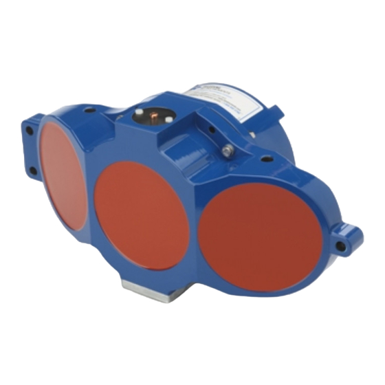
WorkHorse H-ADCP Operation Manual May 2015 System Overview The H-ADCP transducer assembly contains the end-cap, housing, transducer ceramics, and electronics. The standard acoustic frequencies are 600 and 300 kHz. See the Outline Installation Drawings for dimen- sions and weights. Picture... -
Page 16: Figure 1. 300/600 Khz H-Adcp Overview
May 2015 WorkHorse H-ADCP Operation Manual Figure 1. 300/600 kHz H-ADCP Overview Figure 2. 300 kHz NB H-ADCP Overview Page 4 EAR-Controlled Technology Subject to Restrictions Contained on the Cover Page. -
Page 17: Inventory List
WorkHorse H-ADCP Operation Manual May 2015 Inventory List Included with the H-ADCP system: Part Number Name Description HADCP-I H-ADCP 600 kHz The H-ADCP system includes the transducer and dummy plug. H-ADCP 300 kHz When unpacking, use care to prevent physical damage to the transducer face and H-ADCP 300 kHz Narrow Beam connector. -
Page 18: Computer Considerations
May 2015 WorkHorse H-ADCP Operation Manual Computer Considerations TRDI designed the H-ADCP to use a Windows® compatible computer. The computer controls the H-ADCP and displays its data, usually through our SurfaceView program. TRDI highly recommends downloading and installing all of the critical updates, recommended updates, and the service releases for the version of Windows®... -
Page 19: Power Overview
WorkHorse H-ADCP Operation Manual May 2015 Power Overview H-ADCP requires +20 to 50 VDC to operate. The AC Adapter runs on any standard AC power and sup- plies +48 VDC to run the H-ADCP. Transmitted power increases or decreases depending on the input voltage (within the voltage range of 20 to 50 VDC). -
Page 20: Setting Up The H-Adcp System
May 2015 WorkHorse H-ADCP Operation Manual Setting up the H-ADCP System Use this section to connect the H-ADCP to a computer and establish communications. Install the RDI Tools software in order to communicate with the H-ADCP. To set up the H-ADCP: 1. -
Page 21: Connecting To The H-Adcp
Start BBTalk Start the BBTalk program (for help on using BBTalk, see the RDI Tools User’s Guide). On the Connect To screen, select WorkHorse. Select the COM port the H-ADCP cable is connected to. Click Next. Enter the Baud Rate, Parity, Stop Bits, and Flow Con- trol. -
Page 22: Testing The H-Adcp
WorkHorse H-ADCP Operation Manual [BREAK Wakeup B] Wakeup WorkHorse Horizontal Broadband ADCP Version 11.10 On the File menu, click Break (you can also press the Teledyne RD Instruments (c) 1996-2009 End key to send a break or press the B button on the All Rights Reserved. - Page 23 WorkHorse H-ADCP Operation Manual May 2015 >ps0 At the ">" prompt in the communication window, Instrument S/N: 3192 enter PS0 then press the Enter key. This will display the Frequency: 307200 HZ Configuration: 3 BEAM, HORIZONTAL H-ADCP system configuration data.
-
Page 24: Changing The Baud Rate In The H-Adcps
9600 baud. The baud rate is controlled via the CB-command. The following procedure explains how to set the baud rate and save it in the H-ADCP. This procedure assumes that you will be using the program BBTalk that is supplied by Teledyne RD Instruments. [BREAK Wakeup B] Connect the H-ADCP to the computer and apply pow- WorkHorse Horizontal Broadband ADCP Version 11.10... -
Page 25: Caring For The H-Adcp System
WorkHorse H-ADCP Operation Manual May 2015 Caring for the H-ADCP System This section contains a list of items you should be aware of every time you handle, use, or deploy your H-ADCP. Please refer to this list often. General Handling Guidelines •... -
Page 26: Deployment Guidelines
May 2015 WorkHorse H-ADCP Operation Manual Deployment Guidelines • Read the Software User’s Guides. These guides have tutorials to help you learn how to collect data with the H-ADCP. • Align the compass whenever any ferrous metals are relocated inside or around the H-ADCP hous- ing. -
Page 27: Chapter 2 - Installation
In this chapter, you will learn: • How to connect/disconnect the I/O cable • How to connect the optional external battery case • Cable wiring diagrams • Available mounts for the WorkHorse H-ADCP Page 15 EAR-Controlled Technology Subject to Restrictions Contained on the Cover Page. -
Page 28: I/O Cable And Dummy Plug
May 2015 WorkHorse H-ADCP Operation Manual I/O Cable and Dummy Plug The underwater connector (on the housing) and the I/O cable and dummy plug are molded wet-mate connectors. The dummy plug should be installed any time the cable is removed. Use the dummy plug when the H-ADCP is in storage or is being handled. - Page 29 WorkHorse H-ADCP Operation Manual May 2015 Connecting the Cable To connect the cable: 1. Check all pins for signs of corrosion (greenish oxidation, black deposits, or pitting). 2. Use light amounts of silicone lubricant (such as 3M Silicone Lubricant (Dry Type) ID No: 62- 4678-4930-3) on both the male pins and female socket to help seat the cable connectors.
-
Page 30: Routing Cables
May 2015 WorkHorse H-ADCP Operation Manual Routing Cables Use care when routing the cable through bulkheads, deck plates, cable runs, and watertight spaces. Make allowances in cable length and engineering design plans for cable routing. When necessary, use strain re- liefs on the cables. -
Page 31: Cable Wiring Diagrams
WorkHorse H-ADCP Operation Manual May 2015 Cable Wiring Diagrams This section has information on H-ADCP cabling. Special user-requests may cause changes to the basic wiring system and may not be shown here. If you feel there is a conflict, contact TRDI for specific infor- mation about your system. -
Page 32: Installation
May 2015 WorkHorse H-ADCP Operation Manual Installation The H-ADCP must be rigidly mounted to a structure, such as a large vessel, solid wall, pier, or pile. The mounting structure must be firm, stable, without settlement or displacement over time. In order to gain the maximum profiling range at a site, TRDI recommends the H-ADCP be mounted near the middle of the water depth at the mounting structure location. -
Page 33: Cathodic Disbondment And Galvanic Corrosion
WorkHorse H-ADCP Operation Manual May 2015 Cathodic Disbondment and Galvanic Corrosion Cathodic disbondment is the loss of adhesion between a cathodic coating and its metal substrate due to the corrosion reaction that take place in the interface of coatings. Disbondment of coating occurs when coatings in a cathodic protection system interact either chemically or physically, ultimately causing corro- sion beneath the coat. -
Page 34: H-Adcp Orientation
May 2015 WorkHorse H-ADCP Operation Manual H-ADCP Orientation The H-ADCP must be mounted with its transducer orientation in the horizontal direction. That is, the three transducers, which are for water velocity measurement, must be looking horizontally (also called side-looking). The pressure sensor, which is for water depth measurement, must be looking up towards the water surface. -
Page 35: Attaching The H-Adcp To A Structure
WorkHorse H-ADCP Operation Manual May 2015 Attaching the H-ADCP to a Structure Attach the H-ADCP to a rigid structure, solid wall, pier, or pile. The mounting structure must be firm, sta- ble, without settlement or displacement over time. Double-check all of the connections, seals, and bolts. Connect the I/O cable and make sure that the strain relief is attached to the cable. -
Page 36: Figure 13. 300 Khz Nb H-Adcp Mounting Holes
May 2015 WorkHorse H-ADCP Operation Manual Figure 13. 300 kHz NB H-ADCP Mounting Holes The two M12 tapped holes on the top edge of the mounting plate are used to help handle the system during production of the H-ADCP. Do not use these holes to mount the H-ADCP or connect any other metal structures to the H-ADCP. -
Page 37: H-Adcp Wave System Installation Checklist
WorkHorse H-ADCP Operation Manual May 2015 H-ADCP Wave System Installation Checklist Waves is a feature upgrade for 300 kHz NB H-ADCPs (see Feature Upgrades). For information on how to use the Waves commands, see the Waves User’s Guide. System Orientation Deploy the system pointed into the wave direction as much as possible. - Page 38 May 2015 WorkHorse H-ADCP Operation Manual Deployment Depth The ideal deployment depth is approximately 10m submergence angled slightly up- ward (2 to 5 degrees pitch) so that range cells at 100m are at about 3 to 5 meters sub- mergence.
-
Page 39: Testing The Installed H-Adcp
WorkHorse H-ADCP Operation Manual May 2015 at wave band frequencies since we know the pressure sensor is not accurate if it moves with the waves. Highest Usable Frequency If for any reason, wave direction, wave height, or wave period seems unrealistic, try setting the upper cutoff frequency to a more conservative setting (lower frequency). -
Page 40: Figure 14. Surfaceview Deployment Screen
May 2015 WorkHorse H-ADCP Operation Manual Figure 14. SurfaceView Deployment Screen Intensity Plot Start collecting data and check the intensity profile for abnormal data. What you are looking for are unu- sually large spikes, especially ones that stay fixed along the Y-axis of the plot. -
Page 41: Periodic Maintenance
WorkHorse H-ADCP Operation Manual May 2015 Periodic Maintenance The Maintenance section explains routine maintenance procedures. You rarely need access to the elec- tronics inside the transducer head. However, one external maintenance item is important enough to men- tion here as it may affect how you install the transducer. - Page 42 May 2015 WorkHorse H-ADCP Operation Manual OTES Page 30 EAR-Controlled Technology Subject to Restrictions Contained on the Cover Page.
-
Page 43: Chapter 3 - Collecting Data
WorkHorse H-ADCP Operation Manual May 2015 Chapter OLLECTING In this chapter, you will learn: • How to collect data • How to play back data Page 31 EAR-Controlled Technology Subject to Restrictions Contained on the Cover Page. -
Page 44: Collecting Data With Surfaceview
May 2015 WorkHorse H-ADCP Operation Manual Collecting Data with SurfaceView This section has simple instructions for collecting current profile data with a H-ADCP. SurfaceView runs on Windows XP® only; it will not operate on Windows 7® or 8®. Start SurfaceView Start SurfaceView by double clicking the SurfaceView icon. - Page 45 WorkHorse H-ADCP Operation Manual May 2015 Output Raw Data File (Prefix) – SurfaceView uses the Deployment Name (Prefix) to create the data file made during data collection. Output Directory – Use the Output Directory field to select where the raw data file will be stored. Click the Pick Directory button to select the directory.
- Page 46 May 2015 WorkHorse H-ADCP Operation Manual Select Use Wizard and click Next. Use the Wizard for standalone operation of Sur- faceView. If you will be collecting waves data with SurfaceWaves, use the Command File option. Enter the H-ADCP Setup Choices SurfaceView enters the default settings in the Parame- ter Setup screen based on the H-ADCP frequency.
- Page 47 WorkHorse H-ADCP Operation Manual May 2015 Salinity (ppt) – Enter the salinity of the water. Coordinates for Velocity – Select Beam, Instrument, Ship Coordinates or Earth. Magnetic Variation or Offset (deg) – Use a chart to determine the local magnetic variation in your area and enter the value in the box (only available if using Earth coordinates).
- Page 48 May 2015 WorkHorse H-ADCP Operation Manual Start Data Collection Click Finish to begin data collection. See the SurfaceView User’s Guide for details on the displays. Page 36 EAR-Controlled Technology Subject to Restrictions Contained on the Cover Page.
-
Page 49: Data Playback With Surfaceview
WorkHorse H-ADCP Operation Manual May 2015 Data Playback with SurfaceView This section has simple instructions for a data playback of H-ADCP current profile data. Start SurfaceView by double clicking the SurfaceView icon. On the Start Wizard, click Playback / Processing. -
Page 50: Data Recovery
May 2015 WorkHorse H-ADCP Operation Manual Click the Browse button and select a path to save the Peak/Mean Data Logging file (*.CSV). CSV files can not be overwritten. If you see a warning message, click OK and select a different path or file name. -
Page 51: Recover A Single File Using Direct Commands
This is a >100ms transition signal sent to the H-ADCP to wake it up. The response will be to receive the H-ADCP wake-up banner followed by a prompt “>”. Example: [BREAK Wakeup A] WorkHorse Broadband ADCP Version 16.30 RD Instruments (c) 1996-2008 All rights reserved. -
Page 52: Recover Recorder Using Direct Commands
This is a >100ms transition signal sent to the H-ADCP to wake it up. The response will be to receive the H-ADCP wake-up banner followed by a prompt “>”. Example: [BREAK Wakeup A] WorkHorse Broadband ADCP Version 16.30 RD Instruments (c) 1996-2008 All rights reserved. -
Page 53: Chapter 4 - Maintenance
WorkHorse H-ADCP Operation Manual May 2015 Chapter AINTENANCE In this chapter, you will learn: • Where parts are located on the H-ADCP • How to spot problems • How to take the H-ADCP apart and put it back together • How to replace the batteries How to do periodic maintenance items on the H-ADCP •... -
Page 54: Parts Location Drawings
May 2015 WorkHorse H-ADCP Operation Manual Parts Location Drawings This section is a visual overview of the inside and outside parts of the H-ADCP. Use the following figures to identify the parts used on your system. Figure 17. 300 kHz NB Assembly – One Piece Housing Page 42 EAR-Controlled Technology Subject to Restrictions Contained on the Cover Page. -
Page 55: Figure 18. 300 Khz Nb Assembly - Two Piece Housing
WorkHorse H-ADCP Operation Manual May 2015 Figure 18. 300 kHz NB Assembly – Two Piece Housing Page 43 EAR-Controlled Technology Subject to Restrictions Contained on the Cover Page. -
Page 56: Figure 19. 300/600 Khz H-Adcp Assembly
May 2015 WorkHorse H-ADCP Operation Manual Figure 19. 300/600 kHz H-ADCP Assembly Page 44 EAR-Controlled Technology Subject to Restrictions Contained on the Cover Page. -
Page 57: Maintenance Schedule
May 2015 Maintenance Schedule To ensure that you continue to receive optimal results from your Teledyne RD Instruments product(s), TRDI recommends that every H-ADCP be returned to our factory for an inspection every two to three years. We’ll provide your unit with a thorough multi-point inspection, and let you know if any refurbish- ment services are required to properly maintain the unit. -
Page 58: Figure 20. Transducer View
May 2015 WorkHorse H-ADCP Operation Manual Item TRDI Recommended Period Check all bolts, washers and split washers for signs of corrosion before each deployment. Hardware (bolts, etc.) TRDI recommends replacement after every deployment or every year whichever is longer. Damaged hardware should never be used. -
Page 59: Spare Parts
WorkHorse H-ADCP Operation Manual May 2015 Spare Parts Periodic maintenance helps maintain the H-ADCP so it is ready for a deployment. Use the following tables to order replacement parts. Table 2: H-ADCP 300 Narrow Beam ADCP Spare Parts (P/N 757K6071-00) -
Page 60: Table 3. H-Adcp 300 And 600 Khz Adcp Spares Parts (P/N 757K6073-00)
May 2015 WorkHorse H-ADCP Operation Manual Table 3. H-ADCP 300 and 600 kHz ADCP Spares Parts (P/N 757K6073-00) Part Number Description Where Used 97Z-6052-00 O-RING, 2-260, DURO 70, EPDM 5020 Silicone lubricant, 4-pack Inside Housing DES2 Desiccant bag M10COMBINATIO Wrench, 10mm Comb. -
Page 61: Disassembly And Assembly Procedures
WorkHorse H-ADCP Operation Manual May 2015 Disassembly and Assembly Procedures This section explains how to remove and replace the end-cap or transducer head to gain access to the H- ADCP’s electronics, and internal recorder. Read all instructions before doing the required actions. -
Page 62: End-Cap Removal Procedures
May 2015 WorkHorse H-ADCP Operation Manual End-Cap Removal Procedures CAUTION Contents May be Under Pressure. Refer to Operator’s Manual Prior to Servicing. Caution label on End-Cap 90Z-6038-00 Wear safety glasses and keep head and body clear of the end-cap while opening. -
Page 63: H-Adcp Re-Assembly
WorkHorse H-ADCP Operation Manual May 2015 H-ADCP Re-assembly To replace the end-cap and housing assembly, proceed as follows. Use Parts Location Drawings for parts identification. 1. Make sure all printed circuit boards, spacers, cables, and screws have been installed. 2. Install two fresh bags of desiccant just before closing the H-ADCP (see Desiccant Bags). -
Page 64: Housing Assembly Replacement
May 2015 WorkHorse H-ADCP Operation Manual Apply a very thin coat of silicone lube on the O-ring. Using too much silicone lube on the O-ring can be more harmful than using no O-ring lube at all. 5. The backup O-ring (see Figure 22) is installed in addition to the 2-258 bore O-ring on the trans- ducer head assembly for 300 kHz Narrow Beam Width systems only. -
Page 65: End-Cap Replacement
WorkHorse H-ADCP Operation Manual May 2015 5. Examine the transducer assembly nuts, bolts, and washers (8-mm) for corrosion; replace if necessary. The Parts Location Drawings shows the assembly order of the transducer mounting hardware. All hardware items are needed to seal the H-ADCP properly. -
Page 66: Periodic Maintenance Items
May 2015 WorkHorse H-ADCP Operation Manual 7. Tighten the bolts in small increments in a “cross” pattern until the split washer flattens out, and then tighten each bolt ¼ turn more to compress the face seal O-ring evenly. Tighten the bolts to the recommended torque value of 5.6 Newton-meters (50 pound-inches). -
Page 67: Cleaning The Pressure Sensor Port
WorkHorse H-ADCP Operation Manual May 2015 Cleaning the Pressure Sensor Port In order to read the water pressure, water must be able to flow through the copper screw on the pressure sensor. The tiny hole in the copper screw may at times be blocked. -
Page 68: Antifouling Paints
Contact the antifouling paint manufacturer for preparation and application procedures for this and other antifoulant paints. Interlux is one source of antifouling paint. Contacting this company is done with the knowledge that Teledyne RD Instruments is not recommending them, but only offering this as a source for the anti-fouling paint. -
Page 69: Figure 23. Antifouling Paint Applied To An H-Adcp
WorkHorse H-ADCP Operation Manual May 2015 1. Transducer Face Surface Preparation and painted housings - Lightly abrade the surface using Scotch Brite® to remove gloss. Thoroughly clean the areas to be painted with soapy water and dry. 2. Surface Application: •... -
Page 70: Removing Biofouling
May 2015 WorkHorse H-ADCP Operation Manual Removing Biofouling To remove foreign matter and biofouling: 1. Remove soft-bodied marine growth or foreign matter with soapy water. Waterless hand cleaners remove most petroleum-based fouling. Do not use power scrubbers, abrasive cleansers, scouring pads, high-pressure marine cleaning systems or brushes stiffer than hand cleaning brushes on the transducer faces. -
Page 71: Zinc Anode Electrical Continuity Check
WorkHorse H-ADCP Operation Manual May 2015 Zinc Anode Electrical Continuity Check Check electrical continuity using a digital multi-meter (DMM). Scratch the surface of the anode with the DMM probe to make good contact if the anode is oxidized. All measurements must be less than five ohms. -
Page 72: Calibrating The Compass
May 2015 WorkHorse H-ADCP Operation Manual Calibrating the Compass Compass calibration corrects for distortions in the earth’s magnetic fields caused by permanent magnets or ferromagnetic materials near the H-ADCP. These magnetic field distortions, if left uncorrected, will create errors in the heading data from the H-ADCP. A compass calibration should be conducted at each measurement location, and whenever the mounting fixture or ancillary equipment are changed or rear- ranged. -
Page 73: Preparing For Calibration
WorkHorse H-ADCP Operation Manual May 2015 Preparing for Calibration To prepare for compass calibration: 1. Place the H-ADCP on a piece of strong cardboard on top of a smooth wooden (non-magnetic) ta- ble. If a wooden table is not available, place the H-ADCP on the floor as far away from metal ob- jects as possible. -
Page 74: Figure 24. Compass Calibration
May 2015 WorkHorse H-ADCP Operation Manual Field Calibration Procedure Choose calibration method: a. Remove hard iron error (single cycle) only. b. Remove hard and soft iron error (single + double cycle). c. Calibration for a single tilt orientation (single + double cycle). -
Page 75: Installing Firmware Upgrades
The firmware for H-ADCPs in located on flash RAM chips on the CPU board. Firmware upgrades can be downloaded from TRDI’s website support page (www.rdinstruments.com). If the firmware upgrade is not available via the web, then please contact Field Service (rdifs@teledyne.com) to request a copy. To install a firmware upgrade: 1. -
Page 76: Installing Feature Upgrades
May 2015 WorkHorse H-ADCP Operation Manual Installing Feature Upgrades The feature upgrade installation program is used to install Waves capabilities in an H-ADCP. The upgrade file is specific to the unit for which it was ordered. DO NOT attempt to install this feature for any other unit. -
Page 77: Corrective Maintenance Items
Contact the paint manufacturer for preparation and application procedures for this and other paints. Contacting this company is done with the knowledge that Teledyne RD Instruments is not recommending them, but only offering this as a source for the paint. -
Page 78: Pc Card Recorder
May 2015 WorkHorse H-ADCP Operation Manual PC Card Recorder The PC Card recorder is located on the Digital Signal Processor (DSP) board inside the H-ADCP’s elec- tronics (see Figure 26). To recover data, the card can be removed and used in a personal computer (PC), or left in the H-ADCP, and accessed by using BBTalk or WinSC (see the RDI Tools and WinSC User’s... -
Page 79: Replacing Fuses
WorkHorse H-ADCP Operation Manual May 2015 Replacing Fuses PIO Board. There is one fuse on the PIO Board (see Figure 27) that protects the H-ADCP from excessive incoming power. If this fuse continues to blow, check your input power before applying power again. -
Page 80: Installing The Spare Boards Kit
Once you have replaced the original boards, place them back in the Spare Board Kit box and contact Teledyne RD Instruments Customer Service De- partment so that you can return them for repair. -
Page 81: Remove The Original Set Of Boards
WorkHorse H-ADCP Operation Manual May 2015 Remove the Original Set of Boards To remove the original boards: 1. Remove the housing assembly from the transducer. Use Housing Assembly Removal for instruc- tions. 2. With your earth-ground static protection strap on, use a 3mm Allen wrench, to remove the four bolts that secure the three original H-ADCP boards to the Transducer assembly. -
Page 82: Installing The Spare Board Kit
May 2015 WorkHorse H-ADCP Operation Manual Figure 29. PC Board Connectors 5. Remove all PCMCIA card(s) from the original set of boards. These PCMCIA cards will be used again once you install your Spare Boards Set. The Spare Board set does NOT contain a PCMCIA card(s). -
Page 83: Installing The Beam Cosine Matrix
WorkHorse H-ADCP Operation Manual May 2015 5. Connect the Spare Board set to the Receiver board. Align the Spare Board set to the 26-pin header connected to the Receiver board. As you connect the Spare Board set, connect the transmit cable... -
Page 84: Installing The Pressure Sensor Coefficients
This error is not removed by the field calibration. You have completed the H-ADCP Spare Board Installation. The original boards can be returned to TRDI for repair. Please contact the Teledyne RD Instruments Customer Service Department for re- turn shipping instructions and repair costs (see Technical Support). -
Page 85: Replacing The End Cap Connector
WorkHorse H-ADCP Operation Manual May 2015 Replacing the End Cap Connector This section explains how to replace the 7-pin end-cap connector on a H-ADCP or external battery. Some older H-ADCP end-caps may have the connector brass lock nut glued into place. If this is the case for your end-cap assembly, TRDI recommends that you purchase a new end cap assembly. -
Page 86: Removing The End-Cap Connector
May 2015 WorkHorse H-ADCP Operation Manual Removing the End-Cap Connector To remove the end-cap connector: Remove the end-cap from the housing. 2. Insert the modified dummy plug into the connector. Figure 32. Modified Dummy Plug 3. Place the Extracting Wrench over the connector and dummy plug. The wrench will fit into the End Cap slot. -
Page 87: Installing The New End-Cap Connector
WorkHorse H-ADCP Operation Manual May 2015 Figure 35. Removing the Connector 6. Remove the Molex 8-pin header connector by cutting the wires approximately 3-inches from the connector. Remove the connector from the end-cap. USE CAUTION – do not score or scratch the O-ring seal bore. -
Page 88: Figure 36. End-Cap Connector With Isolation Bushing
May 2015 WorkHorse H-ADCP Operation Manual 2-014 O-Ring 2-017 O-Ring Isolation Bushing Brass Nut Apply Loctite 242 Here Figure 36. End-Cap Connector with Isolation Bushing The isolation bushing and 2-017 O-ring are required for metal end-caps only. 4. Install the O-ring onto the face seal groove located at the bottom of the threads on the connector. -
Page 89: Wiring Diagrams
WorkHorse H-ADCP Operation Manual May 2015 Use the old cut-off Molex connector as a reference in addition to the schematic diagram when installing the new Molex connector. Each wire should have a corresponding J1 pin number tag. 15. After all the pins for the connector are installed, use a multi-meter to confirm that the connector has been wired properly by performing an end-to-end continuity check. -
Page 90: Replacing The H-Adcp Lithium Battery
May 2015 WorkHorse H-ADCP Operation Manual Replacing the H-ADCP Lithium Battery This section explains how to replace the rechargeable lithium coin-cell battery in a H-ADCP system. The battery is located on the CPU board just below the PIO board transmit capacitors. The battery will re- charge itself as soon as power is applied to the H-ADCP. -
Page 91: Replacing The Lithium Battery
WorkHorse H-ADCP Operation Manual May 2015 6. If the voltage is not holding for more than a week, then the battery may be defective. Before con- tinuing, review your options: • Replace the Lithium battery yourself. • If you are uncomfortable with replacing the battery, please contact... -
Page 92: Figure 39. Lithium Battery
May 2015 WorkHorse H-ADCP Operation Manual 7. Install the new battery assembly (VL2330). Please note the battery pins; the battery can only be installed one way. Figure 39. Lithium Battery 8. Verify the voltage holds stable at approximately 3 VDC (see... -
Page 93: Chapter 5- Troubleshooting
WorkHorse H-ADCP Operation Manual May 2015 Chapter ROUBLESHOOTING In this chapter, you will learn: • Basic Steps in Troubleshooting • Troubleshooting a Communication Failure • Troubleshooting a Built-In Test Failure • Troubleshooting a Beam Failure • Troubleshooting a Sensor Failure •... -
Page 94: Equipment Required
(LRA) level only. The time to repair the system will be minimized if an entire replacement unit is available in the field. If time to repair is of essence, Teledyne RD Instruments strongly advises the availa- bility of the listed LRAs. -
Page 95: Basic Steps In Troubleshooting
WorkHorse H-ADCP Operation Manual May 2015 Basic Steps in Troubleshooting The first step in troubleshooting is determining what type of failure is occurring. There are four types of failures: • Communication failure • Built-In test failure • Beam failure •... -
Page 96: Troubleshooting A Communication Failure
May 2015 WorkHorse H-ADCP Operation Manual Only fuses with the required rated current, voltage, and specified type must be used. Do not repair fuses or short circuit fuse-holders. To do so could cause a shock or fire hazard. Do not install substitute parts or perform any unauthorized modifications to the instrument. -
Page 97: No Wakeup Message
WorkHorse H-ADCP Operation Manual May 2015 er are both using the same baud rate. See the CB-command in the H-ADCP Command and Output Data Format guide. • If the H-ADCP gives a steady “beep” when power is applied, the “>” prompt appears on the screen, and an “X”... -
Page 98: Check The I/O Cable
May 2015 WorkHorse H-ADCP Operation Manual Check the I/O Cable This test will check the communication between the computer and H-ADCP. To check the cable: 1. Disconnect both ends of the cable and measure the continuity using a DMM (see H-ADCP Cables for the wiring diagram). -
Page 99: Troubleshooting A Built-In Test Failure
A disk containing your original beam cosine matrix table • Tools for installation The Spare Boards kit is not included with the system. You can order the kit by contacting Teledyne RD Instruments Customer Service department (see How to Contact Teledyne RD Instruments and Table 4, page 48). -
Page 100: Table 7: Pre-Deployment Test (Pa) Possible Cause Of Failures
May 2015 WorkHorse H-ADCP Operation Manual • Your H-ADCP fails any of the following PA tests provided the items indicated by {} have been checked: Recorder Tests: Any recorder tests fails {provided that the PCMCIA card(s) have been checked for proper installation, operation and they are DOS formatted;... -
Page 101: Troubleshooting A Beam Failure
WorkHorse H-ADCP Operation Manual May 2015 Troubleshooting a Beam Failure The PC1 test is designed to measure the relative noise in the environment and then have you apply more noise by rubbing the ceramics with your hand. Sometimes your hand does not generate enough noise for the system to detect. -
Page 102: Troubleshooting A Sensor Failure
May 2015 WorkHorse H-ADCP Operation Manual Troubleshooting a Sensor Failure If the PA test fails the sensor test, run PC2 to isolate the problem. The ambient temperature sensor is mounted on the receiver board. This sensor is imbedded in the transducer head, and is used for water temperature reading. -
Page 103: System Overview
WorkHorse H-ADCP Operation Manual May 2015 System Overview This section presents a functional description of H-ADCP operation using block diagrams. Operating Modes The H-ADCP has two modes of operation: command mode, and ping mode (also referred to as “Deploy- ment Saver” Mode). Depending on what mode the H-ADCP is in; it will go either to sleep, or to resume pinging. -
Page 104: Overview Of Normal H-Adcp Operation
May 2015 WorkHorse H-ADCP Operation Manual Overview of Normal H-ADCP Operation Refer to Figure 40 through Figure 42. The following events occur during a typical data collection cycle. 1. The user or a controlling software program sends data collection parameters to the H-ADCP. The user/program then sends a CS-command to start the data collection cycle. -
Page 105: Board Descriptions
WorkHorse H-ADCP Operation Manual May 2015 AC Power. The deck box accepts input voltages of 98 to 264 VAC, 50 to 60Hz (J27). This input voltage will be converted to 48 VDC. This is the voltage supplied to the H-ADCP. -
Page 106: Sensors
May 2015 WorkHorse H-ADCP Operation Manual Sensors This section describes the standard H-ADCP sensors. The PIO and DSP boards control the environmental sensors and contain unit-specific data. Sensors include: Temperature Sensor (Thermistor) - Used to measure the water temperature. The system uses this data to calculate the speed of sound. -
Page 107: Figure 40. H-Adcp Wake-Up And Timer Logic
WorkHorse H-ADCP Operation Manual May 2015 Figure 40. H-ADCP Wake-up and Timer Logic Page 95 EAR-Controlled Technology Subject to Restrictions Contained on the Cover Page. -
Page 108: Figure 41. Dc Power Path
May 2015 WorkHorse H-ADCP Operation Manual Figure 41. DC Power Path Page 96 EAR-Controlled Technology Subject to Restrictions Contained on the Cover Page. -
Page 109: Figure 42. H-Adcp Block Diagram
WorkHorse H-ADCP Operation Manual May 2015 Figure 42. H-ADCP Block Diagram Page 97 EAR-Controlled Technology Subject to Restrictions Contained on the Cover Page. - Page 110 May 2015 WorkHorse H-ADCP Operation Manual OTES Page 98 EAR-Controlled Technology Subject to Restrictions Contained on the Cover Page.
-
Page 111: Returning
WorkHorse H-ADCP Operation Manual May 2015 Chapter TRDI ETURNING YSTEMS TO ERVICE In this chapter, you will learn: • How to pack and ship the H-ADCP • How to get a RMA number • Where to send your H-ADCP for repair Page 99 EAR-Controlled Technology Subject to Restrictions Contained on the Cover Page. -
Page 112: Shipping The H-Adcp
May 2015 WorkHorse H-ADCP Operation Manual Shipping the H-ADCP This section explains how to ship the H-ADCP. Remove all customer-applied coatings or provide certification that the coating is nontoxic if you are shipping a H-ADCP to TRDI for repair or upgrade. This certification must include the name of a contact person who is knowledgeable about the coating, the name, manufacturer of the coating and the appropriate telephone numbers. -
Page 113: Returning Systems To The Trdi Factory
San Diego. Mark the Package(s) Teledyne RD Instruments, Inc. (RMA Number) 14020 Stowe Drive Poway, California 92064 Airport of Destination = San Diego... -
Page 114: Returning Systems To Trdi Europe Factory
May 2015 WorkHorse H-ADCP Operation Manual Step 4 - Urgent shipments Send the following information by fax or telephone to TRDI. Attention: Customer Service Administration Fax: +1 (858) 842-2822 Phone: +1 (858) 842-2700 • Detailed descriptions of what you are shipping (number of packages, sizes, weights and contents). - Page 115 WorkHorse H-ADCP Operation Manual May 2015 Mark the package(s) as follows: To: Teledyne RD Instruments, Inc. (RMA Number) 2A Les Nertieres 5 Avenue Hector Pintus 06610 La Gaude, France Step 4 - Include Proper Customs Documentation The Customs statement must be completed. It should be accurate and truthfully contain the following in- formation.
- Page 116 May 2015 WorkHorse H-ADCP Operation Manual OTES Page 104 EAR-Controlled Technology Subject to Restrictions Contained on the Cover Page.
-
Page 117: Chapter 7 - Specifications
WorkHorse H-ADCP Operation Manual May 2015 Chapter PECIFICATIONS In this chapter, you will learn: • Specifications • Outline Installation Drawings Page 105 EAR-Controlled Technology Subject to Restrictions Contained on the Cover Page. - Page 118 May 2015 WorkHorse H-ADCP Operation Manual A brief review of H-ADCP operation may help you understand the specifications listed in this section. The specifications and dimensions listed in this section are subject to change without notice. The H-ADCP emits an acoustic pulse called a PING. Scatterers that float ambiently with the water cur- rents reflect some of the energy from the ping back to the H-ADCP.
-
Page 119: Table 8: Water Profiling Specifications
WorkHorse H-ADCP Operation Manual May 2015 Table 8: Water Profiling Specifications H-ADCP 300 H-ADCP 600 H-ADCP-N 300 300kHz nominal (LR mode 600kHz nominal (LR mode 300kHz nominal (LR mode 148m (187m) 60m (75m) 178m (221m) Cell Size Range (m) Std Dev (cm/s) -
Page 120: Outline Installation Drawings
May 2015 WorkHorse H-ADCP Operation Manual H-ADCP 300 H-ADCP 600 H-ADCP-N 300 Power DC Input 20 to 50 VDC external power supply Transmit 60W @ 48V (600kHz), 190W @ 48V (300kHz) H-ADCP 300 H-ADCP 600 H-ADCP-N 300 Serial port Selectable by switch for RS-232 or RS-422. - Page 121 WorkHorse H-ADCP Operation Manual May 2015 Page 109 EAR-Controlled Technology Subject to Restrictions Contained on the Cover Page.
- Page 122 May 2015 WorkHorse H-ADCP Operation Manual Page 110 EAR-Controlled Technology Subject to Restrictions Contained on the Cover Page.
- Page 123 WorkHorse H-ADCP Operation Manual May 2015 Page 111 EAR-Controlled Technology Subject to Restrictions Contained on the Cover Page.
- Page 124 May 2015 WorkHorse H-ADCP Operation Manual Page 112 EAR-Controlled Technology Subject to Restrictions Contained on the Cover Page.
- Page 125 WorkHorse H-ADCP Operation Manual May 2015 Page 113 EAR-Controlled Technology Subject to Restrictions Contained on the Cover Page.
- Page 126 May 2015 WorkHorse H-ADCP Operation Manual OTES Page 114 EAR-Controlled Technology Subject to Restrictions Contained on the Cover Page.
-
Page 127: Chapter 8 - Commands
WorkHorse H-ADCP Operation Manual May 2015 Chapter OMMANDS In this chapter, you will learn: • Data Communication and Command Format • Installing Firmware Updates • Installing Feature Upgrades • Deploying the ADCP • Command Summary Page 115 EAR-Controlled Technology Subject to Restrictions Contained on the Cover Page. -
Page 128: Data Communication And Command Format
BREAK signal, it responds with a wake-up message similar to the one shown below. The H-ADCP is now ready to accept commands at the “>” prompt from either a terminal or computer program. [BREAK Wakeup A] WorkHorse Horizontal Broadband H-ADCP Version 11.xx RD Instruments (c) 1996-2009 All Rights Reserved. -
Page 129: Data Output Processing
WorkHorse H-ADCP Operation Manual May 2015 >WP1<CR> [Your original input] > [H-ADCP response to a valid, no-output command] If you enter a valid command that produces output data, the H-ADCP executes the command, displays the output data, and then redisplays the “>” prompt. Some examples of commands that produce output data are ? (help menus), CS (start pinging), PS (system configuration data), and PA (run built-in tests). -
Page 130: Using Direct Commands To Deploy
May 2015 WorkHorse H-ADCP Operation Manual Using Direct Commands to Deploy TRDI recommends that you use our software programs WinH-ADCP as your primary method of deploy- ment. If this is not possible in your deployment then we strongly recommend that the commands shown in Table 11 be the minimum commands you send to the instrument. -
Page 131: Command Summary
WorkHorse H-ADCP Operation Manual May 2015 Command Summary Table 12 gives a summary of the H-ADCP input commands, their format, and a brief description of the parameters they control. Table 13 lists the factory default command settings. This table shows all commands including optional feature upgrades and expert commands. To see the expert commands, you must first send the command EXPERTON. - Page 132 May 2015 WorkHorse H-ADCP Operation Manual Table 12: H-ADCP Input Command Summary Command Description Set SVSS to real mode Get single scan from SVSS EA±nnnn Heading alignment (-179.99 to 180.00 degrees) EB±nnnn Heading bias (-179.99 to 180.00 degrees) ECnnnn Speed of Sound (1400 to 1600 m/s)
-
Page 133: Table 13: H-Adcp Factory Defaults
WorkHorse H-ADCP Operation Manual May 2015 Table 12: H-ADCP Input Command Summary Command Description WAnnn False target threshold maximum (0 to 255 counts) Mode 1 Bandwidth Control (0 = Wide, 1 = Narrow) WCnnn Low correlation threshold (0 to 255 counts) WDnnn nnn nnn Data Out (Vel;Cor;Amp PG;St;P0 P1;P2;P3) - Page 134 May 2015 WorkHorse H-ADCP Operation Manual Table 13: H-ADCP Factory Defaults Command 300 kHz 600 kHz 1111101 1111101 111 000 000 111 000 000 00000 00000 01:00:00.00 01:00:00.00 001,010,021,022,023 001,010,021,022,023 00:00:00.50 00:00:00.50 001,010,021,022,023 001,010,021,022,023 00:00:00.00 00:00:00.00 00:00:00.00 00:00:00.00 00:01.00 00:00.20...
-
Page 135: Command Descriptions
To see the help or setting for one command, enter the command followed by a question mark. For example, to view the WP-command setting enter WP?. Examples See below. [BREAK Wakeup A] WorkHorse Broadband H-ADCP Version 16.xx Teledyne RD Instruments (c) 1996-2005 All Rights reserved. >? Available Menus:... -
Page 136: Break
Using BBTalk, pressing the End key sends a BREAK. Example <BREAK> [BREAK Wakeup A] WorkHorse Broadband H-ADCP Version 11.xx Teledyne RD Instruments (c) 1996-2015 All Rights reserved. >? When you send a break the text inside the brackets ‘[…]’ of the first line of the Wakeup Messages indicates the H-ADCP’s communication configuration:... -
Page 137: Expert Mode
WorkHorse H-ADCP Operation Manual May 2015 Expert Mode Purpose Turns on or off the expert mode. Format expertoff, experton Recommended Setting. Use as needed. Description When the Expert Off command is used, it limits the amount of commands displayed on the help menu. -
Page 138: Compass Commands
May 2015 WorkHorse H-ADCP Operation Manual Compass Commands The compass calibration algorithm corrects for distortions caused by ferrous material near the H-ADCP to give you an accurate measurement. Available Compass Commands This section lists the available compass commands. >a? Available Commands: AC ----------------------- Output Active Fluxgate &... -
Page 139: Ad - Display Factory Or Active Calibration Data
WorkHorse H-ADCP Operation Manual May 2015 Roll ¦ -3.2219e-07 -1.1456e-05 ¦ ¦ 4.2529e-07 1.6306e-05 ¦ Pitch ¦ -1.1477e-05 8.4276e-08 ¦ ¦ -1.6188e-05 1.9917e-07 ¦ Offset ¦ 3.2400e+04 3.2470e+04 ¦ ¦ 3.0128e+04 3.2002e+04 ¦ Null ¦ 33336 ¦ AD – Display Factory or Active Calibration Data Purpose Displays factory calibration or active calibration data. -
Page 140: Af - Field Calibrate Compass
May 2015 WorkHorse H-ADCP Operation Manual AF – Field Calibrate Compass Purpose Calibrates the compass to remove hard and soft iron effects. Format Recommended Setting. Use as needed. Description The built-in automated compass calibration procedures are similar to the alignment veri- fication, but requires three rotations instead of one. -
Page 141: Ax - Examine Compass Calibration
WorkHorse H-ADCP Operation Manual May 2015 AX – Examine Compass Calibration Purpose Used to verify the compass calibration. Format Recommended Setting. Use as needed. Description Compass calibration verification is an automated built-in test that measures how well the compass is calibrated. The procedure measures compass parameters at every 5º of rota- tion for a full 360º... -
Page 142: Az - Zero Pressure Sensor
May 2015 WorkHorse H-ADCP Operation Manual AZ – Zero Pressure Sensor Purpose Zeros the pressure sensor. Format Recommended Setting. Use as needed. Description This command zeros the pressure sensor at the specific location where the H-ADCP will be used. If the pressure sensor is not installed, using the AZ command will generate the following error. -
Page 143: Bottom Track Commands
WorkHorse H-ADCP Operation Manual May 2015 Bottom Track Commands The H-ADCP uses these commands for “range” to boundary applications. For example, the HADCP is swept at various tilt angles. The goal is to directly measure the x-sectional area and maximum depth in the middle of the channel. -
Page 144: Bb - High Bandwidth Maximum Depth
May 2015 WorkHorse H-ADCP Operation Manual BB – High Bandwidth Maximum Depth Purpose This command lets the user define the depth at which the H-ADCP switches between 25% and 50% bandwidth. Format BBnnnn Range nnnn = 0 to 9999 dm... -
Page 145: Bf - Depth Guess
WorkHorse H-ADCP Operation Manual May 2015 BF - Depth Guess Purpose Sets a “best-guess” of expected bottom range for internal calculations. Format BFnnnnn nnnnn = 1 to 65535 dm (0 = automatic) Range Default Recommended Setting. The default setting for this command is recommended for most applications. -
Page 146: Bk - Water-Mass Layer Mode
May 2015 WorkHorse H-ADCP Operation Manual BK – Water-Mass Layer Mode Purpose Selects the ping frequency of the water-mass layer ping Format n = 0 Range Default Recommended Setting. The default setting for this command is recommended for most applications. -
Page 147: Bm - Bottom Track Mode
WorkHorse H-ADCP Operation Manual May 2015 Figure 43. Water-Mass Layer Processing BM - Bottom Track Mode Purpose Sets the Bottom Track mode. Format n = 4, 5, (see description) Range Default Recommended Setting. The default setting for this command is recommended for most applications. -
Page 148: Bp - Bottom-Track Pings Per Ensemble
May 2015 WorkHorse H-ADCP Operation Manual BP – Bottom-Track Pings per Ensemble Purpose Sets the number of bottom-track pings to average together in each data ensemble. Format BPnnn nnn = 0 to 999 pings Range Default In firmware versions 11.06 and earlier, the default is BP1. -
Page 149: Bs - Clear Distance Traveled
WorkHorse H-ADCP Operation Manual May 2015 2. BM5 Low Altitude Minimum RSSI Bin Size -- This limitation affects only Bottom Mode 5 opera- tion below the following altitudes: • 300 kHz -- 10 meters -- the resolution becomes 16 cm •... -
Page 150: Bz - Coherent Ambiguity Velocity
May 2015 WorkHorse H-ADCP Operation Manual BZ - Coherent Ambiguity Velocity Purpose Sets the Bottom-Track Mode 5 ambiguity velocity. Format BZnnn nnn = 2 to 160 cm/s radial Range Default Recommended Setting. The default setting for this command is recommended for most applications. -
Page 151: Control System Commands
WorkHorse H-ADCP Operation Manual May 2015 Control System Commands The H-ADCP uses the following commands to control certain system parameters. Available Control System Commands This section lists the available Control System commands. >c? CB = 611 ----------------- Serial Port Control (Baud [6=38400]; Par; Stop) CF = 11110 --------------- Flow Ctrl (EnsCyc;PngCyc;Binry;Ser;Rec) -
Page 152: Cf - Flow Control
May 2015 WorkHorse H-ADCP Operation Manual If you send a BREAK before changing the external device’s communication parameters, the H- ADCP returns to the communication parameters stored in non-volatile memory (user settings). CF - Flow Control Purpose Sets various H-ADCP data flow-control parameters. -
Page 153: Cg - Swap Beams 1 & 2
WorkHorse H-ADCP Operation Manual May 2015 CG – Swap Beams 1 & 2 Purpose: Swaps data for beams 1 & 2 when the H-ADCP is installed inverted. Format n = 0 (Disable), 1 (Enable) Range Default Recommended Setting. The default setting for this command is recommended for most applications. -
Page 154: Cm - Master
May 2015 WorkHorse H-ADCP Operation Manual CM - Master Purpose Deprecated. CN - Save NVRAM to Recorder Purpose: Saves the contents of NVRAM to the recorder at the end of a deployment. Format n = 0 (On), 1 (Off) Range Default Recommended Setting. -
Page 155: Cq - Transmit Power
WorkHorse H-ADCP Operation Manual May 2015 Table 18: Polled Mode Commands Command Description Execute a Break reset Increment internal clock by 1 second Decrement internal clock by 1 second Dump the last ensemble Print the current ensemble number Print the current time The commands are not echoed and they don’t need to be followed by a CR/LF pair. -
Page 156: Cr - Retrieve Parameters
May 2015 WorkHorse H-ADCP Operation Manual CR – Retrieve Parameters Purpose Resets the H-ADCP command set to factory settings. Format n = 0 (User), 1 (Factory) Range Recommended Setting. Use as needed. Description The H-ADCP automatically stores the last set of commands used in RAM. The H-ADCP will continue to be configured from RAM unless it receives a CR-command or until the RAM loses its power. -
Page 157: Cy - Clear Error Status Word
WorkHorse H-ADCP Operation Manual May 2015 CY - Clear Error Status Word Purpose Clears the Error Status Word (ESW) stored in EEPROM on the CPU. The ESW is updated whenever an error occurs. Format Range n = 0 (Clear), 1 (Display) Format Use the CY1 command to display the ESW value or CY0 to clear the ESW. -
Page 158: Cz - Power Down H-Adcp
May 2015 WorkHorse H-ADCP Operation Manual b) If the H-ADCP is in the command mode when power is lost, when power is restored, it will wake up in the command mode. If a timeout occurs, the H-ADCP will power down automatically. -
Page 159: Environmental Commands
WorkHorse H-ADCP Operation Manual May 2015 Environmental Commands The H-ADCP uses the following commands to control the environmental and positional information that affects internal data processing. Available Environmental Commands This section lists the available Environmental commands. >e? EA = +00000 -------------- Heading Alignment (1/100 deg) -
Page 160: Eb - Heading Bias
May 2015 WorkHorse H-ADCP Operation Manual EB - Heading Bias Purpose Corrects for electrical/magnetic bias between the H-ADCP heading value and the heading reference. Format EB±nnnnn Range ±nnnnn = -17999 to 18000 (-179.99 to 180.00 degrees) Default EB+00000 Recommended Setting. Use EB to counteract the effects of magnetic declination at the deployment site. -
Page 161: Eh - Heading
WorkHorse H-ADCP Operation Manual May 2015 Note If the EZ Transducer Depth field = 1, the H-ADCP overrides the manually set ED value and uses depth from the internal pressure sensor. If a pressure sensor is not available, the H-ADCP uses the manual ED setting. -
Page 162: Er - Roll (Tilt 2)
May 2015 WorkHorse H-ADCP Operation Manual ER - Roll (Tilt 2) Purpose Sets the H-ADCP roll (tilt 2) angle. Format ER±nnnn Range ±nnnn = -6000 to 6000 (-60.00 to +60.00 degrees) Default ER+0000 Recommended Setting. Use the EZ-command. Description ER sets the H-ADCP roll (tilt 2) angle. -
Page 163: Ex - Coordinate Transformation
WorkHorse H-ADCP Operation Manual May 2015 If the EZ Temperature field = one, the H-ADCP overrides the manually set ET value and uses temperature from the transducer’s temperature sensor. If the sensor is not available, the H- ADCP uses the manual ET setting. -
Page 164: Ez - Sensor Source
May 2015 WorkHorse H-ADCP Operation Manual Tilt 1 No Pitch/Roll Tilt 2 Figure 44. H-ADCP Coordinate Transformation X – Axis - Pitch (Tilt 1) is measured around the X-axis. Y- Axis - Roll (Tilt 2) is measured around the Y- axis. -
Page 165: Fault Log Commands
WorkHorse H-ADCP Operation Manual May 2015 Fault Log Commands The H-ADCP uses the following commands to aid in troubleshooting and testing. Available Fault Log Commands This section lists the most often used Fault Log commands. >f? Available Commands: FC ----------------------- Clear Fault Log... -
Page 166: Performance And Testing Commands
May 2015 WorkHorse H-ADCP Operation Manual Performance and Testing Commands The H-ADCP uses the following commands for calibration and testing. Available Performance and Testing Commands This section lists the available Performance and Testing commands. >p? PA ----------------------- Pre-Deployment Tests PC ### ------------------- Built In Tests, PC 0 = Help... -
Page 167: Pc - User-Interactive Built-In Tests
WorkHorse H-ADCP Operation Manual May 2015 Timing RAM.......PASS Demod RAM.......PASS Demod REG.......PASS FIFOs........PASS SYSTEM TESTS: XILINX Interrupts... IRQ3 IRQ3 IRQ3 ...PASS Receive Loop-Back......PASS Wide Bandwidth......PASS Narrow Bandwidth......PASS RSSI Filter......PASS Transmit.........PASS SENSOR TESTS: H/W Operation......PASS Wide Bandwidth and Narrow Bandwidth may fail if transducer is not in water. H/W Operation test will fail if the transducer is on its side. -
Page 168: Pd - Data Stream Select
May 2015 WorkHorse H-ADCP Operation Manual BEAM CONTINUITY TEST When prompted to do so, vigorously rub the selected beam's face. If a beam does not PASS the test, send any character to the H-ADCP to automatically select the next beam. -
Page 169: Pm - Distance Measurement Facility
WorkHorse H-ADCP Operation Manual May 2015 Table 23: Data Stream Selections Format Description Sends The real water-current data set Sends a TRDI-defined data set that always uses the same data (except for parts of the leader data). This data set is useful during user-software development. - Page 170 May 2015 WorkHorse H-ADCP Operation Manual PS0 – System Configuration PS0 sends the H-ADCP hardware/firmware information. For example, the output may look like this: >ps0 Instrument S/N: Frequency: 307200 HZ Configuration: 4 BEAM, JANUS Match Layer: Beam Angle: 20 DEGREES...
-
Page 171: Pt - Built-In Tests
WorkHorse H-ADCP Operation Manual May 2015 > The error velocity for an H-ADCP is equal to the difference between the Y velocities of beams one and two and the Y velocity of beam three (Error = V1*E1 + V2*E2 + V3*E3). -
Page 172: Pt2 - Ancillary System Data
May 2015 WorkHorse H-ADCP Operation Manual PT2 = Ancillary System Data PT3 = Receive Path PT4 = Transmit Path PT5 = Electronics Wrap Around PT6 = Receive Bandwidth PT7 = RSSI Bandwidth NOTE: Add 100 for automatic test repeat PT200 = All tests... -
Page 173: Pt4 - Transmit Path
WorkHorse H-ADCP Operation Manual May 2015 PT3 failure description - You can determine beam failure results ($>0, see PT Test Results Error Codes) by the individual bit settings: Table 25: PT3 Failure Bit # PT3 Failure Description Low Correlation – Correlation at lag 1 is <70% (130 counts). -
Page 174: Pt5 - Electronics Wrap Around
May 2015 WorkHorse H-ADCP Operation Manual >pt4 IXMT 0.0 Amps rms [Data= 0h] VXMT 19.3 Volts rms [Data=4ch] 999.9 Ohms Transmit Test Results = $C0 ... FAIL > PT5 - Electronics Wrap Around The PT5 test is not a valid test and will be removed in a future firmware release. -
Page 175: Pt6 - Receive Bandwidth
WorkHorse H-ADCP Operation Manual May 2015 PT6 - Receive Bandwidth This test measure the receive bandwidth of the system. The bandwidth varies with system frequency and the WB command setting. >PT6 Receive Bandwidth: Sample rate expect 88 Khz results PASS... -
Page 176: Figure 45. Pt7 Rssi Bandwidth Test
May 2015 WorkHorse H-ADCP Operation Manual Figure 45. PT7 RSSI Bandwidth Test Criteria for failure. Any one of the following conditions will flag failure for the beam: • Nominal noise floor <20 or >60 • Counts for ms 1 through 4 not rising •... -
Page 177: Recorder Commands
WorkHorse H-ADCP Operation Manual May 2015 Recorder Commands The following paragraphs list all the H-ADCP recorder commands. The recorder is set on/off using the command. During a deployment, if the recorder card(s) are full, the H-ADCP will stay deployed, but no more data is written to the recorder. -
Page 178: Re - Erase Recorder
May 2015 WorkHorse H-ADCP Operation Manual >rb? RECORDER TESTS: PC Card #0.......NOT DETECTED PC Card #1.......DETECTED Card Detect......PASS Communication......PASS DOS Structure......PASS Sector Test (Short)....PASS Recorder tests complete. RE – Erase Recorder Purpose Erases/initializes recorder memory. Format RE ErAsE Description RE ErAsE erases the recorder memory. This command is case sensitive. -
Page 179: Rr - Show Recorder File Directory
WorkHorse H-ADCP Operation Manual May 2015 “.000” file extension indicates that this is the first file in the deployment sequence. A “.001” extension will be used if the deployment spills over onto the second PCMCIA card in the recorder. Each PCMCIA card is set up as a separate DOS disk drive with its own DOS file structure. -
Page 180: Timing Commands
May 2015 WorkHorse H-ADCP Operation Manual Timing Commands The following commands let you set the timing of various profiling functions. Available Timing Commands This section lists the available Timing commands. >t? TB = 00:00:00.00 --------- Time per Burst (hrs:min:sec.sec/100) TC = 00000 --------------- Ensembles Per Burst (0-65535) TE = 00:00:00.00 --------- Time per Ensemble (hrs:min:sec.sec/100) -
Page 181: Tc - Ensemble Per Burst
WorkHorse H-ADCP Operation Manual May 2015 TC - Ensemble per Burst Purpose Sets the number of ensembles per burst. Format TCnnnnn Range 0 to 65535 ensembles per burst Default Recommended Setting. Special applications only. Description Setting TC to zero disables the burst mode (i.e., TB-command inactive). See the TB- command for details on how these two commands interact. -
Page 182: Tg - Time Of First Ping (Y2K Compliant)
May 2015 WorkHorse H-ADCP Operation Manual battery operated instruments). When the command is given to the H-ADCP to start pinging, TF is tested for validity. If valid, the H-ADCP sets its alarm clock to TF, goes to sleep, and waits until time TF before beginning the data collection process. -
Page 183: Tp - Time Between Pings
WorkHorse H-ADCP Operation Manual May 2015 TP – Time Between Pings Sets the minimum time between pings. Purpose Format TPmm:ss.ff Range = 00 to 59 minutes = 00 to 59 seconds = 00 to 99 hundredths of seconds Default TP00:01.00 (300 kHz), TP00:00.20 (600 kHz) Recommended Setting. -
Page 184: Tt - Set Real-Time Clock (Y2K Compliant)
May 2015 WorkHorse H-ADCP Operation Manual TT – Set Real-Time Clock (Y2k Compliant) Purpose Sets the H-ADCP’s internal real-time clock. TTccyy/mm/dd, hh:mm:ss Format Range = century 19 to 20 = year 00 to 99 = month 01 to 12 = day... -
Page 185: Water Profiling Commands
WorkHorse H-ADCP Operation Manual May 2015 Water Profiling Commands The following commands define the criteria used to collect the water-profile data. Standard Water Profiling Commands This section lists the most often used Water Profiling commands. >w? WD = 111 100 000 --------- Data Out (Vel;Cor;Amp PG;St;P0... -
Page 186: Wb - Bandwidth Control
May 2015 WorkHorse H-ADCP Operation Manual WB - Bandwidth Control Purpose Sets profiling mode 1 bandwidth (sampling rate). Narrow bandwidths allow the H-ADCP to profile farther, but the standard deviation is increased by as much as 2.5 times. Format Range... -
Page 187: Wd - Data Out
WorkHorse H-ADCP Operation Manual May 2015 WD – Data Out Purpose Selects the data types collected by the H-ADCP. WD abc def ghi Format Range Firmware switches (see description) Default WD 111 100 000 Recommended Setting. The default setting for this command is recommended for most applications. -
Page 188: Wf - Blank After Transmit
May 2015 WorkHorse H-ADCP Operation Manual WF – Blank after Transmit Purpose Moves the location of first depth cell away from the transducer head to allow the transmit circuits time to recover before the receive cycle begins. Format WFnnnn Range... -
Page 189: Wl - Water Reference Layer
WorkHorse H-ADCP Operation Manual May 2015 WL - Water Reference Layer Purpose Sets depth cell range for water-track reference layer averaging. Format WLsss,eee Range sss = Starting depth cell (0 to 128; 0 disables this feature) eee = Ending depth cell (1 to 128) -
Page 190: Wq - Sample Ambient Sound
May 2015 WorkHorse H-ADCP Operation Manual WQ - Sample Ambient Sound Purpose Samples ambient sound. Format n = 0 (Off), 1 (On) Range Default Recommended Setting. The default setting for this command is recommended for most applications. Description When WQ is set to 1, the H-ADCP samples RSSI before the water ping. WQ uses an 8- meter blank and 8-meter depth cell before sending water-profiling pings. -
Page 191: Wu - Ping Weight
WorkHorse H-ADCP Operation Manual May 2015 WU - Ping Weight Purpose: Selects the weight of each ping in an ensemble. Format n = 0 (Box weighting), 1 (Triangle weighting) Range Default Recommended Setting. The default setting for this command is recommended for most applications. -
Page 192: Ww - Mode 1 Pings Before Mode 4 Re-Acquire
May 2015 WorkHorse H-ADCP Operation Manual Note that the minimum setting of the WV command is WV002 and the maximum setting due to internal processing limitations is limited based on the setting of the bandwidth command, WB. WV is limited to 330 cm/s in Narrow bandwidth mode (WB1), which increases the profiling range by 10% compared to Broad bandwidth mode (WB0). -
Page 193: Advanced Commands
WorkHorse H-ADCP Operation Manual May 2015 Advanced Commands The following sections describe the advanced commands available for the H-ADCPs. Sound Velocity Smart Sensor Commands The H-ADCP uses these commands for Sound Velocity Smart Sensor (SVSS) applications. Available Sound Velocity Smart Sensor Command >d? -
Page 194: Ds - Load Speedofsound With Svss Sample (Bit Result)
May 2015 WorkHorse H-ADCP Operation Manual DS - Load SpeedOfSound with SVSS Sample (BIT Result) Purpose Load the SpeedOfSound variable with a single real scan from the SVSS. Format Recommended Setting. Use as needed. Description This command loads the SpeedOfSound variable with a measured value from the SVSS, in a manner similar to the manner the variable is loaded during deployment. -
Page 195: Dy - Set Svss To Real Mode
WorkHorse H-ADCP Operation Manual May 2015 DY - Set SVSS to REAL Mode Purpose Set the SVSS to Real mode. Format Recommended Setting. Use as needed. Description This command sends “RE” out on the RS-485 bus. If the SVSS is listening, it will change its data output mode to REAL. -
Page 196: Waves Commands
May 2015 WorkHorse H-ADCP Operation Manual Waves Commands Waves is a feature upgrade for 300 kHz NB H-ADCPs (see Feature Upgrades). For information on how to use the Waves commands, see the Waves User’s Guide. Available Waves Commands >h? Available Commands:... -
Page 197: Hb - Automatically Chosen Bins For Wave Processing
WorkHorse H-ADCP Operation Manual May 2015 HB – Automatically Chosen Bins for Wave Processing Purpose Set the number of automatically chosen bins for doing Directional Wave Spectra. Format n = 1 to 20 bins (n = 0 disables auto-bin selection) -
Page 198: Hp - Waves Pings Per Wave Record
May 2015 WorkHorse H-ADCP Operation Manual Table 31: Waves Flow Control Command Description HFxxx22 Use the same settings as the CF command (default) HFxxx1x Enable Serial Output – Sends the currents and waves data ensemble out the RS-232/422 serial interface. -
Page 199: Hs - Bins For Directional Wave Spectrum
WorkHorse H-ADCP Operation Manual May 2015 HS – Bins for Directional Wave Spectrum Purpose Set the list of bins to use for directional wave spectrum data if the H-ADCP is not select- ing bins automatically. Format HS n1,n2…n20(Max) Range n? = 1 - # of Water Profiling Bins (WN). -
Page 200: Hv - Bins For Velocity Spectrum
May 2015 WorkHorse H-ADCP Operation Manual HV – Bins for Velocity Spectrum Purpose Set the list of bins to use for velocity spectrum data if the H-ADCP is not selecting bins automatically. Format HV n1,n2…n20(Max) Range n? = 1 - # of Water Profiling Bins (WN). -
Page 201: Ping Synchronization Commands
WorkHorse H-ADCP Operation Manual May 2015 Ping Synchronization Commands The Teledyne RD Instruments Sleepy Sensor Synchronization (TRDS ) protocol allows an H-ADCP to synchronize measurements with another H-ADCP or any other instrument that adheres to the RDS specification. Available Ping Synchronization Commands >s? -
Page 202: Sb - Enable Channel B Breaks
May 2015 WorkHorse H-ADCP Operation Manual SB – Enable Channel B Breaks Purpose Allows the H-ADCP to ignore a <Break> on the Channel B RS-422 lines. Format x = 0 (disable hardware-break detection on Channel B) Range x = 1 (enable hardware-break detection on Channel B) Default Recommended Setting. -
Page 203: Sm - Rds3 Mode Select
WorkHorse H-ADCP Operation Manual May 2015 SM - RDS3 Mode Select Purpose Sets the RDS3 Mode. Format n = 0 (Off), 1 (RDS3 Master), 2 (RDS3 Slave), 3 (NEMO) Range Default Recommended Setting. Special applications only. Description SM sets the RDS3 Mode. SM0 turns off the RDS3 mode and disables all other commands on this menu. -
Page 204: St - Slave Timeout
May 2015 WorkHorse H-ADCP Operation Manual ST - Slave Timeout Purpose Sets the amount of time a slave will wait to hear a synch pulse before proceeding on its own. Format Range n = 0 to 10800 seconds Default Recommended Setting. Special applications only. -
Page 205: Example Master/Slave Setup
WorkHorse H-ADCP Operation Manual May 2015 Example Master/Slave Setup To set the Master/Slave: 1. Connect the master and slave ADCPs to two PC comports via a master/slave cable. 2. Apply power to the ADCPs. 3. Establish RS-232 communications between BBTalk and the master and slave ADCPs. -
Page 206: Example Wakeup Banners
May 2015 WorkHorse H-ADCP Operation Manual Example Wakeup Banners RS232 Banner [BREAK Wakeup A] WorkHorse Broadband H-ADCP Version 11.08 Teledyne RD Instruments (c) 1996-2007 All Rights Reserved. > RS422 Banner [BREAK Wakeup B] WorkHorse Broadband H-ADCP Version 11.08 Teledyne RD Instruments (c) 1996-2007 All Rights Reserved. -
Page 207: Chapter 9 - Output Data Format
WorkHorse H-ADCP Operation Manual May 2015 Chapter UTPUT ORMAT In this chapter, you will learn: • Choosing a Data Format • PD0 Output Data Format • Special Data Formats PD3 through PD18 Page 195 EAR-Controlled Technology Subject to Restrictions Contained on the Cover Page. -
Page 208: Choosing A Data Format
• PD0 – PD0 is Teledyne RD Instrument’s standard format. PD0 is a binary output format. It pro- vides the most information possible including a header, fixed and variable leader, bottom track, and water profile information. The fixed and variable leader is a recording of time, H-ADCP set- up, orientation, heading, pitch, roll, temperature, pressure, and self-test diagnostic results. -
Page 209: Table 34: Summary Of Output Data Formats
PD8 ASCII data out the serial port and record PD0 data to the recorder card (if ena- bled). • PD14 – is the standard output used with WorkHorse H-ADCPs. Special Application Output Formats • PD16 and PD18 – are for use with Sea-Bird acoustic modems. -
Page 210: Pd0 Output Data Format
May 2015 WorkHorse H-ADCP Operation Manual PD0 Output Data Format The following description is for the standard PD0 H-ADCP output data format. Figure 47 through Figure 54 shows the ASCII and binary data formats for the H-ADCP PD0 mode. Table 35 through Table 45 de- fines each field in the output data structure. -
Page 211: Header Data Format
WorkHorse H-ADCP Operation Manual May 2015 Some data outputs are in bytes per depth cell. For example, if the WN-command (number of depth cells) = 30 (default), WD command = WD 111 100 000 (default), WP command > 0, BP command > 0, the re- quired data buffer storage space is 841 bytes per ensemble. -
Page 212: Table 35: Header Data Format
May 2015 WorkHorse H-ADCP Operation Manual Header information is the first item sent by the H-ADCP to the output buffer. The H-ADCP always sends the Least Significant Byte (LSB) first. Table 35: Header Data Format Hex Digit Binary Byte Field... -
Page 213: Fixed Leader Data Format
WorkHorse H-ADCP Operation Manual May 2015 Fixed Leader Data Format BIT POSITIONS BYTE FIXED LEADER ID LSB 00h MSB 00h CPU F/W VER. CPU F/W REV. SYSTEM CONFIGURATION REAL/SIM FLAG LAG LENGTH NUMBER OF BEAMS NUMBER OF CELLS {WN} PINGS PER ENSEMBLE {WP}... -
Page 214: Figure 48. Fixed Leader Data Format
May 2015 WorkHorse H-ADCP Operation Manual BIT POSITIONS BYTE (starting cell) WP REF LAYER AVERAGE {WL} (ending cell) FALSE TARGET THRESH {WA} SPARE TRANSMIT LAG DISTANCE ↓ CPU BOARD SERIAL NUMBER ↓ SYSTEM BANDWIDTH {WB} SYSTEM POWER {CQ} SPARE ↓... -
Page 215: Table 36: Fixed Leader Data Format
WorkHorse H-ADCP Operation Manual May 2015 Fixed Leader data refers to the non-dynamic H-ADCP data that only changes when you change certain commands. Fixed Leader data also contain hardware information. The H-ADCP always sends Fixed Lead- er data as output data (LSBs first). - Page 216 May 2015 WorkHorse H-ADCP Operation Manual Table 36: Fixed Leader Data Format Hex Digit Binary Byte Field Description 29-32 15,16 WF / Blank after Contains the blanking distance used by the H-ADCP to allow the transmit circuits time Transmit to recover before the receive cycle begins (WF-command).
- Page 217 WorkHorse H-ADCP Operation Manual May 2015 Table 36: Fixed Leader Data Format Hex Digit Binary Byte Field Description 61,62 EZ / Sensor Source Contains the selected source of environmental sensor data (EZ-command). These firmware switches indicate the following. FIELD DESCRIPTION...
-
Page 218: Variable Leader Data Format
May 2015 WorkHorse H-ADCP Operation Manual Variable Leader Data Format BIT POSITIONS BYTE VARIABLE LEADER ID ENSEMBLE NUMBER RTC YEAR {TS} RTC MONTH {TS} RTC DAY {TS} RTC HOUR {TS} RTC MINUTE {TS} RTC SECOND {TS} RTC HUNDREDTHS {TS} ENSEMBLE # MSB... -
Page 219: Figure 49. Variable Leader Data Format
WorkHorse H-ADCP Operation Manual May 2015 BIT POSITIONS BYTE ADC CHANNEL 2 ADC CHANNEL 3 ADC CHANNEL 4 ADC CHANNEL 5 ADC CHANNEL 6 ADC CHANNEL 7 ERROR STATUS WORD (ESW) {CY?} SPARE PRESSURE PRESSURE SENSOR VARIANCE SPARE RTC CENTURY... -
Page 220: Table 37: Variable Leader Data Format
May 2015 WorkHorse H-ADCP Operation Manual Variable Leader data refers to the dynamic H-ADCP data (from clocks/sensors) that change with each ping. The H-ADCP always sends Variable Leader data as output data (LSBs first). Table 37: Variable Leader Data Format... - Page 221 WorkHorse H-ADCP Operation Manual May 2015 Table 37: Variable Leader Data Format Hex Digit Binary Byte Field Description 49-52 25,26 ES / Salinity Contains the salinity value of the water at the transducer head (ES-command). This value may be a manual setting or a reading from a conductivity sensor.
- Page 222 May 2015 WorkHorse H-ADCP Operation Manual Table 37: Variable Leader Data Format Hex Digit Binary Byte Field Description Low 16 BITS 87-88 BITS 15 14 13 12 11 10 09 08 Pinging Not Used Not Used Not Used Not Used...
-
Page 223: Converting Adc Channels
WorkHorse H-ADCP Operation Manual May 2015 Converting ADC Channels The ADC channels in the H-ADCP are defined as follows: Channel Signal Transmit current Transmit voltage Ambient Temperature Pressure High (+) Pressure Low (-) Attitude Temperature Attitude Mux (X & Y tilts) -
Page 224: How Does The H-Adcp Sample Depth And Pressure
May 2015 WorkHorse H-ADCP Operation Manual where: a0 = 9.82697464E1 a1 = -5.86074151382E-3 a2 = 1.60433886495E-7 a3 = -2.32924716883E-12 Pressure Channel: Pressure sensor internal factory reference points only; no user support. Attitude Mux Channel: This channel is multiplexed between the X and Y tilt signals, and the ADC values for this channel in the output data are therefore not meaningful. -
Page 225: Velocity Data Format
WorkHorse H-ADCP Operation Manual May 2015 Velocity Data Format BIT POSITIONS BYTE LSB 00h VELOCITY ID MSB 01h DEPTH CELL #1, VELOCITY 1 DEPTH CELL #1, VELOCITY 2 DEPTH CELL #1, VELOCITY 3 DEPTH CELL #1, VELOCITY 4 DEPTH CELL #2, VELOCITY 1... -
Page 226: Table 38: Velocity Data Format
May 2015 WorkHorse H-ADCP Operation Manual The H-ADCP packs velocity data for each depth cell of each beam into a two-byte, two’s-complement inte- ger [-32768, 32767] with the LSB sent first. The H-ADCP scales velocity data in millimeters per second (mm/s). -
Page 227: Correlation Magnitude, Echo Intensity, Percent-Good, And Status Data Format
WorkHorse H-ADCP Operation Manual May 2015 Correlation Magnitude, Echo Intensity, Percent- Good, and Status Data Format BIT POSITIONS BYTE ID CODE DEPTH CELL #1, FIELD #1 DEPTH CELL #1, FIELD #2 DEPTH CELL #1, FIELD #3 RESERVED DEPTH CELL #2, FIELD #1... -
Page 228: Table 40: Echo Intensity Data Format
FIELD #1 = 50, FIELD #2 = 5, FIELD #3 = 50, FIELD #4 = 0 The H-ADCP is very similar to the standard WorkHorse ADCP with four vertical beams. The H-ADCP measures X and Y velocities on the Horizontal instead of X, Y, and Z on the Vertical. The third beam on the H-ADCP provides the error velocity and acts in the same way as the fourth beam on a vertical system. -
Page 229: Table 41: Percent-Good Data Format
WorkHorse H-ADCP Operation Manual May 2015 FIELD #1 = 50, FIELD #2 = 5, FIELD #3 = 45, FIELD #4 = 0 FIELD 1 - Percentage of Partial Solutions - Shows percentage of successful velocity calculations (50%) re- sulting in Partial Solutions. A Partial Solution is a solution that does not result in an error velocity. This occurs because there is not enough information to compute the error velocity. -
Page 230: Binary Bottom-Track Data Format
May 2015 WorkHorse H-ADCP Operation Manual Binary Bottom-Track Data Format BIT POSITIONS BYTE BOTTOM-TRACK ID LSB 00h MSB 06h BT PINGS PER ENSEMBLE {BP} BT DELAY BEFORE RE-ACQUIRE {BD} BT CORR MAG MIN {BC} BT EVAL AMP MIN {BA} BT PERCENT GOOD MIN {BG}... - Page 231 WorkHorse H-ADCP Operation Manual May 2015 BIT POSITIONS BYTE BEAM#1 EVAL AMP BEAM#2 EVAL AMP BEAM#3 EVAL AMP RESERVED BEAM#1 BT %GOOD BEAM#2 BT %GOOD BEAM#3 BT %GOOD RESERVED REF LAYER MIN {BL} REF LAYER NEAR {BL} REF LAYER FAR {BL}...
-
Page 232: Figure 52. Binary Bottom-Track Data Format
May 2015 WorkHorse H-ADCP Operation Manual BIT POSITIONS BYTE BM#3 RSSI AMP RESERVED GAIN (*SEE BYTE 17) (*SEE BYTE 19) (*SEE BYTE 21) (*SEE BYTE 23) RESERVED Figure 52. Binary Bottom-Track Data Format This data is output only if the BP-command is > 0 and PD0 is selected. See Table 43 for a description of the fields. - Page 233 WorkHorse H-ADCP Operation Manual May 2015 Table 43: Bottom-Track Data Format Hex Digit Binary Byte Field Description 21-24 11,12 BE/BT Err Vel Max Stores the error velocity maximum value (BE-command). Scaling: LSD = 1 mm/s; Range = 0 to 5000 mm/s (0 = did not screen data) 25-32 13–16...
-
Page 234: Binary Reserved Bit Data Format
May 2015 WorkHorse H-ADCP Operation Manual Table 43: Bottom-Track Data Format Hex Digit Binary Byte Field Description 155-162 78-81 BT Range MSB/Bm Contains the most significant byte of the vertical range from the H-ADCP to the sea #1-3 bottom (or surface) as determined by each beam. This vertical range does not consider the effects of pitch and roll. -
Page 235: Special Output Data Formats
WorkHorse H-ADCP Operation Manual May 2015 Special Output Data Formats The PD3, PD4, PD5, and PD6 commands select the desired DVL (speed log) output data format. PD8 is a special ASCII output data format. PD14 is a condensed 2D output format for H-ADCPs only. -
Page 236: Dvl Binary Data Format (Pd3)
May 2015 WorkHorse H-ADCP Operation Manual DVL Binary Data Format (PD3) BIT POSITION Byte DVL DATA ID 7Eh DATA STRUCTURE* STARBOARD/EAST VELOCITY (With Respect To BTM) FORWARD/NORTH VELOCITY (With Respect To BTM) UPWARD VELOCITY (With Respect To BTM) STARBOARD/EAST VELOCITY (With Respect To WATER REF) -
Page 237: Dvl Output Data Format (Pd3) Details
WorkHorse H-ADCP Operation Manual May 2015 PITCH ROLL TEMPERATURE BIT RESULTS CHECKSUM Figure 55. DVL Binary Data Format (PD3) DVL Output Data Format (PD3) Details The H-ADCP sends this data format only when the PD3 command is used. In multiple byte parameters, the least significant byte always comes before the more significant bytes. - Page 238 May 2015 WorkHorse H-ADCP Operation Manual Table 46: DVL Output Data Format (PD3) Details Hex Digit Binary Byte Field Description 81,82 Sensor/Other Data † Output if Bit #7 of “Data to Follow” byte is set. These fields contain the Sensor/Other data.
-
Page 239: Dvl Binary Data Format (Pd4/Pd5)
WorkHorse H-ADCP Operation Manual May 2015 DVL Binary Data Format (PD4/PD5) BIT POSITION Byte DVL DATA ID 7Dh DATA STRUCTURE* NO. OF BYTES SYSTEM CONFIG X-VEL BTM Y-VEL BTM Z-VEL BTM E-VEL BTM BM1 RNG TO BTM BM2 RNG TO BTM... -
Page 240: Dvl Output Data Format (Pd4/Pd5) Details
May 2015 WorkHorse H-ADCP Operation Manual TOFP-HOUR TOFP-MINUTE TOFP-SECOND TOFP-HUNDREDTHS BIT RESULTS SPEED OF SOUND TEMPERATURE CHECKSUM Figure 56. DVL Binary Data Format (PD4/PD5) *If 0, then PD4 (Bytes 1-47) *If 1, then PD5 (Bytes 1-45 + Table 48) DVL Output Data Format (PD4/PD5) Details The H-ADCP sends this data format only when the PD4 or PD5 command is used. - Page 241 WorkHorse H-ADCP Operation Manual May 2015 Table 47: DVL Output Data Format (PD4/PD5) Details Hex Digit Binary Byte Field Description 11-14 X-Vel Btm These fields contain the velocity of the vessel in relation to the bottom in mm/s. Positive values indicate vessel motion to east (X), north (Y), and up (Z). LSD = 1 mm/s (see NOTES at...
- Page 242 May 2015 WorkHorse H-ADCP Operation Manual Table 47: DVL Output Data Format (PD4/PD5) Details Hex Digit Binary Byte Field Description 79-82 40,41 BIT Results These fields contain the results of the H-ADCP’s Built-in Test function. A zero code indi- cates a successful BIT result.
-
Page 243: Dvl Binary Data Format (Pd5)
WorkHorse H-ADCP Operation Manual May 2015 DVL Binary Data Format (PD5) BIT POSITION Byte SALINITY DEPTH PITCH ROLL HEADING DISTANCE MADE GOOD/BTM (EAST) DISTANCE MADE GOOD/BTM (NORTH) DISTANCE MADE GOOD/BTM (UP) DISTANCE MADE GOOD/BTM (ERROR) DISTANCE MADE GOOD/REF (EAST) DISTANCE MADE GOOD/REF (NORTH) Page 231 EAR-Controlled Technology Subject to Restrictions Contained on the Cover Page. -
Page 244: Dvl Output Data Format (Pd5) Details
May 2015 WorkHorse H-ADCP Operation Manual DISTANCE MADE GOOD/REF (UP) DISTANCE MADE GOOD/REF (ERROR) CHECKSUM Figure 57. DVL Binary Data Format (PD5) DVL Output Data Format (PD5) Details The H-ADCP sends this data format (Figure 56 and Figure 57) only when the PD5 command is used. Ta- ble 47 explains the first part of this data structure. -
Page 245: Dvl Output Data Format (Pd6)
WorkHorse H-ADCP Operation Manual May 2015 DVL Output Data Format (PD6) The H-ADCP sends this data format only when the PD6 command is used. The H-ADCP outputs data in the following line order. The H-ADCP may not sent all data lines. Examples: (1) If BK = zero, the H-ADCP does not send water-mass data (line items beginning with W);... - Page 246 May 2015 WorkHorse H-ADCP Operation Manual Table 49: DVL Output Data Format (PD6) Line Description WATER-MASS, EARTH-REFERENCED DISTANCE DATA :WD,±EEEEEEEE.EE,±NNNNNNNN.NN,±UUUUUUUU.UU,DDDD.DD,TTT.TT <CR><LF> where: +EEEEEEEE.EE = East (u-axis) distance data in meters +NNNNNNNN.NN = North (v-axis) distance data in meters +UUUUUUUU.UU = Upward (w-axis) distance data in meters DDDD.DD = Range to water-mass center in meters...
-
Page 247: Pd8 Ascii Output
WorkHorse H-ADCP Operation Manual May 2015 :BE, +17, +18, -20,A :WD, +0.00, +0.00, +0.00, 20.00, 0.00 :BD, -0.02, -0.03, +0.02, 7.13, 0.21 PD8 ASCII Output The H-ADCP sends this data format only when the PD8 command is used. PD8 outputs ensemble data as formatted text. -
Page 248: H-Adcp Condensed 2D Output Format (Pd14)
May 2015 WorkHorse H-ADCP Operation Manual H-ADCP Condensed 2D Output Format (PD14) This section details the specification of an output format for data consisting of a header (with timestamp), a two dimensional profile of velocity, acoustic intensity, and standard error data, tilt sensor data, stage data, and a checksum. - Page 249 WorkHorse H-ADCP Operation Manual May 2015 Table 50: PD14 Output Data Format Position Size Name Description X component of velocity for bin n 4n+19 4n+21 Y component of velocity for bin n Beam 1 intensity for bin 1 (NBins = N)
-
Page 250: Output Data Format (Pd16)
May 2015 WorkHorse H-ADCP Operation Manual Output Data Format (PD16) PD16 will NOT output data when the system is in Beam Coordinates (see EX – Coordinate Transformation). The data has to have been transformed to output meaningful data. When configured for PD16 and recording data to the recorder (CF11111), CS will start outputting data even if the card is full or missing. -
Page 251: How To Decode An H-Adcp Ensemble
WorkHorse H-ADCP Operation Manual May 2015 How to Decode an H-ADCP Ensemble Use the following information to help you write your own software. Rules for the BroadBand Data Format PD0 1. All data types (i.e. fixed leader, variable leader, velocity, echo intensity, correlation, percent good, etc.) will be given a specific and unique ID number. -
Page 252: Decoding Sequence For Pd0 Data
May 2015 WorkHorse H-ADCP Operation Manual Decoding Sequence for PD0 Data To decode PD0 data: 1. Locate the header data by locating the header ID number (in the case of PD0 profile data that will be 7F7F). 2. Confirm that you have the correct header ID by: a. - Page 253 WorkHorse H-ADCP Operation Manual May 2015 The Most Significant Bit is the first bit on the left of the binary word and will decide the sign of the varia- ble. Below is a formula that you can apply to obtain the decimal value of the Roll using the above binary...
- Page 254 May 2015 WorkHorse H-ADCP Operation Manual OTES Page 242 EAR-Controlled Technology Subject to Restrictions Contained on the Cover Page.
-
Page 255: Appendix
WorkHorse H-ADCP Operation Manual May 2015 Appendix OTICE OF OMPLIANCE In this chapter, you will learn: • China RoHS requirements • Material disclosure table Page 243 EAR-Controlled Technology Subject to Restrictions Contained on the Cover Page. -
Page 256: Date Of Manufacture
May 2015 WorkHorse H-ADCP Operation Manual Date of Manufacture China RoHS requires that all Electrical and Electronic Products are marked with a Date of Manufacture. This is the starting point for the Environmental Friendly Use Period, described below. Environmental Friendly Use Period (EFUP) Per SJ/T 11364-2006 –... -
Page 257: Material Disclosure Table
WorkHorse H-ADCP Operation Manual May 2015 Material Disclosure Table In accordance with SJ/T 11364-2006, the following table disclosing toxic or hazardous substances con- tained in the product is provided. Table 52. Toxic or Hazardous Substances and Elements Contained in Product 零件项目(名称) - Page 258 May 2015 WorkHorse H-ADCP Operation Manual OTES Page 246 EAR-Controlled Technology Subject to Restrictions Contained on the Cover Page.