Pitney Bowes DA80F Service Manual
Hide thumbs
Also See for DA80F:
- Frequently asked questions manual (37 pages) ,
- Operator's manual (83 pages)

Related Manuals for Pitney Bowes DA80F


Summary of Contents for Pitney Bowes DA80F
-
Page 1: Service Manual
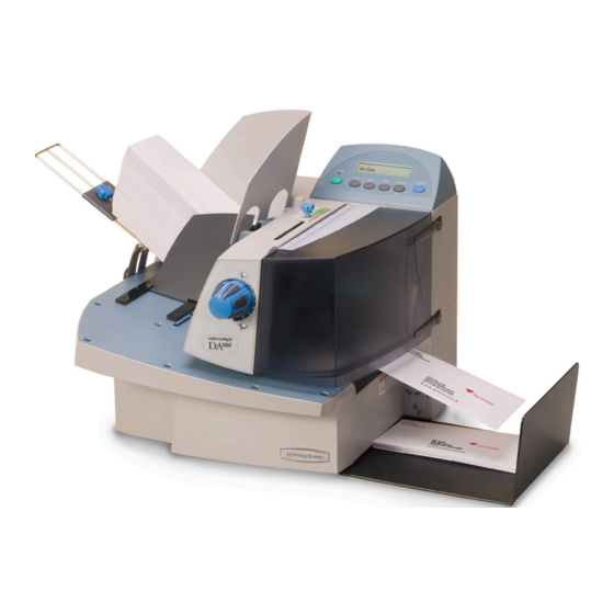
DA80F and DA95F AddressRight Fixed Head Printers ™ DA80F (WF81) DA95F (WF96) Service Manual... - Page 2 All rights reserved. This book may not be reproduced in whole or in part in any fashion or stored in a retrieval system of any type or transmitted by any means, electronically or mechanically, without the express written permission of Pitney Bowes Inc. We have made every reasonable effort to assure the accuracy and usefulness of this manual, how- ever, we cannot assume responsibility for errors or omissions or liability for the misuse or misappli- cation of our products.
-
Page 3: Table Of Contents
4.4 Error Codes ................4-9 4.5 Print Samples for Troubleshooting .......... 4-12 4.6 Feeding Issues ................ 4-14 4.7 Printing Issues ................. 4-19 4.8 Display Issues ................. 4-23 4.9 Miscellaneous Issues .............. 4-23 DA80F/DA95F AddressRight™ Printers Service Manual (SV61962 Rev. A) - Page 4 5.23 Lower Sensor Receiver Assembly ......... 5-41 5.24 Feeder Top Sensor (Emitter) Assembly ......... 5-42 5.25 “H Block” Roller (Media Separator) ........5-43 5.26 Feed Belts and Rollers ............5-44 5.27 Motor/Drive Assembly............5-46 DA80F/DA95F AddressRight™ Printers Service Manual (SV61962 Rev. A)
- Page 5 6.5 Leveling the Print Head Assembly to Deck....... 6-5 6.6 Adjustable Thickness Knob and Eccentric Sprockets ....6-6 Chapter 7 - Maintenance Procedures 7.1 General Maintenance ..............7-1 7.2 Specific Maintenance ............... 7-2 DA80F/DA95F AddressRight™ Printers Service Manual (SV61962 Rev. A)
- Page 6 Appendix D – Print Head Alignment D.1 Reason for this Appendix ............D-1 D.2 Print Head Alignment Procedure..........D-2 Appendix E – Printing Standards E.1 USPS® Delivery Point Barcode (DPBC) ........E-1 E.2 USPS® PLANET Code Barcode ..........E-3 Index ................DA80F/DA95F AddressRight™ Printers Service Manual (SV61962 Rev. A)
-
Page 7: Purpose Of This Manual
1 • Introduction This manual contains instructions for troubleshooting and site repair of DA80F 1.1 Purpose of (WF81) and DA95F (WF96) AddressRight™ fixed head printers. It also includes this Manual complete product specifications and a section on theory for training purposes. -
Page 8: Book Organization
5 mA is dan ger ous —you may jump back and be injured; 12 mA causes hand muscles to con tract, so you can not free your self; 24 mA has proven fatal; and 100 mA (1/10 amp) is likely to be fa tal. DA80F/DA95F AddressRight™ Printers Service Manual (SV61962 Rev. A) - Page 9 Never jerk or twist! g. Put the weight down by keeping your low back bowed in. h. Keep your feet apart, staggered if possible. Wear shoes with non-slip soles. Get help if you need it. DA80F/DA95F AddressRight™ Printers Service Manual (SV61962 Rev. A)
- Page 10 When han- dling a board, try not to touch the connector; when handling a chip, try not to touch the pins. DA80F/DA95F AddressRight™ Printers Service Manual (SV61962 Rev. A)
-
Page 11: Product Description
2 • Specifications The DA80F (WF81) and DA95F (WF96) ink jet printers are fixed head type 2.1 Product desktop models used to print addresses, graphics and other information, in Description black ink and spot color on a wide range of material sizes, construction and composition. - Page 12 ANSI and ISO Standards is no more than 75 dB(A). DA95F The sound pressure level at the operator’s position for this equipment as mea- sured in any mode using ANSI and ISO Standards is no more than 76 dB(A). DA80F/DA95F AddressRight™ Printers Service Manual (SV61962 Rev. A)
-
Page 13: Print Specifications
Address Placement • Barcode Characteristics • Print Quality Barcode Printing Position The printer can print a barcode in one of three positions: • Above the address block • Below the address block DA80F/DA95F AddressRight™ Printers Service Manual (SV61962 Rev. A) - Page 14 Bowes Envelope Designer Plus software allows you to place a FIM graphic on the envelope. You can obtain photo-ready graphics directly from the USPS (the Envelope Designer software itself can not create the FIM barcode graphic). DA80F/DA95F AddressRight™ Printers Service Manual (SV61962 Rev. A)
- Page 15 Effective Print Area The printable width is the width of the piece measured from the right side of Specifications the piece of mail. The printable height is 1.5" (38mm) for the DA80F and 3” (76mm) fro the DA95F. NOTES: •...
- Page 16 Cartridges are operator replaceable. The ink supply cartridges for the Specifications DA80F and DA95F are the same ones used on their predecessor models (see table on page 1-1). The table below lists some common order num- bers for replacement cartridges. For a complete list of ink cartridges, go to http://www.pb.com/supplies.
-
Page 17: Material Specifications
Max. height (length) 15.5" (393 mm) 15.5" (393 mm) Min. thickness 0.003" (0.08 mm) 0.003" (0.08 mm) Max. thickness 0.25" (6.3 mm) 0.50" (12.7 mm) Input Feeder Capacity DA80F/DA95F: 500 #10 or DL Envelopes DA80F/DA95F AddressRight™ Printers Service Manual (SV61962 Rev. A) - Page 18 Sheet stock may consist of 20 to 28 lb. (75 to 105g/m ) bond as well as 60 to 80 lb. (220 to 300g/m ) coated stock. The size and thickness con- straints specified above apply. DA80F/DA95F AddressRight™ Printers Service Manual (SV61962 Rev. A)
- Page 19 Material shall be tested with short edge leading. 2. Raise the clipboard until any portion of the stack begins to slide. The height to length ratio of the clipboard is the % slope. . DA80F/DA95F AddressRight™ Printers Service Manual (SV61962 Rev. A)
- Page 20 Postcard #3 165mm 102mm 127mm (5 inches) Postcard #4 183mm 100mm when run through the 14" (356mm) 15.5" (394mm) Maximum Paper Size printer in their usual orientation. 2-10 DA80F/DA95F AddressRight™ Printers Service Manual (SV61962 Rev. A)
-
Page 21: Chapter 3 - Theory
3 • Theory The DA80F (three print heads) and DA95F (six print heads) are fixed head, 3.1 Changes ink jet desktop printers. The DA80F (WF81) and DA95F (WF96) printers are From Earlier based on the previous Pitney Bowes fixed head printers (DA400 and DA950, Models respectively). -
Page 22: Printer Architecture
Operator Display Input Text Power Universal Power User Interface Supply System Feeder Controller Transport Motion Control Communications Head Management Ethernet Busy/Error Figure 3-1 Printer System Functional Architecture DA80F/DA95F AddressRight™ Printers Service Manual (SV61962 Rev. A) - Page 23 30.000 Piece 1 Piece 3 Piece 2 -1.5 10.000 -10.000 -2.5 0.0000 0.1000 0.2000 0.3000 0.4000 0.5000 0.6000 0.7000 Material #10 Envelope Time Model WF96 Figure 3-3 DA95F (WF96) Printer Timing Diagram DA80F/DA95F AddressRight™ Printers Service Manual (SV61962 Rev. A)
- Page 24 • Prints a test piece when OFF LINE. Test Env • Prints a report for specific menu items. NOTE: See Appendix A, Printer Control Panel Menus for a full explanation of all the menu options. DA80F/DA95F AddressRight™ Printers Service Manual (SV61962 Rev. A)
-
Page 25: Operating Sequence
The media is captured between the exit roller and the exit idler roller where it is ejected from the printer. In the DA95F, an exit sensor captures the piece exit data. This process is repeated until all the records in the file are printed. DA80F/DA95F AddressRight™ Printers Service Manual (SV61962 Rev. A) - Page 26 3 • Theory DA80F/DA95F AddressRight™ Printers Service Manual (SV61962 Rev. A)
-
Page 27: Chapter 4 - Troubleshooting/Diagnostics
4-14 for further actions, including part removal/ replacement. Standard Printer Setup Procedures (see DA80F or DA95F Operator Guides for specific instructions) 1. Verify that the output stack is not backing up into paper path 2. Recheck standard feeder setup procedures: a. -
Page 28: Block Diagrams
Paper Sensor Emitter Transport Motor Receiver Exit Sensor Emitter Receiver PB Stacker Hi Speed Feeder Shaft Feeder Encoder Encoder Feeder Motor Emitter Receiver Universal Feeder Sensor Power Supply External Feeder WS80001 Power Input DA80F/DA95F AddressRight™ Printers Service Manual (SV61962 Rev. A) - Page 29 Troubleshooting/Diagnostics • 4 4.2 Block Diagrams Figure 4-3 DA80F (WF81)/DA95F (WF96) Printer Detailed Block Diagram DA80F/DA95F AddressRight™ Printers Service Manual (SV61962 Rev. A)
-
Page 30: Main Controller Board Diagnostics
4 • Troubleshooting/Diagnostics 4.3 Main Controller Board Diagnostics Figure 4-3 Main Controller Board Mounted in DA80F (WF81) Printer Figure 4-4 Main Controller Board Mounted in DA95F (WF96) Printer DA80F/DA95F AddressRight™ Printers Service Manual (SV61962 Rev. A) - Page 31 DA80F CR11 and DA95F] J23 (Input Power) J11 (for W98X Series Stacker) J15 (Feeder Motor Sensor, Feeder Motor Encoder Sensor, DA95F) Figure 4-5 Main Controller Board With Service-Related Components Called Out DA80F/DA95F AddressRight™ Printers Service Manual (SV61962 Rev. A)
- Page 32 Feeder Motor DA80F only Transport Motor Exit Sensor Receiver DA95F only Exit Sensor Emitter DA95F only Not used currently Feeder Motor Encoder DA80F only Paper Sensor Emitter Paper Sensor Receiver Shaft Encoder DA80F/DA95F AddressRight™ Printers Service Manual (SV61962 Rev. A)
- Page 33 (indicates when printer is feeder motor printing over-current detected) CR12 Transport Motor Current LED is lit from LED stays Limit time-to-time lit (indicates when printer is feeder motor printing over-current detected) DA80F/DA95F AddressRight™ Printers Service Manual (SV61962 Rev. A)
- Page 34 TP38 40V ±5% Input from power supply TP39 Ground Ground for 3.3V measurement TP26 Ground Ground for 1.5V measurement TP28 Ground Ground for 40V measurement TP40 Ground Ground for 5V measurement TP37 DA80F/DA95F AddressRight™ Printers Service Manual (SV61962 Rev. A)
-
Page 35: Error Codes
05 No J33/Transport Sensor Cable 2. Replace transport sensor Newport Board = print head board 11 Newport Board X Not Present 1. Check all cables 2. Replace print head board “X” 3. Replace main board DA80F/DA95F AddressRight™ Printers Service Manual (SV61962 Rev. A) - Page 36 Remove material from stacker Stacker Full Remove jam from transport (also Transport Stall Err see troubleshooting tables) Clear all material from paper path Unknown Error and resume if message reoccurs call service 4-10 DA80F/DA95F AddressRight™ Printers Service Manual (SV61962 Rev. A)
- Page 37 If the simple job runs OK, there maybe an issue with the initial job. Send the problem job to Pitney Bowes Engineering for escalation resolution. 3. If the simple job and problem job both have issues, check all main board connectors.
-
Page 38: Print Samples For Troubleshooting
Move barcode location on (multiple print heads mailpiece so barcode marks used to print a bar- are not printed across mul- code) tiple print heads Shadow Print Do standard printer setup (see page 4-1) 4-12 DA80F/DA95F AddressRight™ Printers Service Manual (SV61962 Rev. A) -
Page 39: Troubleshooting
Troubleshooting/Diagnostics • 4 4.5 Print All 3 versions of FIM Barcode (USPS) Samples for Return Address Troubleshooting Figure 4-6 Sample Envelope Printed with a Variety of Options DA80F/DA95F AddressRight™ Printers Service Manual (SV61962 Rev. A) 4-13... -
Page 40: Feeding Issues
It is possible for material to wind up in the machine base cavity. When this happens, you may encounter strange noises, blocked sensors, and other symptoms not readily visible when you are troubleshooting the printer. 4-14 DA80F/DA95F AddressRight™ Printers Service Manual (SV61962 Rev. A) - Page 41 Error on LCD setup minimum spec, or material is Display translucent, making the ma- chine think that the paper is shorter than it is. DA80F/DA95F AddressRight™ Printers Service Manual (SV61962 Rev. A) 4-15...
- Page 42 Broken clutch Replace the clutch Broken belt Replace the belt Bad feed motor Replace bad motor 4-16 DA80F/DA95F AddressRight™ Printers Service Manual (SV61962 Rev. A)
- Page 43 Check the voltages on the Main Board. Slowly turn the transport belt and check for a transition when checking the voltage on the encoder. Bad Motor Replace bad motor Bad Main Board Replace Main Board DA80F/DA95F AddressRight™ Printers Service Manual (SV61962 Rev. A) 4-17...
- Page 44 (WF9S), or soft cotton cloth, replace if the Feeding Issues necessary tables on these pages will NOT apply. Please refer instead to the documentation sup- plied with your feeder. 4-18 DA80F/DA95F AddressRight™ Printers Service Manual (SV61962 Rev. A)
-
Page 45: Printing Issues
(when there is no physical sign that the print head driver board is damaged). See sec- tion 5.15 for WF81 or section 5.36 for WF96. DA80F/DA95F AddressRight™ Printers Service Manual (SV61962 Rev. A) 4-19... - Page 46 Print heads not level to Level print heads (see section 6.4 for deck (floor) WF81 and section 6.5 for WF96) Exit idler rollers dirty Clean rollers with water to remove ink 4-20 DA80F/DA95F AddressRight™ Printers Service Manual (SV61962 Rev. A)
- Page 47 ESC Sequence. Remove the ESC Sequence from the address. Incorrect Software Driver Use correct AddressRight driver. Garbage print Wrong Symbol Set Select correct Symbol Set from print- selected in printer ers Setup Menu. DA80F/DA95F AddressRight™ Printers Service Manual (SV61962 Rev. A) 4-21...
- Page 48 Menu or Software Control Panel) the justing transport speed down or increase the between-piece feed gap until the feeder does not stop regularly during the job. Proper adjustment improves machine throughput and provides longer lasting operation. 4-22 DA80F/DA95F AddressRight™ Printers Service Manual (SV61962 Rev. A)
-
Page 49: Display Issues
Connect J23 (provides power to disconnected board from power supply) Fuse blown in Power Replace power supply - no service Supply replaceable parts inside (see sec- tion 5.20 for WF81 or section 5.41 for WF96) DA80F/DA95F AddressRight™ Printers Service Manual (SV61962 Rev. A) 4-23... - Page 50 4 • Troubleshooting/Diagnostics 4-24 DA80F/DA95F AddressRight™ Printers Service Manual (SV61962 Rev. A)
-
Page 51: List Of Procedures
5 • Removal and Replacement This chapter contains parts removal instructions and is divided into two sec- 5.1 List of tions; one for the DA80F model and one for the DA95F model. procedures Tools Required • Ball end square (quadrax) drives. Sizes used:... - Page 52 5.36 Print Head Cables and Print Head Boards ......5-59 5.37 Belt Drive Assembly............... 5-67 5.38 Media Belts ................5-69 5.39 Encoder Assembly ..............5-71 5.40 Drive Belt/Motor Assembly ............ 5-74 5.41 Power Supply ................ 5-75 DA80F/DA95F AddressRight™ Printers Service Manual (SV61962 Rev. A)
-
Page 53: Rear Cover And Keyboard/Lcd Display Board
Keyboard Overlay Screws Under Overlay (dotted circles) 6. Support the keyboard/LCD board from inside the rear chassis assembly, then unfasten the three screws securing the keyboard/LCD board. 7. Reinstall in reverse order. DA80F/DA95F AddressRight™ Printers Service Manual (SV61962 Rev. A) -
Page 54: Main Processor Board
(behind board) to chassis. Remove the processor board and metal plate together. Screws that hold Board and Ground Plate to Chassis (white circles) Main Processor Board with Ground Plate Behind DA80F/DA95F AddressRight™ Printers Service Manual (SV61962 Rev. A) - Page 55 (J1, J2, J3) on the main processor board. Make sure each cable is aligned straight before fully seating; otherwise, some pins may touch and cause damage to the print head (Newport) boards inside the print head assembly upon powering up. DA80F/DA95F AddressRight™ Printers Service Manual (SV61962 Rev. A)
- Page 56 You may have to bias the of top of the wrench towards the en- coder base to find the set screw while turning the shaft. Insert Allen Wrench into Exposed Hole Transport Roller Pulley (circled) DA80F/DA95F AddressRight™ Printers Service Manual (SV61962 Rev. A)
-
Page 57: Encoder Assembly
You also need to have on hand the special encoder alignment bushing tool (PN# WS71001 Continue with step 9. Backing Plate <-Two Screws Holding Backing Plate (Circled) DA80F/DA95F AddressRight™ Printers Service Manual (SV61962 Rev. A) - Page 58 “Transport Stall Err”, then there is an issue with the encoder. First start by ensuring that the encoder is plugged in and restart the pro- cess again if needed. 16. If functioning properly, reinstall remaining covers. DA80F/DA95F AddressRight™ Printers Service Manual (SV61962 Rev. A)
-
Page 59: Paper Top Sensor Assembly (Emitter)
Sensor Assembly Screw for Assembly 5. Reinstall in reverse order. NOTE: Replacing the paper bottom sensor assembly will require an adjustment. Refer to section 6.3 Feeder Sensor Test and Calibration for more information. DA80F/DA95F AddressRight™ Printers Service Manual (SV61962 Rev. A) -
Page 60: Feeder Sensor Assembly (Emitter And Receiver)
Circled in White 5. Reinstall in reverse order. NOTE: Replacing the feeder sensor assembly will require an adjustment. Refer to section 6.3 Feeder Sensor Test and Calibration for more infor- mation. 5-10 DA80F/DA95F AddressRight™ Printers Service Manual (SV61962 Rev. A) -
Page 61: Front Bottom Cover Assembly
Unfasten the three screws on the bottom of the front bottom cover assembly. Front Bottom Cover Assembly Three Screws, Circled 5. Pull the cover away from the printer. 6. Reinstall in reverse order. DA80F/DA95F AddressRight™ Printers Service Manual (SV61962 Rev. A) 5-11... -
Page 62: Transport Timing Belt
3. Slide auto-tensioner back to release tension on belt, then re-tighten screw. Slowly walk the belt off the feed pulley assembly. 4. Install new belt. Loosen screw, tension new belt, then re-tighten screw. 5. Replace cover. 5-12 DA80F/DA95F AddressRight™ Printers Service Manual (SV61962 Rev. A) -
Page 63: Feed Motor Timing Belt
3. Slide auto-tensioner back to release tension on belt, then re-tighten screw. Slowly walk the belt off the feed pulley assembly 4. Install new belt. Loosen screw, tension new belt, then re-tighten screw. 5. Reinstall main board and rear cover. DA80F/DA95F AddressRight™ Printers Service Manual (SV61962 Rev. A) 5-13... -
Page 64: Feed Roller Pulley And Feed Roller Assembly
4. Loosen top screw and unfasten bottom screw on brake assembly. Swing brake assembly to the side. Pop bearings out and remove break assembly. Top Screw (loosen) Brake Assembly Bottom Screw (remove) 5-14 DA80F/DA95F AddressRight™ Printers Service Manual (SV61962 Rev. A) -
Page 65: Roller Assembly
8. Reinstall in reverse order. NOTE: When replacing the tires on the feed roller assembly, check that the cut of the crepe tires runs so the smoother cut is running forward. DA80F/DA95F AddressRight™ Printers Service Manual (SV61962 Rev. A) 5-15... - Page 66 Screws for Power Supply Partial Removal of Access Cover (Circled) Power Supply 5. Unplug encoder cable (J26) from feed motor and cut cable tie. Encode Cable and Cable Tie to Feed Motor 5-16 DA80F/DA95F AddressRight™ Printers Service Manual (SV61962 Rev. A)
- Page 67 NOTE: Connect encoder cable on new motor before inserting motor into place. Push the cable through the openings in the rear chassis assembly. Hook up the feed motor encoder cable to the processor board at connec- tor J31. DA80F/DA95F AddressRight™ Printers Service Manual (SV61962 Rev. A) 5-17...
-
Page 68: Transport Motor Assembly
Cover (Circled) 4. Unfasten the four screws securing the transport motor assembly to the front plate assembly. Keep the back of the motor from dropping. Four Screws Holding Transport Motor Assembly 5-18 DA80F/DA95F AddressRight™ Printers Service Manual (SV61962 Rev. A) -
Page 69: Motor Assembly
6. When positioning the new motor pulley on the front plate assembly, make sure you leave a 0.200” space between the pulley and motor face. Motor Face Pulley 7. Reinstall in reverse order. DA80F/DA95F AddressRight™ Printers Service Manual (SV61962 Rev. A) 5-19... -
Page 70: H-Block Assembly (Media Separators)
3. Turn the “H” block over and unfasten the screw securing the separator finger on the “H” block. Separator Fingers H Block Flipped Showing Screws on “H” Block for Separator Fingers (Circled) 5. Reinstall in reverse order. 5-20 DA80F/DA95F AddressRight™ Printers Service Manual (SV61962 Rev. A) -
Page 71: Print Head Cables And Print Head Boards
4. Unfasten two screws from clamp above main board to release print head ribbon cable stiffener. Clamp for Print Head Ribbon Cable Stiffener (Screws Circled) DA80F/DA95F AddressRight™ Printers Service Manual (SV61962 Rev. A) 5-21... - Page 72 6. Remove the print head assembly and pull print cables through opening. Opening for Cables Print Head Assembly 7. Remove four screws (small allen size) for print head metal cover. Print Head Cover Screws for Print Head Cover (circled) 5-22 DA80F/DA95F AddressRight™ Printers Service Manual (SV61962 Rev. A)
- Page 73 10. Pull out slightly the tan locking piece on the edge of the connector with your fingernail and simply remove cable (uses zero insertion force). Removing Cable from Tan Locking Edge of Print Head Board Piece Connector DA80F/DA95F AddressRight™ Printers Service Manual (SV61962 Rev. A) 5-23...
- Page 74 (Circled) 12. Insert a screwdriver between the retainer plate and print head stall and gently pry the retainer plate outwards. Retainer Plate 13. Remove print head (Newport) board. Print Head Board 5-24 DA80F/DA95F AddressRight™ Printers Service Manual (SV61962 Rev. A)
- Page 75 The engagement tabs on the other side of the plate will “snap” into position on the opposite side of the cartridge stall. Tighten the screws lightly once plate has been snapped into position. DA80F/DA95F AddressRight™ Printers Service Manual (SV61962 Rev. A) 5-25...
- Page 76 19. Route new cables through black stiffener saved from the original print head cables and clamp above main board. Use the two screws to clamp down on the cable stiffener. Clamp for Print Head Ribbon Cable Stiffener (Screws Circled) 5-26 DA80F/DA95F AddressRight™ Printers Service Manual (SV61962 Rev. A)
- Page 77 (Newport) boards upon powering up. 22. Power up the machine. Do a print test from the control panel to confirm proper operation of print heads. DA80F/DA95F AddressRight™ Printers Service Manual (SV61962 Rev. A) 5-27...
-
Page 78: Entry Idler Roller Arm
5. Remove the e-ring from the shaft and entry idler roller from the shaft. NOTE: The nylon washer between the roller and the entry idler arm as- sembly may fall off when the roller is removed. E-ring Entry Idler Rollers 5-28 DA80F/DA95F AddressRight™ Printers Service Manual (SV61962 Rev. A) - Page 79 B. Adjust the lower shaft using the two screws at either end (see step 6 above) until you reach the proper height. Idler Roller Shaft Lower Shaft Idler Roller Height for Adjustment Transport (must be between Roller 0.170” and 0.210”) DA80F/DA95F AddressRight™ Printers Service Manual (SV61962 Rev. A) 5-29...
-
Page 80: A Feed Deck
3. Unfasten two thumbscrews for extension bin and remove bin. Thumbscrews for Extension Bin (circled) 4. Unfasten screw on side of deck and on top (see figures below). Screw on Side of Deck Screw on Feed Deck 5-30 DA80F/DA95F AddressRight™ Printers Service Manual (SV61962 Rev. A) - Page 81 6. Remove three feed deck mounting screws on front of chassis. Feed Deck Screws on Front Chassis (Circled) 7. Lift out feed deck. Feed Deck Removed 8. Reinstall in reverse order. DA80F/DA95F AddressRight™ Printers Service Manual (SV61962 Rev. A) 5-31...
-
Page 82: B Front Plate Assembly
Pop bearings out and remove break assembly. Top Screw (loosen) Brake Assembly Bottom Screw (remove) 6. Remove two timing pulleys (two set screws per each) and pulley spacers. Timing Pulleys 5-32 DA80F/DA95F AddressRight™ Printers Service Manual (SV61962 Rev. A) - Page 83 NOTE: Make certain to set the tensioner on the transport timing belt (see section 5.9). TIP: Work the printer motor harness through the main chassis before the front plate assembly is reinstalled. DA80F/DA95F AddressRight™ Printers Service Manual (SV61962 Rev. A) 5-33...
-
Page 84: Transport (Metal Grit) Roller
Rear Chassis Side of Roller (under Encoder) 5. Remove transport (metal grit) roller. Transport (Metal Grit) Roller 5-34 DA80F/DA95F AddressRight™ Printers Service Manual (SV61962 Rev. A) - Page 85 NOTE: Make certain to set the tensioner on the transport timing belt (see section 5.9) and feed motor timing belt (see section 5.10). TIP: Work the printer motor harness through the main chassis before the front plate assembly is reinstalled. DA80F/DA95F AddressRight™ Printers Service Manual (SV61962 Rev. A) 5-35...
-
Page 86: Exit (Rubber) Roller
NOTE: Make certain to set the tensioner on the transport timing belt (see section 5.9). TIP: Work the printer motor harness through the main chassis before the front plate assembly is reinstalled. 5-36 DA80F/DA95F AddressRight™ Printers Service Manual (SV61962 Rev. A) -
Page 87: Power Supply
6. Unplug two harnesses (see below) to separate power supply from chassis. Cover Removed, Harness Connectors Circled 7. Unfasten four screws holding power supply to mounting panel and re- move supply. 8. Reinstall in reverse order. DA80F/DA95F AddressRight™ Printers Service Manual (SV61962 Rev. A) 5-37... -
Page 88: Print Head Access Door
3. Push down with fingers on metal hinge bracket and remove door. Door 3. Reinstall in reverse order, but make sure you push the hinge bracket to- wards the operator side of machine when installing the door. 5-38 DA80F/DA95F AddressRight™ Printers Service Manual (SV61962 Rev. A) -
Page 89: Rear Cover/Side Guides
5. Pull the side guides (sliding fences) wide open on the feeder assembly. Optionally, remove the side guides should they hinder the removal of the feeder deck (two screws per side guide). DA80F/DA95F AddressRight™ Printers Service Manual (SV61962 Rev. A) 5-39... - Page 90 Side Guides Removed 8. Locate and remove from the inside of the feeder assembly the four screws that secure the rear cover. Remove the rear cover. Screws For Rear Cover (Circled) 5-40 DA80F/DA95F AddressRight™ Printers Service Manual (SV61962 Rev. A)
-
Page 91: Lower Sensor Receiver Assembly
5. Pull the sensor harness through the hole in the bottom of the feeder as- sembly. 6. Reinstall in reverse order. NOTE: Replacing the feeder lower sensor assembly will require an ad- justment. Refer to section 6.3 Feeder Sensor Test and Calibration for more information. DA80F/DA95F AddressRight™ Printers Service Manual (SV61962 Rev. A) 5-41... - Page 92 Top Sensor Emitter 6. Reinstall in reverse order. NOTE: Replacing the feeder top sensor assembly will require an adjust- ment. Refer to section 6.3 Feeder Sensor Test and Calibration for more information. 5-42 DA80F/DA95F AddressRight™ Printers Service Manual (SV61962 Rev. A)
-
Page 93: H Block" Roller (Media Separator)
Shoulder Screws Shoulder Removed “H” Block Roller Screw 3. Reinstall in reverse order. NOTE: The installation of the new assembly and may require a strong push down on the H block roller. DA80F/DA95F AddressRight™ Printers Service Manual (SV61962 Rev. A) 5-43... -
Page 94: Feed Belts And Rollers
5. The tires and feed belts may be removed by pulling them from the hubs. Tire Tires 3mm Belt 3mm Belt 5-44 DA80F/DA95F AddressRight™ Printers Service Manual (SV61962 Rev. A) - Page 95 Place 0.010” shim between tensioner and pulley when reinstalling upper shaft. Pulley Shim Tensioner B. Gap Between Pulley and Motor Face Place 0.150” shim between pulley and motor face when reinstalling the lower drive shaft. Motor Face Pulley DA80F/DA95F AddressRight™ Printers Service Manual (SV61962 Rev. A) 5-45...
- Page 96 Screws Motor Assembly the next page when re-installing shafts and pulleys. Screws Feed Roller Motor Assembly Assembly Encoder Disc and Sensor 5-46 DA80F/DA95F AddressRight™ Printers Service Manual (SV61962 Rev. A)
-
Page 97: Motor/Drive Assembly
Place 0.010” shim between tensioner and pulley when reinstalling upper shaft. Pulley Shim Tensioner B. Gap Between Pulley and Motor Face Place 0.150” shim between pulley and motor face when reinstalling the lower drive shaft. Motor Face Pulley DA80F/DA95F AddressRight™ Printers Service Manual (SV61962 Rev. A) 5-47... -
Page 98: Printer Top Cover
Two Screws Holding Shock Support Arm 2. While holding cover, unfasten two screws at either end where cover at- taches to chassis. Remove cover. Screws (Circled) Holding Top Cover to Chassis 5-48 DA80F/DA95F AddressRight™ Printers Service Manual (SV61962 Rev. A) -
Page 99: Front Cover And Keyboard/Lcd Display Board
Do NOT rest the printer on the cover side that has the hand held because the cover may crack from the weight of the printer. Front Cover Screws for Front Cover (circled) 8. Pull the cover away from the printer. DA80F/DA95F AddressRight™ Printers Service Manual (SV61962 Rev. A) 5-49... - Page 100 11. While supporting the keyboard/LCD board from inside the rear chassis assembly, unfasten the three screws securing the keyboard/LCD board. 12. Reinstall in reverse order. Remember to fasten the green ground strap removed in step 6. 5-50 DA80F/DA95F AddressRight™ Printers Service Manual (SV61962 Rev. A)
-
Page 101: Rear Cover And Processor Board
Do NOT rest the printer on the cover side that has the hand held because the cover may crack from the weight of the printer. Rear Cover Screws for Rear Cover (circled) DA80F/DA95F AddressRight™ Printers Service Manual (SV61962 Rev. A) 5-51... -
Page 102: Rear Cover And Processor Board
11. Unfasten the three screws (yellow circles in figure below) securing the processor board to metal ground plate and remove board. Main Processor Board Screws that hold Board to Ground Plate (yellow circles) 5-52 DA80F/DA95F AddressRight™ Printers Service Manual (SV61962 Rev. A) - Page 103 (J1 to J6) on the main processor board. Make sure each cable is aligned straight before fully seating; otherwise, some pins may touch and cause damage to the print head (Newport) boards inside the print head assembly upon powering up. DA80F/DA95F AddressRight™ Printers Service Manual (SV61962 Rev. A) 5-53...
-
Page 104: Paper Sensor And Sensor Bar
7. If replacing the sensor bar, unfasten the four screws (two on either end) that attach the sensor bar to the lift brackets. Lift to remove the sensor bar. Screws Screws Sensor Bar Paper Sensor and Sensor Bar 8. Reinstall in reverse order. 5-54 DA80F/DA95F AddressRight™ Printers Service Manual (SV61962 Rev. A) -
Page 105: Entry Roller Support Assembly
(see figure below). 5. Peel the o-ring off the roller. O-Ring Entry Idler Roller Screws for Entry Idler Roller Idler Roller Pivot Arm 7. Reinstall in reverse order. DA80F/DA95F AddressRight™ Printers Service Manual (SV61962 Rev. A) 5-55... -
Page 106: Intermediate Idler Rollers Assembly
Assembly Intermediate Idler Rollers Assembly (Circled) Bearings Springs Intermediate Idler Rollers Assembly Removed 4. Slide rollers off of shaft 5. Reinstall in reverse order. Be careful not to loose the springs. 5-56 DA80F/DA95F AddressRight™ Printers Service Manual (SV61962 Rev. A) -
Page 107: Idler Roller Support ("Module A") Assembly
Idler Roller for “Module A” Removed 3. Unfasten the two screws (one on either side) holding each idler roller to its idler roller arm and remove idler roller. 4. Reinstall in reverse order. DA80F/DA95F AddressRight™ Printers Service Manual (SV61962 Rev. A) 5-57... -
Page 108: Idler Roller Support ("Module B") Assembly
Idler Roller for “Module B” With Exit Sensor Emitter 4. Unfasten the two screws (one on either side) holding each idler roller to its idler roller arm and remove idler roller. 5. Reinstall in reverse order. 5-58 DA80F/DA95F AddressRight™ Printers Service Manual (SV61962 Rev. A) -
Page 109: Print Head Cables And Print Head Boards
Old Style Print Head Cable - In addition, loosen (but do not remove) the screws holding the metal bar for the grounding shield. Wire Management Device Metal Bar and Screws (old for Print Head Cables Style Print Head Cables) DA80F/DA95F AddressRight™ Printers Service Manual (SV61962 Rev. A) 5-59... - Page 110 B. Remove print head assembly with print head cables dangling. Top Print Head Shaft Philips Head Screw for Pivot (circled) 5-60 DA80F/DA95F AddressRight™ Printers Service Manual (SV61962 Rev. A)
- Page 111 Head Board Piece Connector 11. Loosen the two star screws on the print head board about four turns (but do not remove). Print Head Boards (aka “Newport boards”) Star Screws (Circled) DA80F/DA95F AddressRight™ Printers Service Manual (SV61962 Rev. A) 5-61...
- Page 112 (see figure, below right). This is critical for proper print head alignment. Print Head Stall <--Three Screws (Circled) Locating Holes --> for Stall (Circled) Print Head Stall Print Head Board 5-62 DA80F/DA95F AddressRight™ Printers Service Manual (SV61962 Rev. A)
- Page 113 (one screw). Make sure there is enough slack (see right figure). A very slight overlap of cables is OK when in final position. Clamping Mechanism Tape Screw Cable Slack (circled) DA80F/DA95F AddressRight™ Printers Service Manual (SV61962 Rev. A) 5-63...
- Page 114 Device on Back of Print Head Assembly 20. Thread print head ribbon cables through black stiffener and route assem- bly through access hole to main board. Black Stiffener Access--> Holes to Main Board (circled) 5-64 DA80F/DA95F AddressRight™ Printers Service Manual (SV61962 Rev. A)
- Page 115 (plastic clips) and allow enough slack on cables for print head to travel to opposite side of printer. Wire Management Device Slack in Print Head Cables (Circled) for Print Head Cables DA80F/DA95F AddressRight™ Printers Service Manual (SV61962 Rev. A) 5-65...
- Page 116 Leveling the Print Head Assembly to Deck adjustment. 24. Power up the machine. Do a print test from the control panel to confirm proper operation of print heads. 5-66 DA80F/DA95F AddressRight™ Printers Service Manual (SV61962 Rev. A)
-
Page 117: Belt Drive Assembly
Do it slowly so as not to snag any of the cable assemblies. Clip the tie wrap at bottom of base holding cables. DA80F/DA95F AddressRight™ Printers Service Manual (SV61962 Rev. A) 5-67... - Page 118 NOTE: When reinstalling the belt drive assembly on the base assembly, remove the access pan cover so the cables can be threaded through the appropriate openings in the base to connect with the processor board. 5-68 DA80F/DA95F AddressRight™ Printers Service Manual (SV61962 Rev. A)
-
Page 119: Media Belts
Loosen those two screws to allow the floor to open up on the other end. Loosen Screw Loosen Screw Remove Screws Remove Entry Screws Roller DA80F/DA95F AddressRight™ Printers Service Manual (SV61962 Rev. A) 5-69... - Page 120 (this tightens the belt on that side). Likewise, if the belt is already very tight you may turn the customer side adjustment screw counter-clockwise instead. C. Often a combination of adjusting both the drive side and customer side screws is necessary. 5-70 DA80F/DA95F AddressRight™ Printers Service Manual (SV61962 Rev. A)
-
Page 121: Encoder Assembly
Insert Allen Wrench into Exposed Hole Drive Roller Pulley (circled) DA80F/DA95F AddressRight™ Printers Service Manual (SV61962 Rev. A) 5-71... - Page 122 (PN# WS71001) han- dy when you remove the encoder. You will need this tool if you wind up replacing the encoder backing plate. <-Two Backing Plate Screws Holding Backing Plate (Circled) 5-72 DA80F/DA95F AddressRight™ Printers Service Manual (SV61962 Rev. A)
- Page 123 “Transport Stall Err”, then there is an issue with the encoder. First start by ensuring that the encoder is plugged in and restart the pro- cess again if needed. 16. If functioning properly, reinstall remaining covers. DA80F/DA95F AddressRight™ Printers Service Manual (SV61962 Rev. A) 5-73...
-
Page 124: Drive Belt/Motor Assembly
4 ± 0.5 Lbs. of force. Belt C. Tighten the three screws when at the proper tension. 8. Reinstall remaining components in reverse order. 5-74 DA80F/DA95F AddressRight™ Printers Service Manual (SV61962 Rev. A) -
Page 125: Power Supply
6. Unplug remaining cable harness in supply to separate supply from chassis. 7. Unfasten four screws holding power supply to mounting panel and re- move supply. 8. Reinstall in reverse order. DA80F/DA95F AddressRight™ Printers Service Manual (SV61962 Rev. A) 5-75... - Page 126 5 • Removal and Replacement DA95F (WF96) - Printer Parts Removal 5-76 DA80F/DA95F AddressRight™ Printers Service Manual (SV61962 Rev. A)
-
Page 127: List Of Adjustments
6 • Adjustments This chapter discusses adjustments for the DA80F (WF81) and DA95F 6.1 List of (WF96) fixed head printers. Adjustments Adjustments for All Models 6.2 LCD Display ................6-2 6.3 Feeder Sensor Test and Calibration ......... 6-2 DA80F (WF81) Adjustments 6.4 Leveling the Print Head Assembly to Deck (Belts) .... -
Page 128: Feeder Sensor Test And Calibration
6 • Adjustments 1. Unfasten appropriate cover to gain access to keyboard/LCD display 6.2 LCD board. For the DA80F (WF81), see section 5.2; for the DA95F (WF96), Display see section 5.29. (All Models) 2. From behind cover, use a flat-blade screwdriver to adjust the yellow pot (clockwise to increase brightness, counterclockwise to decrease bright- ness). -
Page 129: Da80F (Wf81) Adjustments
2. Turn the thickness adjustment knob to send the print head assembly to its lowest position. 3. Loosen the print head clamp knob and move the print head assembly against the chassis wall. DA80F/DA95F AddressRight™ Printers Service Manual (SV61962 Rev. A) - Page 130 5. Adjust lower shaft so print head assembly is parallel to deck. Slide the print head assembly back and forth along the shaft to verify parallelism across entire deck. 6. Tighten lower shaft. 7. Replace rear cover and front top cover. DA80F/DA95F AddressRight™ Printers Service Manual (SV61962 Rev. A)
-
Page 131: Da95F (Wf96) Adjustments
Adjust Wedge (Circled) Wedge 6. Adjust the screw so that the print head is parallel to the deck (belts). 7. Repeat steps 1- 6 to adjust the other print head assembly. DA80F/DA95F AddressRight™ Printers Service Manual (SV61962 Rev. A) -
Page 132: Adjustable Thickness Knob And Eccentric Sprockets
A light resistance is felt when the media is pulled. Verify both print head assemblies are parallel. 6. Rotate the adjustable thickness knob all the way counterclockwise up against the stop. The adjustable thickness knob will be in the 12 o’clock position. DA80F/DA95F AddressRight™ Printers Service Manual (SV61962 Rev. A) - Page 133 If the resistance on the me- dia needs to be adjusted, then redo steps 8-10 until the right tension is felt. 13. Re-install front cover, and rear cover/main processor board. DA80F/DA95F AddressRight™ Printers Service Manual (SV61962 Rev. A)
- Page 134 6 • Adjustments DA80F/DA95F AddressRight™ Printers Service Manual (SV61962 Rev. A)
-
Page 135: General Maintenance
7 • Preventive Maintenance This chapter discusses preventive maintenance for the DA80F/DA95F 7.1 General (WF81/WF96) fixed head printers. Maintenance WARNING: Unplug the printer before performing any or cleaning or maintenance. CAUTION: Clean the print head cartridge, ink surfaces and covers with plain water. Clean all rubber rollers with iso- propyl, denatured, or rubbing alcohol only. -
Page 136: Specific Maintenance
• Check the flex circuit for crushed dimples The pan assembly at the bottom of the print- Annually Pan Assembly er collects paper dust. Remove the bottom Pan Access Cover peri- odically and clean dust from the printer. DA80F/DA95F AddressRight™ Printers Service Manual (SV61962 Rev. A) -
Page 137: Appendix A - Printer Control Panel Menus And Utilities
• Includes robust help system to help you use the features. *Early-production shuttle head printers (DA5xS/DA7xxS) released with software ver- sion 1.0 have different passwords; Supervisor - 55555, Service - 32322. DA80F/DA95F AddressRight™ Printers Service Manual (SV61962 Rev. A) -
Page 138: For The Printer
*Assuming you have logged on with the appropriate password Feature/Tab Access on Control Panel Software by Logon Password (in Off line State) Logon Status Alignment Configuration Test & Preference/ Service Control Adjust Info Tab Limited Standard Supervisor Service DA80F/DA95F AddressRight™ Printers Service Manual (SV61962 Rev. A) -
Page 139: A.2 Lcd Control Panel Menu
“OFF LINE”). Exiting the LCD Menus • Press Menu until the printer LCD displays “OFF LINE”. • Press On Line to enable the printer. DA80F/DA95F AddressRight™ Printers Service Manual (SV61962 Rev. A) -
Page 140: Lcd Main Menu
7. Job Settings a. Load b. Save 8. Image Overlay a. Capture Overlay b. Clear Overlay c. Print Overlay 9. Purge Print Head 10. Ink Count a. Head 1 b. Head 2, etc. DA80F/DA95F AddressRight™ Printers Service Manual (SV61962 Rev. A) - Page 141 Automatic, Changes the orientation between automatic, E Orientation Manual (the printer acknowledges the orientation com- Control mands sent from the computer) or manual (printer uses the menu settings for orientation) DA80F/DA95F AddressRight™ Printers Service Manual (SV61962 Rev. A)
- Page 142 Italic characters mimic script (handwriting) and are used to emphasize text in an address that requires a finished, polished appearance. DA80F/DA95F AddressRight™ Printers Service Manual (SV61962 Rev. A)
- Page 143 (not in the PC print queue) and recovered as part of the you want to clear the internal buffer if you current job. want to start over with a known printer state. DA80F/DA95F AddressRight™ Printers Service Manual (SV61962 Rev. A)
- Page 144 Disabled - Does not print the captured program (such as En- overlay first, but uses the overlay for the suc- velope Designer Plus). ceeding print jobs Mostly used in a non- Windows environment. DA80F/DA95F AddressRight™ Printers Service Manual (SV61962 Rev. A)
- Page 145 LCD Setup Menu) and it must be changed relatively soon. The per- centage of ink available is calculated based on the cartridge chosen in 9. Ink Cartridge Volume in LCD Setup Menu. DA80F/DA95F AddressRight™ Printers Service Manual (SV61962 Rev. A)
-
Page 146: Lcd Setup Menu
1. Stop on Feed Error Menu Option Settings What It Does Off, Allows you to set the printer to stop when it Stop on Feed encounters any feed error. Error A-10 DA80F/DA95F AddressRight™ Printers Service Manual (SV61962 Rev. A) -
Page 147: Tip: After Changing A
“Other” feeder. (msec) again for the new set- msec incre- NOTE: This option only displays if “Pulse- tings to be recognized. ments) Off” is selected for Feeder Signal. DA80F/DA95F AddressRight™ Printers Service Manual (SV61962 Rev. A) A-11... - Page 148 (which is typically the RJ-11 connec- dress between 3 to 8 lines per record). tor used to attach a third-party conveyor, see Appendix C - Schematics. A-12 DA80F/DA95F AddressRight™ Printers Service Manual (SV61962 Rev. A)
-
Page 149: Setup Menu
1. Take printer off line. 2. On host PC, go to Settings> Control Panel>Printer. Right click on desired printer. 3. Locate print job to cancel. Right click on it; go to Document>Cancel. DA80F/DA95F AddressRight™ Printers Service Manual (SV61962 Rev. A) A-13... - Page 150 Varying the speed of the transport belt will not affect the print quality. NOTE: The maximum percent- age you can enter is dependent on the current print quality when an internal feeder is attached. A-14 DA80F/DA95F AddressRight™ Printers Service Manual (SV61962 Rev. A)
- Page 151 Normal Capacity - based on the ink used in the HP 51645A print cartridge Extended Capacity - based on the reservoir system, which is nine times the volume of the HP 51645A ink cartridge DA80F/DA95F AddressRight™ Printers Service Manual (SV61962 Rev. A) A-15...
-
Page 152: Enable, Disable
(both minimally). produce smudging. Enable, If set to “Enable”, the printer uses a random D. Nozzle Keep Disable pattern of spitting to keep nozzles clean Alive throughout the running of a job. A-16 DA80F/DA95F AddressRight™ Printers Service Manual (SV61962 Rev. A) - Page 153 0 to 31.75 seconds Allows you to specify the length of G. Break Pause (in 0.25 second incre- time the printer will pause printing Time ments) when a bundle break is detected. DA80F/DA95F AddressRight™ Printers Service Manual (SV61962 Rev. A) A-17...
- Page 154 Threshold percent incre- warning to display. ments) Enabled, Allows the printer to stop when the ink has C. Stop When Disabled been depleted (0 percent remaining). Empty A-18 DA80F/DA95F AddressRight™ Printers Service Manual (SV61962 Rev. A)
- Page 155 To print a hex dump once you’ve enabled the mode, press the Menu button to back out of the menu until the printer displays Off Line Then press On Line and send addresses to the printer. DA80F/DA95F AddressRight™ Printers Service Manual (SV61962 Rev. A) A-19...
- Page 156 You can understand the chart on above by noting the following HEX codes: HEX Code Alphanumeric Equivalent Capital A Carriage Return Line Feed Form Feed 30-39 0-9 (HEX 30 = 0, HEX 31 = 1, etc. A-20 DA80F/DA95F AddressRight™ Printers Service Manual (SV61962 Rev. A)
- Page 157 NOTE: If the TEST button is pressed, all the menu settings are printed on as many #10 envelopes as required, using 12 point Cou- rier and in the current language. DA80F/DA95F AddressRight™ Printers Service Manual (SV61962 Rev. A) A-21...
- Page 158 3. Test Display tion, or to define a new 4. Calibrate Sensors setting. a. Paper Sensor b. Exit Sensor* *DA95F only c. Feeder Sensor 5. Brand a. Pitney Bowes b. Secap A-22 DA80F/DA95F AddressRight™ Printers Service Manual (SV61962 Rev. A)
-
Page 159: Lcd Service Menu
Mod B to Sensor Allows you to modify a nominal set- +/- 0.500 inch (in ting that affects the distance from 0.001 inch incre- the sensor to the print head you are ments) aligning DA80F/DA95F AddressRight™ Printers Service Manual (SV61962 Rev. A) A-23... - Page 160 NOTE 1: Because the DA80F does not have an exit sensor, exit sensor E is not displayed on a DA80F.
- Page 161 (0-9) across the top line, while the bottom line scrolls control characters and the numbers. The test cycles twice and returns to the Service Menu. EXAMPLE: abcdefghijklmnopqrstuvwxyz 0123456789 \->!#$%&*()_+- =[]:;’<>/? 0123456789. DA80F/DA95F AddressRight™ Printers Service Manual (SV61962 Rev. A) A-25...
- Page 162 DA95F when it is configured with an external high-speed feeder. 5. Brand Submenu Option Settings What It Does Pitney Bowes, Allows you to select Pitney Bowes or Secap Brand Secap as the basis for the printer model A-26 DA80F/DA95F AddressRight™ Printers Service Manual (SV61962 Rev. A)
-
Page 163: Setting Factory Defaults (From Lcd Menu
Executive (600 dpi) tings are listed. Light Mode 3. Font Font Courier Font Size Bold Italic 4. Barcode Barcode Location Above Address Barcode (9 Digit On/Off) Off Barcode Bar Width Normal DA80F/DA95F AddressRight™ Printers Service Manual (SV61962 Rev. A) A-27... -
Page 164: Use Conveyor
120 seconds Nozzle Keep Alive Enable 11. Bundle Break Enable/Disable Disable Bundle Break Break Character Character Orientation Vertical Break Location After Address Print Break Characters Disable Break Pause Time 3.00 seconds A-28 DA80F/DA95F AddressRight™ Printers Service Manual (SV61962 Rev. A) - Page 165 Module B Adjust - Horiz Adjust 5-4 Print Head Adjust Horiz Adjust 6-5 Vert Adj: HDS 5-4 Vert Adj: HDS 6-5 Mod B to Sensor XX.XXX in 5. Brand Pitney Bowes DA80F/DA95F AddressRight™ Printers Service Manual (SV61962 Rev. A) A-29...
-
Page 166: Updating Firmware
✍ 1. Double-click on the Pitney Bowes Control Panel icon. The Addressing TIP: Firmware can be Printer Control Panel dialog appears. obtained (downloaded) from the Customer 2. -
Page 167: Subnet Mask
9. Click the Submit button. The IE window will indicate progress with an increment of byte count. NOTE: DO NOT disconnect the printer from computer or click the Submit button again until the firmware update is complete. DA80F/DA95F AddressRight™ Printers Service Manual (SV61962 Rev. A) A-31... - Page 168 Verifying Update... Bytes left xxxxxxxxx (displayed while a data integrity check is performed on the update) Update Complete Restarting printer (displayed when the download is complete is the printer is rebooted) A-32 DA80F/DA95F AddressRight™ Printers Service Manual (SV61962 Rev. A)
- Page 169 4. Install new ink cartridge(s) or remove and reinstall the existing ink cartridge(s). Follow the LCD prompts and reset ink percentage and align ink cartridges (refer to the Printer Maintenance chapter in the DA80F or DA95F Operator Guides for detailed steps if need be).
- Page 170 Appendix A • Printer Control Panel Menus and Utilities A-34 DA80F/DA95F AddressRight™ Printers Service Manual (SV61962 Rev. A)
-
Page 171: Appendix B - Printer Communications
PC. Also, you network; allows Ethernet Cable Ethernet Cable Ethernet Cable need to turn off DHCP multiple PCs to on the printer. print to it. Ethernet Port Port Port Computer Computer DAxxF continued-> DA80F/DA95F AddressRight™ Printers Service Manual (SV61962 Rev. A) - Page 172 If needed, this cable may be easily obtained from a com- puter supply retailer. DA80F/DA95F AddressRight™ Printers Service Manual (SV61962 Rev. A)
- Page 173 Printer Communications • Appendix B Communication Scenarios Figure B-1 Typical Printer Port Settings When Using Name Resolution Communications Figure B-2 Typical Configuration Screen of Printer Port Settings for Name Resolution Communications DA80F/DA95F AddressRight™ Printers Service Manual (SV61962 Rev. A)
-
Page 174: Troubleshooting Tables
If no improvement, could be hardware problem (see next section in table). Verify proper settings in Setup Menu> 5. Communications (see section A.3) against customer’s requirements. Also see section B.3 for other tests. DA80F/DA95F AddressRight™ Printers Service Manual (SV61962 Rev. A) - Page 175 Remove from hub. Replace cable with known good cable. Bad Main Board Troubleshoot main board (see sec- tion 4.2) to determine if it is bad; replace if necessary DA80F/DA95F AddressRight™ Printers Service Manual (SV61962 Rev. A)
-
Page 176: Testing Printer Communications Within A Network
IP address on the printer is correct. If it is correct, contact the customer’s IT and inform them of the duplicate IP address. The IT department should re- move the device that is causing the problem, allowing our printer to work OK. DA80F/DA95F AddressRight™ Printers Service Manual (SV61962 Rev. A) -
Page 177: If Dhcp Is Enabled And You Press
Using DCHP Settings on the Printer to Establish Communications NOTE: This procedure is normally used only in configuration scenario “D” Printer (on page B-2), when the customer requests Pitney Bowes to setup an IP Ad- Communications dress for our printer that is on a DHCP network. - Page 178 Appendix B • Printer Communications DA80F/DA95F AddressRight™ Printers Service Manual (SV61962 Rev. A)
-
Page 179: Appendix C - Schematics
The RJ-11 Accessory Port by the power switch on the printer (J12 on the ✍ Main Controller Board) allows you to connect a third-party conveyor to the DA80F printer. See Conveyor Setup in section A.4 for the LCD Menu control TIP: A Pitney Bowes W98x series stacker panel settings needed to connect an external conveyor. -
Page 180: Main Processor
Appendix C • Schematics Main Processor Board for Both Printers DA80F/DA95F AddressRight™ Printers Service Manual (SV61962 Rev. A) -
Page 181: Block Diagram
Schematics • Appendix C Block Diagram for DA80F (WF81) DA80F/DA95F AddressRight™ Printers Service Manual (SV61962 Rev. A) - Page 182 Appendix C • Schematics Block Diagram for DA95F (WF96) DA80F/DA95F AddressRight™ Printers Service Manual (SV61962 Rev. A)
-
Page 183: Appendix D - Print Head Alignment
Appendix D • Print Head Alignment In Revision A of the DA80F Operator Guide (SV61722), as well as Revisions Reason for this A and B of the DA95F Operator Guide (SV61749), the Print Head Alignment Appendix Procedure as presented in the Printer Maintenance section was incorrect because of changes in software. -
Page 184: Print Head Alignment Procedure
5. Press the plus (+) key to scroll down through the menu to the ADJUST PRINTING screen. 6. Press Enter. The PRINT HEAD ADJUST screen displays. 7. Press Enter. The VERTICAL ADJUST 1 - 2 screen displays. DA80F/DA95F AddressRight™ Printers Service Manual (SV61962 Rev. A) - Page 185 1 and 2. Select the pair of vertical lines which most closely form a straight line. In the sample below, the letter value entered would be "i". Head 1 Head 2 Head 3 DA80F/DA95F AddressRight™ Printers Service Manual (SV61962 Rev. A)
- Page 186 Head 2 necessary. Skip to step Head 3 • If the gap is not exactly .25 in (6.35 mm), go to step 25. Head 1 Head 2 Head 3 0.25” Gap DA80F/DA95F AddressRight™ Printers Service Manual (SV61962 Rev. A)
- Page 187 .35 - .25 = .1 In this example, you would increase the number on the display by .1 to 1.7 0.35 MOD TO SENSOR +LEFT 01.700 inches -RGHT DA80F/DA95F AddressRight™ Printers Service Manual (SV61962 Rev. A)
- Page 188 B. IMPORTANT: Be sure to select the menu options for Heads 4 - 5 and 5 - 6. These are the print heads contained in module B. DA80F/DA95F AddressRight™ Printers Service Manual (SV61962 Rev. A)
-
Page 189: Appendix E - Printing Standards
Appendix E • Printing Standards NAIC Certification E.1 USPS ® The DA80F and DA95F printers are equipped with firmware for printing the Delivery Point United States Postal Service (USPS) Delivery Point Barcode (DPBC). The Barcode printer is Certified by the National Address Information Center (NAIC). Certifica-... -
Page 190: Usps® Delivery Point Barcode (Dpbc
The Tilde Tilde (~~) code barcode will print on a line when the first two charac- ters in the line are two tilde tilde characters (~~) followed by the digits that rep- resent the desired barcode (see figure below). DA80F/DA95F AddressRight™ Printers Service Manual (SV61962 Rev. A) -
Page 191: Usps® Planet Code Barcode
(~#) then the digits that repre- sent the desired PLANET code (see figure below). Other valid tilde TIP: commands are: ~^ (IMBC) generic ~! Japanese 4-state DA80F/DA95F AddressRight™ Printers Service Manual (SV61962 Rev. A) - Page 192 Appendix E • Printing Standards DA80F/DA95F AddressRight™ Printers Service Manual (SV61962 Rev. A)
- Page 193 Accessory Port on WF96/DA95F for External High Changes From Earlier Models 3-1 Speed Feeder C-1 Clear Counter, LCD Main Menu A-8 Accessory RJ-11 Port on WF81/DA80F for Third- Communications, LCD Setup Menu A-13 Party Conveyor C-1 Communications, Printer Address Layout, LCD Main Menu A-5...
- Page 194 Removal 5-16 Job Settings A-8 Feed Motor Timing Belt, DA80F Print Quality A-6 Removal 5-13 Purge Print Head A-9 Feed Roller Pulley and FeedRoller Assembly, DA80F LCD Service Menu Removal 5-14 Adjust Printing A-23 Firmware Brand A-26 Checking Level in Printer via LCD Setup Menu A-...
- Page 195 LEDs for on Main Board 4-7 Ink Usage and Cartridge Specs 2-6 Motor/DriveAssembly Removal on Standard Leveling the Print Head Assembly to Deck, DA80F Feeder, DA95F 5-46 Relating to feeding issues 4-16 Leveling the Print Head Assembly to Deck, DA95F...
- Page 196 Exit (Rubber) Roller 5-36 Tools Required 5-1 Feed Deck 5-30 Rollers Feeder Sensor Assembly (Emitter and Receiver) Entry Idler Roller Arm Removal, DA80F 5-28 5-10 Entry Roller Support Assembly Removal, DA95F Feed Motor Assembly and Feed Motor Encoder 5-55 Harness Assembly 5-16...
- Page 197 Accessory Port on WF96/DA95F for External High Calibrate Sensors, LCD Service Menu A-26 Speed Feeder C-1 Feeder Sensor Test and Calibration 6-2 Accessory RJ-11 Port on WF81/DA80F for Third- Test Display, LCD Service Menu A-25 Party Conveyor C-1 Test System (Motors, Sensors), LCD Service Menu...
-
Page 198: Index
Index Updating Firmware Adjusting and Testing the Printer After Firmware Download A-33 Downloading Firmware Using Control Panel Ap- plication (Preferred Method) A-30 Downloading Firmware via Internet (Alternate Method) A-31 USPS® Delivery Point Barcode (DPBC), Printing Standards E-2 USPS® Delivery Point Barcode, Printing Standards DA50S/DA55S/DA70S/DA75S AddressRight™... - Page 199 1 Elmcroft Road Stamford, Connecticut 06926-0700 www.pb.com PB Form SV61962 Rev. A 12/07 © 2007 Pitney Bowes Inc. All Rights Reserved Printed in the USA Printed on recyclable paper *sv61831reva*...