Enterasys RoamAbout RBT-1602 Installation Manual
Hide thumbs
Also See for Enterasys RoamAbout RBT-1602:
- Installation manual (92 pages) ,
- Release notes (28 pages)
Table of Contents
Advertisement
Quick Links
Download this manual
See also:
Installation Manual
Advertisement
Table of Contents

Related Manuals for Enterasys Enterasys RoamAbout RBT-1602


Summary of Contents for Enterasys Enterasys RoamAbout RBT-1602
- Page 1 Enterasys RoamAbout ® RBT-1602 and RBT-1602C Wireless Access Point Installation Guide P/N 9034204-02...
- Page 3 Elektrischer Gefahrenhinweis: Installationen sollten nur durch ausgebildetes und qualifiziertes Personal vorgenommen werden. Notice Enterasys Networks reserves the right to make changes in specifications and other information contained in this document and its web site without prior notice. The reader should in all cases consult Enterasys Networks to determine whether any such changes have been made. The hardware, firmware, or software described in this document is subject to change without notice. IN NO EVENT SHALL ENTERASYS NETWORKS BE LIABLE FOR ANY INCIDENTAL, INDIRECT, SPECIAL, OR CONSEQUENTIAL DAMAGES WHATSOEVER (INCLUDING BUT NOT LIMITED TO LOST PROFITS) ARISING OUT OF OR RELATED TO THIS DOCUMENT, WEB SITE, OR THE INFORMATION CONTAINED IN THEM, EVEN IF ENTERASYS NETWORKS HAS BEEN ADVISED OF, KNEW OF, OR SHOULD HAVE KNOWN OF, THE POSSIBILITY OF SUCH DAMAGES. Enterasys Networks, Inc. 50 Minuteman Road Andover, MA 01810 © 2007 Enterasys Networks, Inc. All rights reserved. Part Number: 9034204‐02 May 2007 ENTERASYS, ENTERASYS NETWORKS, ENTERASYS ROAMABOUT, LANVIEW, NETSIGHT, ROAMABOUT, WEBVIEW, and any logos associated therewith, are trademarks or registered trademarks of Enterasys Networks, Inc. in the United States and other countries. All other product names mentioned in this manual may be trademarks or registered trademarks of their respective companies. Documentation URL: http://www.enterasys.com/support/manuals Documentacion URL: http://www.enterasys.com/support/manuals Dokumentation im Internet: http://www.enterasys.com/support/manuals...
- Page 4 Safety Compliance Power Cord Safety Please read the following safety information carefully before installing the access point: WARNING: Installation and removal of the unit must be carried out by qualified personnel only. • The unit must be connected to an earthed (grounded) outlet to comply with international safety standards. • Do not connect the unit to an A.C. outlet (power supply) without an earth (ground) connection. • The appliance coupler (the connector to the unit and not the wall plug) must have a configuration for mating with an EN 60320/IEC 320 appliance inlet. • The socket outlet must be near to the unit and easily accessible. You can only remove power from the unit by disconnecting the power cord from the outlet. • This unit operates under SELV (Safety Extra Low Voltage) conditions according to IEC 60950. The conditions are only maintained if the equipment to which it is connected also operates under SELV conditions. France and Peru only † This unit cannot be powered from IT supplies. If your supplies are of IT type, this unit must be powered by 230 V (2P+T) via an isolation transformer ratio 1:1, with the secondary connection point labelled Neutral, connected directly to earth (ground). † Impédance à la terre Important! Before making connections, make sure you have the correct cord set. Check it (read the label on the cable) against the following: Power Cord Set U.S.A. and Canada The cord set must be UL-approved and CSA certified. The minimum specifications for the flexible cord are: - No.
- Page 5 Hazardous Substances This product complies with the requirements of European Directive, 2002/95/EC, Restriction of Hazardous Substances (RoHS) in Electrical and Electronic Equipment European Waste Electrical and Electronic Equipment (WEEE) Notice In accordance with Directive 2002/96/EC of the European Parliament on waste electrical and electronic equipment (WEEE): The symbol above indicates that separate collection of electrical and electronic equipment is required and that this product was placed on the European market after August 13, 2005, the date of enforcement for Directive 2002/96/EC. When this product has reached the end of its serviceable life, it cannot be disposed of as unsorted municipal waste. It must be collected and treated separately. It has been determined by the European Parliament that there are potential negative effects on the environment and human health as a result of the presence of hazardous substances in electrical and electronic equipment. It is the users’ responsibility to utilize the available collection system to ensure WEEE is properly treated. For information about the available collection system, please go to http://www.enterasys.com/services/support/, or contact Enterasys Customer Support at 353 61 705586 (Ireland).
- Page 6 Enterasys Networks, Inc. firmware License Agreement BEFORE OPENING OR UTILIZING THE ENCLOSED PRODUCT, CAREFULLY READ THIS LICENSE AGREEMENT. This document is an agreement (“Agreement”) between the end user (“You”) and Enterasys Networks, Inc. on behalf of itself and its Affiliates (as hereinafter defined) (“Enterasys”) that sets forth Your rights and obligations with respect to the Enterasys software program/firmware installed on the Enterasys product (including any accompanying documentation, hardware or media) (“Program”) in the package and prevails over any additional, conflicting or inconsistent terms and conditions appearing on any purchase order or other document submitted by You. “Affiliate” means any person, partnership, corporation, limited liability company, or other form of enterprise that directly or indirectly through one or more intermediaries, controls, or is controlled by, or is under common control with the party specified. This Agreement constitutes the entire understanding between the parties, and supersedes all prior discussions, representations, understandings or agreements, whether oral or in writing, between the parties with respect to the subject matter of this Agreement. The Program may be contained in firmware, chips or other media. BY INSTALLING OR OTHERWISE USING THE PROGRAM, YOU REPRESENT THAT YOU ARE AUTHORIZED TO ACCEPT THESE TERMS ON BEHALF OF THE END USER (IF THE END USER IS AN ENTITY ON WHOSE BEHALF YOU ARE AUTHORIZED TO ACT, “YOU” AND “YOUR” SHALL BE DEEMED TO REFER TO SUCH ENTITY) AND THAT YOU AGREE THAT YOU ARE BOUND BY THE TERMS OF THIS AGREEMENT, WHICH INCLUDES, AMONG OTHER PROVISIONS, THE LICENSE, THE DISCLAIMER OF WARRANTY AND THE LIMITATION OF LIABILITY. IF YOU DO NOT AGREE TO THE TERMS OF THIS AGREEMENT OR ARE NOT AUTHORIZED TO ENTER INTO THIS AGREEMENT, ENTERASYS IS UNWILLING TO LICENSE THE PROGRAM TO YOU AND YOU AGREE TO RETURN THE UNOPENED PRODUCT TO ENTERASYS OR YOUR DEALER, IF ANY, WITHIN TEN (10) DAYS FOLLOWING THE DATE OF RECEIPT FOR A FULL REFUND. IF YOU HAVE ANY QUESTIONS ABOUT THIS AGREEMENT, CONTACT ENTERASYS NETWORKS, LEGAL DEPARTMENT AT (978) 684‐1000. You and Enterasys agree as follows: LICENSE.
- Page 7 UNITED STATES GOVERNMENT RESTRICTED RIGHTS. The enclosed Program (i) was developed solely at private expense; (ii) contains “restricted computer software” submitted with restricted rights in accordance with section 52.227‐19 (a) through (d) of the Commercial Computer Software‐Restricted Rights Clause and its successors, and (iii) in all respects is proprietary data belonging to Enterasys and/or its suppliers. For Department of Defense units, the Program is considered commercial computer software in accordance with DFARS section 227.7202‐3 and its successors, and use, duplication, or disclosure by the Government is subject to restrictions set forth herein. DISCLAIMER OF WARRANTY. EXCEPT FOR THOSE WARRANTIES EXPRESSLY PROVIDED TO YOU IN WRITING BY ENTERASYS, ENTERASYS DISCLAIMS ALL WARRANTIES, EITHER EXPRESS OR IMPLIED, INCLUDING BUT NOT LIMITED TO IMPLIED WARRANTIES OF MERCHANTABILITY, SATISFACTORY QUALITY, FITNESS FOR A PARTICULAR PURPOSE, TITLE AND NON‐ INFRINGEMENT WITH RESPECT TO THE PROGRAM. IF IMPLIED WARRANTIES MAY NOT BE DISCLAIMED BY APPLICABLE LAW, THEN ANY IMPLIED WARRANTIES ARE LIMITED IN DURATION TO THIRTY (30) DAYS AFTER DELIVERY OF THE PROGRAM TO YOU. LIMITATION OF LIABILITY. IN NO EVENT SHALL ENTERASYS OR ITS SUPPLIERS BE LIABLE FOR ANY DAMAGES WHATSOEVER (INCLUDING, WITHOUT LIMITATION, DAMAGES FOR LOSS OF BUSINESS, PROFITS, BUSINESS INTERRUPTION, LOSS OF BUSINESS INFORMATION, SPECIAL, INCIDENTAL, CONSEQUENTIAL, OR RELIANCE DAMAGES, OR OTHER LOSS) ARISING OUT OF THE USE OR INABILITY TO USE THE PROGRAM, EVEN IF ENTERASYS HAS BEEN ADVISED OF THE POSSIBILITY OF SUCH DAMAGES. THIS FOREGOING LIMITATION SHALL APPLY REGARDLESS OF THE CAUSE OF ACTION UNDER WHICH DAMAGES ARE SOUGHT. THE CUMULATIVE LIABILITY OF ENTERASYS TO YOU FOR ALL CLAIMS RELATING TO THE PROGRAM, IN CONTRACT, TORT OR OTHERWISE, SHALL NOT EXCEED THE TOTAL AMOUNT OF FEES PAID TO ENTERASYS BY YOU FOR THE RIGHTS GRANTED HEREIN. AUDIT RIGHTS. You hereby acknowledge that the intellectual property rights associated with the Program are of critical value to Enterasys and, accordingly, You hereby agree to maintain complete books, records and accounts showing (i) license fees due and paid, and (ii) the use, copying and deployment of the Program. You also grant to Enterasys and its authorized representatives, upon reasonable notice, the right to audit and examine during Your normal business hours, Your books, records, accounts and hardware devices upon which the Program may be deployed to verify compliance with this Agreement, including the verification of the license fees due and paid Enterasys and the use, copying and deployment of the Program. Enterasys’ right of examination shall be exercised reasonably, in good faith and in a manner calculated to not unreasonably interfere with Your business. In the event such audit discovers non‐compliance with this Agreement, ...
- Page 8 12. WAIVER. A waiver by Enterasys of a breach of any of the terms and conditions of this Agreement must be in writing and will not be construed as a waiver of any subsequent breach of such term or condition. Enterasys’ failure to enforce a term upon Your breach of such term shall not be construed as a waiver of Your breach or prevent enforcement on any other occasion. 13. SEVERABILITY. In the event any provision of this Agreement is found to be invalid, illegal or unenforceable, the validity, legality and enforceability of any of the remaining provisions shall not in any way be affected or impaired thereby, and that provision shall be reformed, construed and enforced to the maximum extent permissible. Any such invalidity, illegality or unenforceability in any jurisdiction shall not invalidate or render illegal or unenforceable such provision in any other jurisdiction. 14. TERMINATION. Enterasys may terminate this Agreement immediately upon Your breach of any of the terms and conditions of this Agreement. Upon any such termination, You shall immediately cease all use of the Program and shall return to Enterasys the Program and all copies of the Program.
-
Page 9: Table Of Contents
Contents About This Guide Intended Audience .............................ix RoamAbout Mobility System ..........................ix Associated Documents ............................ix Conventions Used in This Document .........................x Getting Help ...............................xi Chapter 1: Access Point Overview External Hardware Features ........................... 1-2 Cable Ports .............................. 1-2 Kensington Security Slot .......................... 1-3 Access Point Mounting Options ....................... - Page 10 Figures AP Model —Top View ........................1-2 AP Model —Bottom View ........................1-2 Health and Radio LEDs ........................1-3 Shipping Carton Contents ........................2-2 Universal Mounting Bracket........................ 2-6 Step 4—Installing a T-bar Clamp ....................... 2-7 Step 5—Unlocking the Bracket......................2-7 Step 6—Removing the Bracket ......................
-
Page 11: About This Guide
About This Guide This guide shows you how to install the Enterasys RoamAbout RBT‐1602 and the RBT‐1602C Access Point (AP) in an Enterasys Networks Mobility System wireless LAN (WLAN). Intended Audience Read this guide if you are a network administrator or other person installing RoamAbout Access Points in a network. RoamAbout Mobility System The RoamAbout Mobility System is an enterprise‐class WLAN solution that seamlessly integrates with an existing wired enterprise network. The system provides secure connectivity to both wireless and wired users in large environments such as office buildings, hospitals, and university campuses. The RoamAbout Mobility System fulfills the three fundamental requirements of an enterprise WLAN: It eliminates the distinction between wired and wireless networks, allows users to work safely from anywhere (secure mobility), and provides a comprehensive suite of intuitive tools for planning and managing the network before and after deployment, greatly easing the operational burden on IT resources. The RoamAbout Mobility System consists of the following components: • RASM tool suite—A full‐featured graphical user interface (GUI) application used to plan, configure, deploy, and manage a WLAN and its users • One or more RoamAbout switches—Distributed, intelligent machines for managing user connectivity, connecting and powering APs, and connecting the WLAN to the wired network backbone • Multiple RoamAbout Access Points—Wireless access points that transmit and receive radio frequency (RF) signals to and from wireless users and connect them to a switch • Mobility System Software™ (MSS™)—The operating system that runs all switches and APs in a WLAN, and is accessible through a command‐line interface (CLI), the WebView interface, or the RASM GUI Associated Documents Consult the following documents to plan, install, configure, and manage a RoamAbout Mobility ... -
Page 12: Conventions Used In This Document
• RoamAbout Mobility System Software Command Line Interface Reference. Explains the Wireless System Software (RoamAbout Wireless System Software) command line interface (CLI) commands that you enter on a RoamAbout Switch (RAS) to configure and manage the Wireless System Wireless LAN (WLAN). • RoamAbout Switch Manager User’s Guide and the RoamAbout Switch Manager Interface Reference Guide. Explains how to plan, configure, deploy, and manage an Enterasys Networks Wireless System Wireless LAN (WLAN) using the RoamAbout Switch Manager (RASM) tool suite. Conventions Used in This Document The following safety notices, advisory notices, and typographical conventions appear in this manual. For translations of the warning conventions and of all warnings in this manual, see Appendix C, Translated Warning Conventions and Warnings. bold type Actual user input values or names of screens and commands. blue type Indicates a hypertext link. When reading this document online, click the text in blue to go to the referenced figure, table, or section. -
Page 13: Getting Help
World Wide Web: http://www.enterasys.com/services/support/ Phone: 1-800-872-8440 (toll-free in the U.S. and Canada) or 1-978-684-1000 For the Enterasys Networks Support toll-free number in your country: http://www.enterasys.com/services/support/contact/ Email: support@enterasys.com To expedite your message, please type [RoamAbout] in the subject line. To send comments or suggestions concerning this document to the Technical Writing Department: techpubs@enterasys.com... - Page 14 xii About This Guide...
-
Page 15: Chapter 1: Access Point Overview
Access Point Overview For information about... Refer to page... External Hardware Features Connection Options An Enterasys Networks RoamAbout Access Point (AP) provides IEEE 802.11 wireless access to the network. The access points are designed for use with an Enterasys Networks RoamAbout switch. Access Points require hardware installation only. All configuration for an access point takes place on the switch. This guide describes the RBT‐1602 and the RBT‐1602C Access Points. The access point has one 802.11a radio and one 802.11b/g radio. Both radios have internal diversity omnidirectional antennas. In addition, both radios have separate jacks for attachment of optional external sectorized or directional antennas. The antennas must be ordered separately. Go to www.enterasys.com to ensure that you have the latest Regulatory information Warning: Installation must be performed by qualified service personnel only. Read and follow all warning notices and instructions marked on the product or included in the documentation. Before installing the product, read the Regulatory Information document. -
Page 16: External Hardware Features
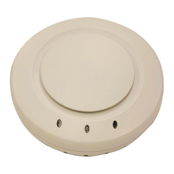
AP Model —Bottom View External antenna Kensington security connectors slot 802.11b/g 802.11a RJ-45 ports Port 2 Port 1 Cable Ports The access point has two RJ‐45 ports. (See Figure 1‐2.) Each port provides a 10/100BASE‐TX Ethernet connection to a switch. The AP receives power and data through the RJ‐45 ports. Use a Category 5 (Cat 5) cable with straight‐through signaling and standard RJ‐45 connectors to connect an AP to a RoamAbout Access Point or other device in the network. The RBT‐1602 and the RBT‐1602C supports 802.3af, and can receive PoE (Power over Ethernet) from Enterasys switches and Enterasys‐approved power injectors. (See the Release Notes.) The two RJ‐45 ports support dual‐homed configurations for redundancy. An access point uses only one link for booting, configuration, and data transfer. If the link becomes unavailable, the access point can reboot using the other link. The ports are identical except for logical numbering (1 or 2). You can use either port to connect an access point to a switch. 1-2 Access Point Overview... -
Page 17: Kensington Security Slot
External Hardware Features However, an AP always attempts to boot on AP port 1 first. Only if the boot attempt on port 1 fails does the AP attempt to boot on port 2. If one port becomes unavailable, the other port can provide full power to the AP. Note: APs do not support daisy-chain configurations. Do not connect one AP to another AP. Kensington Security Slot The access point has a slot for attachment of a Kensington security cable. The cable is not included with the AP, but can be ordered separately. Access Point Mounting Options You can mount the access point on any of the following types of surfaces: • Suspended T‐bar ceiling • Junction box • Solid surface wall or ceiling • Tabletop Note: The solid surface mounting option requires Cat 5 cable that does not have strain relief. The other mounting options can use Cat 5 cable with or without strain relief. -
Page 18: Connection Options
Connection Options Table 1-1 Access Point LEDs Appearance Meaning Health Solid green All the following are true: • Management link with a switch is operational. • AP has booted. • AP has received a valid configuration from a switch. • At least one radio is enabled or is in sentry mode. Solid amber AP is waiting to receive boot instructions and a configuration file from a switch. -
Page 19: Chapter 2: Installing And Connecting The Access Point
Installing and Connecting the Access Point For information about... Refer to page... Unpacking the Access Point Installation Requirements and Recommendations Installing the Access Point Connecting an Access Point to the Network 2-25 Verifying AP Health 2-26 Note: Before installing the RoamAbout Access Point, you might need to generate a network plan and an AP work order with RASM. -
Page 20: Installation Requirements And Recommendations
Shipping Carton Contents Mounting template Mobility point Universal Rubber feet mounting bracket T-bar clamps Mounting hardware Before you begin installation: Open the carton and carefully remove the contents, if you have not already done so. Place the packing materials back in the carton, and save the carton. Verify that you received each item in the previous list. If any item is missing or damaged, contact Enterasys Networks. Installation Requirements and Recommendations For best results, follow these requirements and recommendations before installing a RoamAbout Access Point. RASM Network Plan and Work Orders If you are using RASM to plan your Enterasys Networks Mobility System installation, you might want to create and verify a network plan for the entire Enterasys network installation and generate an AP work order, before installing APs. A network plan and the AP work orders generated from it provide the following information about AP installation and configuration: • Number of APs required for adequate WLAN capacity in each coverage area •... -
Page 21: Switch Recommendation
Advertencia: el RoamAbout Access Point modelo RBT -1602, RBT-1602C, está diseñado para usarse sólo con una fuente de alimentación compatible con 802.3af, un switch de Enterasys Networks o fuentes de alimentación tipo "power injector" aprobadas por Enterasys. Achtung: RoamAbout Access Point (Modell RBT-1602, RBT-1602C) kann Strom ausschließlich über eine 802.3af-konforme Quelle, einen Enterasys Networks-Switch oder einen von Enterasys... -
Page 22: Cable Requirements
Note: The access point is intended for indoor use only. Do not install the device outdoors, unless you install it in a properly installed Enterasys Networks outdoor AP enclosure. Note: To reduce the possibility of connection interference caused by dust, clean the Cat 5 connector pins before inserting a cable into an AP. -
Page 23: Installing The Access Point
Installing the Access Point Installing the Access Point To install the access point, use one of the following procedures in this section: • Suspended Ceiling Installation—Flush Ceiling Tiles • Suspended Ceiling Installation—Drop Ceiling Tiles Installation Hardware and Tools Table 2‐2 lists the mounting hardware and tools required for each type of installation. Table 2-2 Required Mounting Hardware and Tools Included with the Mounting Option Required Hardware and Tools Product Suspended ceiling—flush Mounting template ceiling tiles Universal mounting bracket T-bar clamp... -
Page 24: Suspended Ceiling Installation-Flush Ceiling Tiles
Installing the Access Point Note: The RBT-1602 and RBT-1602C UL2043 plenum rated, so it also can be installed in the space above the ceiling if preferred. Figure 2‐2 shows the universal mounting bracket. Figure 2-2 Universal Mounting Bracket Port connector opening Screw holes T-bar flanges Suspended Ceiling Installation—Flush Ceiling Tiles (For required mounting hardware and tools, see Table 2‐2 on page 2‐5.) -
Page 25: Step 4—Installing A T-Bar Clamp
Installing the Access Point Install the 14.2‐mm (9/16‐inch) T‐bar clamp onto the ceiling T‐bar as shown in Figure 2‐3. Slide each half of the clamp onto the T‐bar so that the clamp lip is fully on the T‐bar. b. Slide the two halves of the clamp toward each other until the tabs are inserted completely into the holes and the clamp fits snugly on the T‐bar. Figure 2-3 Step 4—Installing a T-bar Clamp T-bar Slide together T-bar clamp halves Unlock the universal mounting bracket from the access point by inserting the 3‐mm or 1/8‐inch screwdriver into the Unlock hole on the access point as shown in Figure 2‐4. Caution: To avoid damage to the access point’s lock mechanism or electronic components, do not use excessive force when inserting a tool into the Unlock or Lock hole. -
Page 26: Step 6—Removing The Bracket
Installing the Access Point Remove the bracket as shown in Figure 2‐5. Figure 2-5 Step 6—Removing the Bracket Install the universal mounting bracket as follows onto the T‐bar or T‐bar clamp: As shown in Figure 2‐6, place the universal mounting bracket against the T‐bar or clamp so that the two screw holes face downward and the two T‐bar flanges face upward and are adjacent to the T‐bar edges. Figure 2-6 Step 7—Top View Universal mounting bracket T-bar Port connector opening (Viewed from above ceiling tiles, looking down.) b. Properly align the bracket for mounting by placing the bracket so that its port connector opening is to the left of the hole you cut for the cables. Rotate the universal mounting bracket clockwise until the flanges snap into place on the T‐bar or clamp as shown in Figure 2‐7. -
Page 27: Step 7—Bottom View
Installing the Access Point Figure 2-7 Step 7—Bottom View Port connector Universal mounting bracket opening T-bar Pull the Cat 5 cable(s) about 15 cm (about 6 inches) out of the hole in the ceiling tile and through the port connector opening to create enough slack to insert the cable(s). Insert the Cat 5 cable(s) into the connector(s): – For a single connection, use the connector for port 1. – For redundancy, insert one cable into each connector. 10. Install the Kensington lock, if you plan to use one. Loop the Kensington lock’s cable around an object that cannot be moved or damaged by a person pulling on the cable. b. Insert the key into the Kensington lock. Insert the Kensington lock into the security slot on the AP. d. Rotate the key right or left to secure the lock to the AP. Pull on the lock to verify that it is secured to the AP. Remove the key. Lift the access point into place on the universal mounting bracket as shown in Figure 2‐8. Make sure the cable feeds properly into the ceiling as you lift the device, and does not become ... -
Page 28: Suspended Ceiling Installation-Drop Ceiling Tiles
Installing the Access Point 12. Lock the access point onto the bracket by inserting the 3‐mm or 1/8‐inch screwdriver into the Lock hole on the access point as shown in Figure 2‐9. Caution: To prevent possible damage to the access point, make sure the device is fully locked onto the bracket before letting go of it. Advertencia: para evitar posibles daños al punto de acceso, asegúrese de que el dispositivo esté... -
Page 29: Step 3-Installing The T-Bar Clamp For A 23.9-Mm (15/16-Inch) T-Bar
Installing the Access Point Install the T‐bar clamp that fits the T‐bar: Slide each half of the clamp onto the T‐bar so that the clamp lip is fully on the T‐bar. b. Slide the two halves of the clamp toward each other until the tabs are inserted completely into the holes and the clamp fits snugly on the T‐bar. Figure 2‐10 shows an example for a 23.9‐mm (15/16‐inch) T‐bar. Figure 2‐11 shows an example for a 15.9‐mm (5/8‐inch) T‐bar. Figure 2-10 Step 3—Installing the T-bar Clamp for a 23.9-mm (15/16-inch) T-bar T-bar Slide together T-bar clamp halves Figure 2-11 Step 3—Installing the T-bar Clamp for a 15.9-mm (5/8-inch) T-bar T-bar Slide together T-bar clamp halves... -
Page 30: Step 4—Unlocking The Bracket
Installing the Access Point Unlock the universal mounting bracket from the access point by inserting the 3‐mm or 1/ 8‐inch screwdriver into the Unlock hole on the access point as shown in Figure 2‐12. Caution: To avoid damage to the access point’s lock mechanism or electronic components, do not use excessive force when inserting a tool into the Unlock or Lock hole. Advertencia: para evitar daños en el mecanismo de cierre del punto de acceso o en los componentes electrónicos, no introduzca con fuerza ninguna herramienta en el agujero de "Unlock y Lock"... -
Page 31: Step 6—Top View
Installing the Access Point Install the universal mounting bracket as follows onto the T‐bar clamp: As shown in Figure 2‐14, place the universal mounting bracket against the T‐bar clamp so that the two screw holes face downward and the two T‐bar flanges face upward and are adjacent to the T‐bar edges. b. Properly align the bracket for mounting by placing the bracket so that its port connector opening is to the left of the hole you cut for the cables. Rotate the universal mounting bracket clockwise until the flanges snap into place on the T‐bar clamp as shown in Figure 2‐15. Figure 2-14 Step 6—Top View Universal mounting bracket T- bar T-bar clamps (attached to T-bar) Port connector opening (Viewed from above ceiling tiles, looking down.) Figure 2-15 Step 6—Bottom View Port connector... -
Page 32: Step 9—Placing The Access Point On The Bracket
Installing the Access Point Install the Kensington lock, if you plan to used one. Loop the Kensington lock’s cable around an object that cannot be moved or damaged by a person pulling on the cable. b. Insert the key into the Kensington lock. Insert the Kensington lock into the security slot on the AP. d. Rotate the key right or left to secure the lock to the AP. Pull on the lock to verify that it is secured to the AP. Remove the key. Lift the access point into place on the universal mounting bracket as shown in Figure 2‐16. Make sure the cable feeds properly into the ceiling as you lift the device, and does not become trapped between the access point and the bracket. Figure 2-16 Step 9—Placing the Access Point on the Bracket 2-14 Installing and Connecting the Access Point... -
Page 33: Step 10-Locking The Bracket
Installing the Access Point 11. Lock the access point onto the bracket by inserting the 3‐mm or 1/8‐inch screwdriver into the Lock hole on the access point as shown in Figure 2‐17. Caution: To prevent possible damage to the access point, make sure the device is fully locked onto the bracket before letting go of it. Advertencia: para evitar posibles daños al punto de acceso, asegúrese de que el dispositivo esté... -
Page 34: Junction Box Installation
Installing the Access Point Junction Box Installation (For required mounting hardware and tools, see “Required Mounting Hardware and Tools” on page 2‐5.) Unlock the universal mounting bracket from the access point by inserting the 3‐mm or 1/8‐inch screwdriver into the Unlock hole on the access point as shown in Figure 2‐18. Caution: To avoid damage to the access point’s lock mechanism or electronic components, do not use excessive force when inserting a tool into the Unlock or Lock hole. Advertencia: para evitar daños en el mecanismo de cierre del punto de acceso o en los componentes electrónicos, no introduzca con fuerza ninguna herramienta en el agujero de "Unlock y Lock"... -
Page 35: Step 3—Placing The Bracket On The Junction Box
Installing the Access Point Attach the universal mounting bracket to the junction box as shown in Figure 2‐20: Place the universal mounting bracket against the junction box so that the two screw holes face the junction box and align over the screw holes in the box. b. Insert the #6‐32 x 1‐inch machine screws in the universal mounting bracket’s screw holes, and use a #2 Phillips‐head screwdriver to tighten them. Figure 2-20 Step 3—Placing the Bracket on the Junction Box Junction box Port connector opening Pull the Cat 5 cable(s) about 15 cm (about 6 inches) out of the junction box and through the port connector opening to create enough slack to insert the cable(s) into the port connectors. Insert the Cat 5 cable(s) into the connector(s): – For a single connection, use the connector for port 1. – For redundancy, insert one cable into each connector. Install the Kensington lock, if you plan to use one. Loop the Kensington lock’s cable around an object that cannot be moved or damaged by a person pulling on the cable. -
Page 36: Solid Wall Or Ceiling Installation
Installing the Access Point Lock the access point onto the bracket by inserting the 3‐mm or 1/8‐inch screwdriver into the Lock hole on the access point as shown in Figure 2‐21. Caution: To prevent possible damage to the access point, make sure the device is fully locked onto the bracket before letting go of it. Advertencia: para evitar posibles daños al punto de acceso, asegúrese de que el dispositivo esté... -
Page 37: Step 3—Unlocking The Bracket
Installing the Access Point ‐ If you plan to route the Cat 5 cable through a hole in the wall or ceiling, mark the location of the center screw hole only. You cannot use the screw hole by the port connector opening if you cut a hole for the opening. Note: Do not mark the four holes on the edges of the bracket. (These are the holes indicated by the dashed lines in Figure 2-24.) The access point fits into these holes. They are not screw holes. -
Page 38: Steps 5 And 6-Bracket Placement On Solid Wall Or Ceiling
Installing the Access Point Figure 2-23 Step 4—Removing the Bracket As shown in Figure 2‐24, feed the Cat 5 cable(s) through the port connector opening and align the universal mounting bracket over the drywall anchors so that the two screw holes in the bracket face the drywall anchors. Insert the #6 sheet metal screws into the screw holes, and tighten them to secure the universal mounting bracket to the wall or ceiling. (If you routed the Cat 5 cable through a hole in the wall or ceiling, insert the screw into the center screw hole only.) Note: Do not insert screws in the four holes on the edges of the bracket. (These are the holes indicated by the dashed lines in Figure 2-24.) The access point fits into these holes. -
Page 39: Step 8—Cable Placement
Installing the Access Point Install the Kensington lock, if you plan to use one. Loop the Kensington lock’s cable around an object that cannot be moved or damaged by a person pulling on the cable. b. Insert the key into the Kensington lock. Insert the Kensington lock into the security slot on the AP. d. Rotate the key right or left to secure the lock to the AP. Pull on the lock to verify that it is secured to the AP. Remove the key. As shown in Figure 2‐25, place the access point on the bracket, making sure to remove any slack that occurs in the cable between the bracket and the access point. Figure 2-25 Step 8—Cable Placement Cable Universal mounting bracket 10. Lock the access point onto the bracket by inserting the 3‐mm or 1/8‐inch screwdriver into the Lock hole on the access point as shown in Figure 2‐26. Caution: To prevent possible damage to the access point, make sure the device is fully locked onto the bracket before letting go of it. -
Page 40: Tabletop Installation
Installing the Access Point Figure 2-26 Step 9—Locking the Bracket Lock 11. To ensure that the access point is fully locked onto the bracket, gently pull on the access point and attempt to rotate it from side to side. If the access point comes off the bracket, relock the device onto the bracket as described in Step 10 on page 2‐21. 12. If the other ends of the Cat 5 cable(s) are not already connected and the link activated, go to “Connecting an Access Point to the Network” on page 2‐25. Otherwise, go to “Verifying AP Health” on page 2‐26. Tabletop Installation (For required mounting hardware and tools, see Table 2‐2 on page 2‐5.) Reverse the universal mounting bracket: Unlock the universal mounting bracket from the access point by inserting the 3‐mm or 1/8‐inch screwdriver into the Unlock hole on the access point as shown in Figure 2‐27. Caution: To avoid damage to the access point’s lock mechanism or electronic components, do not use excessive force when inserting a tool into the Unlock or Lock hole. -
Page 41: Step 1A-Unlocking The Bracket
Installing the Access Point Figure 2-27 Step 1a—Unlocking the Bracket Remove the bracket as shown in Figure 2‐28. Figure 2-28 Step 1b—Removing the Bracket b. Turn over the universal mounting bracket, then align the bracket over the cable ports and the four mounting posts as shown in Figure 2‐29. Figure 2-29 Step 1c—Turning Over the Bracket Once the bracket is fully seated, lock the bracket onto the access point by inserting the 3‐mm or 1/8‐inch screwdriver into the Lock hole on the access point as shown in Figure 2‐30. RBT-1602 and RBT-1602C Wireless Access Point Installation Guide 2-23... -
Page 42: Step 1D-Locking The Bracket
Installing the Access Point Figure 2-30 Step 1d—Locking the Bracket Lock Attach the three rubber adhesive feet onto the universal mounting bracket, in the three location circles, as shown in Figure 2‐31. Figure 2-31 Step 2—Installing the Rubber Feet 2-24 Installing and Connecting the Access Point... -
Page 43: Connecting An Access Point To The Network
Connecting an Access Point to the Network Insert the Cat 5 cable(s) into the connector(s): – For a single connection, use the connector for port 1. – For redundancy, insert one cable into each connector. Install the Kensington lock, if you plan to use one. Loop the Kensington lock’s cable around an object that cannot be moved or damaged by a person pulling on the cable. b. Insert the key into the Kensington lock. Insert the Kensington lock into the security slot on the AP. d. Rotate the key right or left to secure the lock to the AP. Pull on the lock to verify that it is secured to the AP. Remove the key. Place the access point in the desired location on the table. If the other ends of the Cat 5 cable(s) are not already connected and the link activated, go to “Connecting an Access Point to the Network” on page 2‐25. Otherwise, go to “Verifying AP Health” on page 2‐26. Connecting an Access Point to the Network You can connect an access point to the network via a switch that provides PoE, or to the network with a PoE power injector. Insert the Cat 5 cable with a standard RJ‐45 connector. For connection to an access point, use a straight‐through cable. -
Page 44: Verifying Ap Health
Verifying AP Health Verifying AP Health After you install the access point and enable PoE on the Ethernet cable connected to the AP, you can easily verify the AP’s status by observing the LEDs, particularly the Health LED. (See Figure 2‐4 on page 2‐7.) The health or LINK LED indicates whether the access point is ready for operation. • If the LED is green and glowing steadily, the AP has been booted successfully by the switch and is ready for operation. • If the LED is not steadily glowing green, contact the system administrator for the switch or, if you are the system administrator, see Appendix A, Access Point Troubleshooting. 2-26 Installing and Connecting the Access Point... -
Page 45: Appendix A: Access Point Troubleshooting
For an indirect connection through the network: • Configure a Distributed AP connection on a switch. • Verify that an Enterasys-approved PoE source is supplying power to the AP. Slowly alternating AP is booting with an image... - Page 46 A-2 Access Point Troubleshooting...
-
Page 47: Appendix B: Technical Specifications
Table B‐3, and Table B‐4 list the radio specifications. Table B‐5 lists the MAC address allocation scheme. Note: This Listed Accessory is designed and approved to be used only with Enterasys Networks RoamAbout switch models. The RBT-8110, RBT-8210, and the RBT-8400 wireless switches do not directly connect to the AP. Note: The AP radios are disabled by default and can be enabled only by the system administrator using the RASM management application or the switch’s command-line interface (CLI). -
Page 48: B-2 802.11A Radio Specifications
Table B-1 AP Mechanical and Compliance Specifications (continued) Specification Description Standards compliance IEEE 802.11 IEEE 802.11a IEEE 802.11b IEEE 802.11g IEEE 802.3af Safety and electromagnetic FCC Part 15, UL 60950 compliance UL 2043 Plenum Rated IC Part 15, CSA 22.2 N0-950, RSS-139-1 and RSS-210 ETS 300 328 (2.4 GHz) and 301 893 (5 GHz), EN 301 489-17 R&TTE Directive 1999/5/EC TELEC, ARIB T66... -
Page 49: B-3 802.11B Radio Specifications
Table B-2 802.11a Radio Specifications (continued) Specification Description Receiver Sensitivity -70 dBm @ 54 Mbps -73 dBm @ 48 Mbps -76 dBm @ 36 Mbps -82 dBm @ 24 Mbps -84 dBm @ 18 Mbps -86 dBm @ 12 Mbps -90 dBm @ 9 Mbps -91 dBm @ 6 Mbps... -
Page 50: Mac Address Allocations On The Access Point
Table B-4 802.11g Radio Specifications (continued) Specification Description Receiver Sensitivity -71 dBm @ 54 Mbps -73 dBm @ 48 Mbps -78 dBm @ 36 Mbps -81 dBm @ 24 Mbps -85 dBm @ 18 Mbps -87 dBm @ 12 Mbps -89 dBm @ 9 Mbps -90 dBm @ 6 Mbps... -
Page 51: Appendix C: Translated Warning Conventions And Warnings
Translated Warning Conventions and Warnings The following warnings apply to this document. Warning Conventions Warning: This situation or condition can cause injury. Waarschuwing! Deze situatie of omstandigheid kan letsel veroorzaken. Warnung! Diese Situation oder dieser Zustand kann zu Verletzungen führen. Avertissement ! Cette situation ou cette condition peuvent provoquer des blessures. Aviso Esta situación o condición puede causar lesiones. -
Page 52: Qualified Service Personnel Warning
Warnung! Die Installation darf nur von einem qualifizierten Kundendienstmitarbeiter vorgenommen werden. Lesen Sie alle Warnhinweise und Anweisungen auf dem Produkt oder in der Dokumentation und befolgen Sie sie. Bevor Sie das Produkt installieren, sollten Sie Enterasys Regulatory Information vollständig lesen. -
Page 53: Lightning Warning
Lightning Warning Warning: Do not hold any radio device so that the antenna is very close to or touching the face, eyes, or other exposed body part while the device's radio antenna is transmitting. Waarschuwing! De antenne van een apparaat dat radiogolven aan het uitzenden is, mag nooit vlakbij of tegen het gezicht, de ogen of een andere onbedekt deel van het lichaam worden gehouden. - Page 54 Lightning Warning C-4 Translated Warning Conventions and Warnings...
-
Page 55: Index
LED pin signals AP (access point) troubleshooting with specifications description of 1-1, verifying AP health 2-26 use with Enterasys devices only ports bracket installation access point radio LEDs junction box 2-16 radios cable ports requirements... - Page 56 tabletop installation 2-22 T-bar ceilings. See suspended ceilings technical specifications tools translated warnings troubleshooting universal mounting bracket unpacking wall installation junction box 2-16 recommendations solid 2-18 warnings cable installation radio translations work order, RASM Index-2...