
Related Manuals for Enterasys RoamAbout RBT-1002


Summary of Contents for Enterasys RoamAbout RBT-1002
-
Page 1: Wireless Access Point
RoamAbout RBT-1002 2.4 GHz / 5 GHz Wireless Access Point Installation Guide P/N 9034169-01... - Page 3 ENTERASYS NETWORKS reserves the right to make changes in specifications and other information contained in this document and its web site without prior notice. The reader should in all cases consult ENTERASYS NETWORKS to determine whether any such changes have been made.
- Page 4 This document is an agreement (“Agreement”) between the end user (“You”) and Enterasys Networks, Inc. on behalf of itself and its Affiliates (as hereinafter defined) (“Enterasys”) that sets forth Your rights and obligations with respect to the Enterasys software program/firmware installed on the Enterasys product (including any accompanying documentation, hardware or media) (“Program”) in the package and prevails over any additional, conflicting or inconsistent...
- Page 5 52.227-19 (a) through (d) of the Commercial Computer Software-Restricted Rights Clause and its successors, and (iii) in all respects is proprietary data belonging to Enterasys and/or its suppliers. For Department of Defense units, the Program is considered commercial computer software in accordance with DFARS section 227.7202-3 and its successors, and use, duplication, or disclosure by the...
- Page 6 (i) license fees due and paid, and (ii) the use, copying and deployment of the Program. You also grant to Enterasys and its authorized representatives, upon reasonable notice, the right to audit and examine during Your normal...
- Page 7 Agreement shall be void and a breach of this Agreement. 12. WAIVER. A waiver by Enterasys of a breach of any of the terms and conditions of this Agreement must be in writing and will not be construed as a waiver of any subsequent breach of such term or condition.
- Page 8 Notice...
-
Page 9: Federal Communication Commission Interference Statement
OMPLIANCES Federal Communication Commission Interference Statement This equipment has been tested and found to comply with the limits for a Class B digital device, pursuant to Part 15 of the FCC Rules. These limits are designed to provide reasonable protection against harmful interference in a residential installation. - Page 10 OMPLIANCES High power radars are allocated as primary users (meaning they have priority) of the 5250-5350 MHz and 5725-5850 MHz bands. These radars could cause interference and /or damage to the access point when used in Canada. The term “IC:” before the radio certification number only signifies that Industry Canada technical specifications were met.
-
Page 11: Table Of Contents
ABLE OF ONTENTS Introduction ......1-1 Package Checklist ....... . . 1-2 Hardware Description . -
Page 12: Able Of Ontents
ABLE OF ONTENTS... -
Page 13: Introduction
Chapter 1 Introduction The RoamAbout RBT-1002 Wireless Access Point is an IEEE 802.11a/g access point that provides transparent, wireless high-speed data communications between a wired LAN and fixed, portable or mobile devices equipped with an 802.11a, 802.11b or 802.11g wireless adapter. -
Page 14: Package Checklist
Introduction Package Checklist The RoamAbout RBT-1002 Wireless Access Point package includes: • One RoamAbout 1002 Wireless Access Point • One AC power adapter and power cord • Four rubber feet • Four wall-mounting screws • Bezel • This Installation Guide Optional Wireless Access Point Equipment: •... -
Page 15: Hardware Description
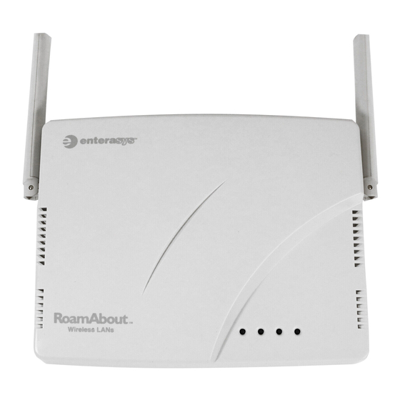
Hardware Description Hardware Description Top Panel Antennas Indicators Rear Panel Console Port Reset Button Bracket RJ-45 Port, Security Slot 5 VDC Power Fastening PoE Connector Socket Screw... -
Page 16: Component Description
Introduction Component Description Antennas The access point includes integrated diversity antennas for wireless communications. A diversity antenna system uses two identical antennas to receive and transmit signals, helping to avoid multipath fading effects. When receiving, the access point checks both antennas and selects the one with the strongest signal. - Page 17 Hardware Description Status Description Power Solid green Normal operation. All of the following are true: • Management link with a wireless switch is operational • Access point has booted • Access point has received a valid configuration from a wireless switch Slow blink Access point is booting and receiving green...
- Page 18 Introduction Status Description Solid green A client is associated with the radio, or the radio is in Sweep/Sentry mode. 11a and 11b/g Slow blink Radio is unable to transmit. This state (Wireless Link/ green can indicate inability to send a beacon Activity) (2 sec on/off) or radio failure.
- Page 19 Hardware Description However, when connecting the access point to a workstation or other device that does not have MDI-X ports, you must use crossover twisted-pair cable. The access point appears as an Ethernet node and performs a bridging function by moving packets from the wired LAN to remote workstations on the wireless infrastructure.
-
Page 20: Features And Benefits
Introduction Features and Benefits • Local network connection via 10/100 Mbps Ethernet ports or 54 Mbps wireless interface (supporting up to 127 mobile users) • IEEE 802.11a, 802.11b and 802.11g compliant • Interoperable with multiple vendors based on the IEEE 802.11f protocol •... -
Page 21: Hardware Installation
Chapter 2 Hardware Installation 1. Select a Site – Choose a proper place for the access point. In general, the best location is at the center of your wireless coverage area, within line of sight of all wireless devices. Try to place the access point in a position that can best cover its Basic Service Set. - Page 22 Hardware Installation Mounting on a wall – The access point should be mounted only to a wall or wood surface that is at least 1/2-inch plywood or its equivalent. To mount the access point on a wall, always use its wall-mounting bracket. a.
- Page 23 Hardware Installation lines up with the tab on the bracket. Then screw down the fastening screw to secure the access point to the bracket. Mounting Points Fastening Screw Align this tab with the Fastening Screw Mounting Slots Bracket...
- Page 24 Hardware Installation 3. Lock the Access Point in Place – To prevent unauthorized removal of the access point, you can use a Kensington Slim MicroSaver security cable (not included) to attach the access point to a fixed object. 4. Connect the Ethernet Cable – The access point can be wired to a 10/100 Mbps Ethernet network through a device such as a hub or a switch.
- Page 25 Hardware Installation 6. Observe the Self Test – When you power on the access point, verify that the Power indicator stops blinking and remains on green, and that the other indicators start functioning as described under “LED Indicators” on page 1-4. If the Power LED does not stop blinking or turns on yellow, the self test has not completed correctly.
- Page 26 Hardware Installation Bezel Fastening Slot To remove the bezel, grasp both sides and gently pry away from the fastening slots located on each antenna side. Pull the bezel clear of the access point.
-
Page 27: Configuration
Chapter 3 Configuration All configuration of the RBT-1002 is done from the RoamAbout wireless switch and the RoamAbout Switch Manager interface. Refer to the RoamAbout Switch Manager User Guide and the RoamAbout Mobility System Software Configuration Guide for configuration information. - Page 28 Configuration...
-
Page 29: Troubleshooting
Appendix A Troubleshooting For troubleshooting information, refer to the RoamAbout Mobility System Software Configuration Guide. - Page 30 Troubleshooting...
-
Page 31: Cables And Pinouts
Appendix B Cables and Pinouts Twisted-Pair Cable Assignments For 10/100BASE-TX connections, a twisted-pair cable must have two pairs of wires. Each wire pair is identified by two different colors. For example, one wire might be green and the other, green with white stripes. Also, an RJ-45 connector must be attached to both ends of the cable. -
Page 32: 10/100Base-Tx Pin Assignments
Cables and Pinouts 10/100BASE-TX Pin Assignments Use unshielded twisted-pair (UTP) or shielded twisted-pair (STP) cable for RJ-45 connections: 100-ohm Category 3 or better cable for 10 Mbps connections, or 100-ohm Category 5 or better cable for 100 Mbps connections. Also be sure that the length of any twisted-pair connection does not exceed 100 meters (328 feet). -
Page 33: Straight-Through Wiring
Twisted-Pair Cable Assignments Straight-Through Wiring Because the 10/100 Mbps port on the access point uses an MDI pin configuration, you must use “straight-through” cable for network connections to hubs or switches that only have MDI-X ports. However, if the device to which you are connecting supports auto-MDIX operation, you can use either “straight-through”... - Page 34 Cables and Pinouts...
-
Page 35: Specifications
Appendix C Specifications General Specifications Maximum Channels 802.11a: US & Canada: 12 802.11b/g: FCC/IC: 1-11 Maximum Clients 127 total clients for the AP Operating Range Refer to the RoamAbout Switch Manager User Guide Data Rate 802.11a: 6, 9, 12, 18, 24, 36, 48, 54 Mbps per channel 802.11g: 6, 9, 11, 12, 18, 24, 36, 48, 54 Mbps per channel 802.11b: 1, 2, 5.5, 11 Mbps per channel Modulation Type... - Page 36 Specifications Operating Frequency 802.11a: 5.150 ~ 5.250 GHz (lower band) US/Canada 5.250 ~ 5.350 GHz (middle band) US/Canada 5.725 ~ 5.850 GHz (upper band) US/Canada 802.11b: 2.4 ~ 2.4835 GHz (US, Canada) AC Power Adapters Input: 100-240 AC, 50-60 Hz Output: 5 VDC, 3 A or 2 A Maximum Power: 13.2 W Unit Power Supply...
-
Page 37: General Specifications
General Specifications Humidity 15% to 95% (non-condensing) Compliances FCC Class B (US) ICES-003 (Canada) Radio Signal Certification FCC Part 15.247 (2.4 GHz) FCC part 15 15.407(b) RSS-210 (Canada) Safety CSA/NTRL (CSA 22.2 No. 950 & UL 60950) Ü EN60950 (T V/GS), IEC60950 (CB) Standards IEEE 802.3 10BASE-T, IEEE 802.3u 100BASE-TX,... -
Page 38: Sensitivity
Specifications Sensitivity IEEE 802.11a Sensitivity (GHz - dBm) Modulation/Rates 5.150-5.250 5.250-5.350 5.725-5.850 BPSK (6 Mbps) BPSK (9 Mbps) QPSK (12 Mbps) QPSK (18 Mbps) 16 QAM (24 Mbps) 16 QAM (36 Mbps) 64 QAM (48 Mbps) 64QAM(54 Mbps) IEEE 802.11g Data Rate Sensitivity (dBm) 6 Mbps... -
Page 39: Transmit Power
General Specifications Transmit Power(EIRP) IEEE 802.11a Maximum Output Power (GHz - dBm) Data Rate 5.15-5.250 5.25-5.350 5.725-5.850 6 Mbps 9 Mbps 12 Mbps 8 Mbps 24 Mbps 36 Mbps 48 Mbps 54 Mbps IEEE 802.11g Maximum Output Power (GHz - dBm) Data Rate 2.412 2.417~2.462... - Page 40 Specifications...
-
Page 41: Index
Index antenna description 1-4 IEEE 802.11a 1-1 antennas, positioning 2-5 installation hardware 2-1 mounting 2-1 bezel 1-2 attaching and removing the bezel 2-5 LED indicators 1-4 lock, Kensington 2-2 cable assignments B-1 MDI, RJ-45 pin configuration 1-6 crossover B-3 mounting bracket 2-3 straight-through B-3 mounting the access point 2-1 channels, maximum C-1... - Page 42 Index straight-through cable B-3 system defaults 1-8 security slot 1-6 self test 2-5 site selection 2-1 specifications C-1 troubleshooting A-1 Index-2...
- Page 44 Model Number: RBT-1002 Pub. Number: 150200025200E, E092005-R01...