Table of Contents
Advertisement
Quick Links
Advertisement
Table of Contents

Related Manuals for Jeep RENEGADE 2017


Summary of Contents for Jeep RENEGADE 2017
- Page 1 Renegade 2 0 1 7 O W N E R ’ S M A N U A L...
- Page 2 This manual illustrates and describes the operation of VEHICLES SOLD IN CANADA With respect to any Vehicles Sold in Canada, the name FCA features and equipment that are either standard or op- US LLC shall be deemed to be deleted and the name FCA tional on this vehicle.
- Page 3 TABLE OF CONTENTS SECTION PAGE INTRODUCTION ..............3 GRAPHICAL TABLE OF CONTENTS .
- Page 5 INTRODUCTION CONTENTS ▫ Symbols .......6 INTRODUCTION ......4 ROLLOVER WARNING .
-
Page 6: Introduction 3
When it comes to service, remember that your authorized and transfer case shifting. Learn how your vehicle handles dealer knows your Jeep® vehicle best, has factory-trained on different road surfaces. Your driving skills will improve technicians and genuine MOPAR® parts, and cares about with experience. -
Page 7: Introduction
INTRODUCTION higher center of gravity, if this vehicle is out of control it Failure to use the driver and passenger seat belts provided may roll over while some other vehicles may not. is a major cause of severe or fatal injury. In fact, the U.S. government notes that the universal use of existing seat Do not attempt sharp turns, abrupt maneuvers, or other belts could cut the highway death toll by 10,000 or more... -
Page 8: Symbols
6 INTRODUCTION Symbols Consult the following table for a description of the symbols that may be used on your vehicle or throughout this Owner’s Manual:... -
Page 9: Warnings And Cautions
INTRODUCTION WARNINGS AND CAUTIONS VEHICLE MODIFICATIONS/ALTERATIONS This Owner’s Manual contains WARNINGS against oper- WARNING! ating procedures that could result in a collision, bodily injury and/or death. It also contains CAUTIONS against Any modifications or alterations to this vehicle could procedures that could result in damage to your vehicle. If seriously affect its roadworthiness and safety and may you do not read this entire Owner’s Manual, you may miss lead to a collision resulting in serious injury or death. - Page 11 GRAPHICAL TABLE OF CONTENTS CONTENTS FRONT VIEW ......10 INSTRUMENT PANEL .....12 REAR VIEW.
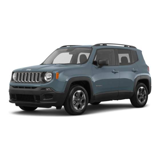
- Page 12 10 GRAPHICAL TABLE OF CONTENTS FRONT VIEW Front View 1 — Headlights 4 — Doors 2 — Engine Compartment 5 — Exterior Mirrors 3 — Windshield 6 — Wheels...
- Page 13 GRAPHICAL TABLE OF CONTENTS 11 REAR VIEW Rear View 1 — Rear Lights 2 — Rear Windshield Wiper 3 — Liftgate...
- Page 14 12 GRAPHICAL TABLE OF CONTENTS INSTRUMENT PANEL Instrument Panel 1 — Air Vents 5 — Glove Compartment 2 — Instrument Cluster 6 — Steering Wheel 3 — Windshield Wiper Lever 7 — Multifunction Lever 4 — Hand Grip 8 — Headlight Switch...
- Page 15 GRAPHICAL TABLE OF CONTENTS 13 INTERIOR Interior Features 1 — Power Window Switches 5 — Selec-Terrain Mode Knob — If Equipped 2 — Uconnect Radio 6 — Transmission Gear Selector (Automatic/Manual options) 3 — Switch Panel 7 — Seats 4 — Climate Controls...
- Page 17 GETTING TO KNOW YOUR VEHICLE CONTENTS ▫ Remote Start Windshield Wiper De–Icer Activation KEYS ....... . .19 —...
-
Page 18: Headlights
16 GETTING TO KNOW YOUR VEHICLE ▫ Keyless Enter-N-Go — Passive Entry — If ▫ Auto Dimming Mirror — If Equipped ..49 Equipped ......32 ▫... -
Page 19: Windshield
GETTING TO KNOW YOUR VEHICLE 17 ▫ Courtesy Lights ......56 ▫ Auto-Up Feature With Auto-Reverse Protection — If Equipped . - Page 20 18 GETTING TO KNOW YOUR VEHICLE ▫ Cargo Area Features .....102 ▫ Ashtray — If Equipped....115 ▫...
-
Page 21: Doors
GETTING TO KNOW YOUR VEHICLE 19 KEYS Key Fobs Your vehicle uses a keyless ignition system. The ignition system consists of a key fob with Remote Keyless Entry (RKE) and a START/STOP push button ignition system. The Remote Keyless Entry system consists of a key fob and Keyless Enter-N-Go feature. - Page 22 20 GETTING TO KNOW YOUR VEHICLE The turn signal lights will flash to acknowledge the unlock signal. The illuminated entry system will be activated. 1st Push Of Key Fob Unlock Button This feature lets you program the system to unlock either the driver’s door or all doors on the first push of the unlock button on the key fob.
- Page 23 GETTING TO KNOW YOUR VEHICLE 21 Vehicles Equipped With Keyless Enter-N-Go — Passive Duplication of key fobs may be performed at an authorized Entry dealer. This procedure consists of programming a blank key fob to the vehicle electronics. A blank key fob is one If one or more doors are open, or the liftgate is open, the that has never been programmed.
- Page 24 22 GETTING TO KNOW YOUR VEHICLE IGNITION SWITCH Models With Keyless Enter-N-Go — Passive Entry This feature allows the driver to operate the ignition switch with the push of a button as long as the key fob is in the passenger compartment.
- Page 25 GETTING TO KNOW YOUR VEHICLE 23 WARNING! (Continued) • Driving position. • Do not leave children or animals inside parked • All the electrical devices are available. vehicles in hot weather. Interior heat build-up may cause serious injury or death. NOTE: The vehicle will not start if the key fob is located inside the cargo area and the liftgate is opened.
- Page 26 24 GETTING TO KNOW YOUR VEHICLE NOTE: How To Use Remote Start • The vehicle must be equipped with an automatic trans- • Push Remote Start button on the key fob twice mission to be equipped with Remote Start. within five seconds. Pushing the Remote Start button a third time shuts the engine off.
- Page 27 GETTING TO KNOW YOUR VEHICLE 25 • PANIC button not pushed NOTE: • If an engine fault is present or fuel level is low, the • System not disabled from previous remote start event vehicle will start and then shut down in 10 seconds. •...
- Page 28 26 GETTING TO KNOW YOUR VEHICLE the door handles, and disarm the Vehicle Security Alarm (if previous operation, except if the Windshield Wiper De-Icer equipped). Then, prior to the end of the 15-minute cycle, is active. The Windshield Wiper De-Icer timer and opera- push and release the START/STOP button.
- Page 29 GETTING TO KNOW YOUR VEHICLE 27 The system uses a key fob, keyless push button ignition CAUTION! and a RF receiver to prevent unauthorized vehicle opera- tion. Therefore, only key fobs that are programmed to the The Sentry Key Immobilizer system is not compatible vehicle can be used to start and operate the vehicle.
- Page 30 28 GETTING TO KNOW YOUR VEHICLE NOTE: Changes or modifications not expressly approved CAUTION! (Continued) by the party responsible for compliance could void the • For vehicles equipped with Keyless Enter-N-Go — user’s authority to operate the equipment. Ignition, always remember to place the ignition in the OFF position.
- Page 31 GETTING TO KNOW YOUR VEHICLE 29 • Push the lock button on the interior power door lock NOTE: switch with the driver and/or passenger door open. • The driver’s door key cylinder and the liftgate button on • Push the lock button on the exterior Passive Entry the key fob cannot arm or disarm the vehicle security Door Handle with a valid key fob available in the same alarm.
- Page 32 30 GETTING TO KNOW YOUR VEHICLE remain armed when the battery is reconnected; the exterior Locking/Unlocking Doors From Outside lights will flash, and the horn will sound. If this occurs, With the doors closed, insert the key blade into the driver disarm the vehicle security alarm.
- Page 33 GETTING TO KNOW YOUR VEHICLE 31 Power Door Locks WARNING! A power door lock switch is located on each of the front • For personal security and safety in the event of a door trim panels. Use this switch to lock or unlock the collision, lock the vehicle doors before you drive as doors, liftgate and fuel door.
- Page 34 32 GETTING TO KNOW YOUR VEHICLE • If the vehicle is unlocked by the Passive Entry Door The doors can also be locked and unlocked with the Keyless Enter-N-Go — Passive Entry system if equipped. Handle, and no door is opened within 60 seconds, the refer to “Keyless Enter-N-Go —...
- Page 35 GETTING TO KNOW YOUR VEHICLE 33 NOTE: All doors will unlock when the front passenger door handle is grabbed regardless of the driver’s door unlock preference setting (“Unlock Driver Door 1st Press” or “Unlock All Doors 1st Press”). To Lock The Vehicle’s Doors And Liftgate With one of the vehicle’s Passive Entry key fobs within 5 ft (1.5 m) of the driver or passenger front door handles, push the door handle lock button to lock all four doors.
- Page 36 34 GETTING TO KNOW YOUR VEHICLE FOBIK-Safe only executes in vehicles with Passive Entry. There are three situations that trigger a FOBIK-Safe search in any Passive Entry vehicle: 1. A lock request is made by a valid Passive Entry key fob while a door is open.
- Page 37 GETTING TO KNOW YOUR VEHICLE 35 To Unlock/Enter The Liftgate The liftgate Passive Entry unlock feature is built into the electronic liftgate release. With a valid Passive Entry key fob within 5 ft (1.5 m) of the liftgate, push the Electronic Liftgate release to open with one fluid motion.
- Page 38 36 GETTING TO KNOW YOUR VEHICLE 2. Remove the emergency key from the key fob with WARNING! Remote Control housing. • Never leave children alone in a vehicle, or with access to an unlocked vehicle. Allowing children to be in a vehicle unattended is dangerous for a number of reasons.
- Page 39 GETTING TO KNOW YOUR VEHICLE 37 Arming The Dead Lock Device • The device works on all doors and requires two presses of the lock button on the key fob. • The arming of the device is indicated by three flashes of the direction indicators.
- Page 40 38 GETTING TO KNOW YOUR VEHICLE • For emergency exit with the system engaged, rotate the WARNING! (Continued) lock/unlock dial to the unlocked position, roll down the In a collision, people riding in these areas are more window, and open the door with the outside door likely to be seriously injured or killed.
- Page 41 GETTING TO KNOW YOUR VEHICLE 39 Height Adjustment WARNING! The driver’s seat height can be raised or lowered by using • Adjusting a seat while the vehicle is moving is a lever, located on the outboard side of the seat. Pull dangerous.
- Page 42 40 GETTING TO KNOW YOUR VEHICLE Use the switch to move the seat up/down, forward/ Adjusting The Seat Up Or Down rearward, tilt (if equipped) and to set the angle of the The height of the seats can be adjusted up or down. Pull seatback.
- Page 43 GETTING TO KNOW YOUR VEHICLE 41 NOTE: Power seat adjustments are only allowed when the WARNING! (Continued) ignition device is turned to ON, and for about 30 minutes • Seats should be adjusted before fastening the seat after it is turned to OFF. The seats can also be moved after belts and while the vehicle is parked.
- Page 44 42 GETTING TO KNOW YOUR VEHICLE NOTE: The engine must be running for the heated seats to Rear Seats operate. Split Rear Seats Auto Comfort Systems — If Equipped The split rear seat has the ability to fold flat which increases In vehicles equipped with Auto On Comfort, when turning the storage of the rear cargo area.
- Page 45 GETTING TO KNOW YOUR VEHICLE 43 WARNING! (Continued) riding in these areas are more likely to be seriously injured or killed. • Do not allow people to ride in any area of your vehicle that is not equipped with seats and seat belts. •...
- Page 46 44 GETTING TO KNOW YOUR VEHICLE Cargo Area Enlargement Folding both sides of the rear seat provides additional storage in the rear cargo area. Proceed as follows: 1. Fully lower the rear seat head restraints. 2. Move the safety belts to the outboard side of the seat. 3.
- Page 47 GETTING TO KNOW YOUR VEHICLE 45 Rear Seat Center Armrest — If Equipped The center part of the rear seat can also be used as rear armrest with cupholders. Rear Armrest WARNING! Be certain that the seatback is securely locked into position.
- Page 48 46 GETTING TO KNOW YOUR VEHICLE HEAD RESTRAINTS To raise the head restraint, pull upward on the head restraint. To lower the head restraint, push the adjustment Head restraints are designed to reduce the risk of injury by button, located at the base of the head restraint, and push restricting head movement in the event of a rear impact.
- Page 49 GETTING TO KNOW YOUR VEHICLE 47 To lower the head restraint, push the adjustment button, WARNING! located at the base of the head restraint, and push down- • All occupants, including the driver, should not oper- ward on the head restraint. ate a vehicle or sit in a vehicle’s seat until the head restraints are placed in their proper positions in order to minimize the risk of neck injury in the event...
- Page 50 48 GETTING TO KNOW YOUR VEHICLE STEERING WHEEL To lock the steering column in position, pull the tilt/ telescoping lever upward until fully engaged. Tilt/Telescoping Steering Column This feature allows you to tilt the steering column upward WARNING! or downward. It also allows you to lengthen or shorten the Do not adjust the steering column while driving.
- Page 51 GETTING TO KNOW YOUR VEHICLE 49 Auto Comfort Systems — If Equipped can be reduced by moving the lever under the mirror to the night position (toward the rear of the vehicle). The mirror In vehicles equipped with Auto On Comfort, when turning should be adjusted while the lever under the mirror is set on the vehicle the heated steering wheel will automatically in the day position (toward the windshield).
- Page 52 50 GETTING TO KNOW YOUR VEHICLE left of the button will illuminate to indicate when the To adjust the mirror, push the mirror adjustment switch in dimming feature is activated. The sensor to the right of the the four directions indicated by arrows. button does not illuminate.
-
Page 53: Exterior Mirrors
GETTING TO KNOW YOUR VEHICLE 51 Manual Adjustment Mirrors — If Equipped To adjust the exterior mirrors, push the corners of the mirrors till desired alignment is obtained. Folding Exterior Mirror Heated Mirrors — If Equipped These mirrors are heated to melt frost or ice. This Manual Adjustment Mirror feature can be activated whenever you turn on the Folding Mirror... - Page 54 52 GETTING TO KNOW YOUR VEHICLE EXTERIOR LIGHTS Turning on the headlights will illuminate the instrument cluster and the controls located on the instrument panel. Headlights Daytime Running Lights (DRL) — If Equipped The headlight switch is located on the left side of the instrument panel.
- Page 55 GETTING TO KNOW YOUR VEHICLE 53 Automatic Lighting — If Equipped Turn the headlight switch to the AUTO position. When the automatic headlights are enabled, the headlight time delay is active. After the ignition is placed in the OFF position, the headlights will automatically turn off after the time is set by Uconnect Settings.
- Page 56 54 GETTING TO KNOW YOUR VEHICLE Automatic High Beam Headlamp Control — If Parking Lights Equipped From the O (off) position, rotate the headlight switch to the The Automatic High Beam Headlamp Control system first detent (parking position) to turn on the parking lights. provides increased forward lighting at night by automat- The parking light indicator in the instrument cluster will ing high beam control through the use of a digital camera...
-
Page 57: Wheels
GETTING TO KNOW YOUR VEHICLE 55 Headlight Delay Disable Cornering Lights The feature is disabled by turning on the headlights, the The cornering lights are a feature to improve visibility at parking lights or by placing the ignition in the RUN night while turning the vehicle. - Page 58 56 GETTING TO KNOW YOUR VEHICLE INTERIOR LIGHTS Courtesy Lights Interior Lights Dimmer Switch Rotate the ambient dimmer control upward or downward to increase or decrease the brightness of the ambient light located in the overhead console, door handle lights, lower instrument panel lights, door map pocket lights, and cubby bin lights.
- Page 59 GETTING TO KNOW YOUR VEHICLE 57 Front Lights The courtesy lights are mounted between the sun visors above the rear view mirror. The light switches are used to turn the lights on or off. Courtesy Light Switches 1— Left Switch 2—...
-
Page 60: Rear Lights
58 GETTING TO KNOW YOUR VEHICLE To operate the courtesy lights, push either the driver or passenger light switch. NOTE: • Before exiting the vehicle, make sure that the interior lights are turned off. This will prevent the battery from discharging once the doors are closed. - Page 61 GETTING TO KNOW YOUR VEHICLE 59 Vehicles With Retractable Roof For vehicles equipped with a retractable roof, there are two interior lights located above the grab handles of the rear doors. Interior Light Locations The lights come on by opening any of the doors. Rear Interior Light Dome Light Timing The Dome Light will automatically illuminate when the...
- Page 62 60 GETTING TO KNOW YOUR VEHICLE Timing Entering The Vehicle Timing Exiting The Vehicle The dome lights illuminate in the following ways: The dome light will illuminate under the following condi- tions when the ignition is placed to the OFF position and •...
-
Page 63: Liftgate
GETTING TO KNOW YOUR VEHICLE 61 WIPERS AND WASHERS The windshield wiper/washer controls are located on the lever on the right side of the steering column. The front wipers are operated by rotating a switch, located on the end of the lever. Vanity Mirror 1 —... - Page 64 62 GETTING TO KNOW YOUR VEHICLE CAUTION! WARNING! Always remove any buildup of snow that prevents the Sudden loss of visibility through the windshield could windshield wiper blades from returning to the “park” lead to a collision. You might not see other vehicles or position.
- Page 65 GETTING TO KNOW YOUR VEHICLE 63 NOTE: If the end of the multifunction lever rotates from off sensitive, and wiper delay position two is the most sensi- to the first intermittent setting or from the first intermittent tive. Place the wiper switch in the off position when not setting to the second intermittent setting, the wipers will using the system.
- Page 66 64 GETTING TO KNOW YOUR VEHICLE • Use of Rain-X or products containing wax or silicone rear wiper in an intermittent position will cause the front may reduce Rain Sensing performance. and rear wipers to sync up. Turning the front wipers off will cause the rear wipers to also stop.
- Page 67 GETTING TO KNOW YOUR VEHICLE 65 manually shut the defroster off, push the button a second cold weather manual start with full front defrost, and time. the ambient temperature is below 40° F (4.4° C). • Activation By Rear Defrost — The Windshield Wiper CAUTION! De-Icer will be activated automatically when the rear defrost is turned on and the ambient temperature is...
- Page 68 66 GETTING TO KNOW YOUR VEHICLE CLIMATE CONTROLS Air Outlet And Diffuser Locations — Passenger Compartment Center Air Outlets 1 — Fixed Air Outlet 2 — Air Flow Outlet Adjustment 3 — Air Vane Adjustment 4 — Adjustable Air Outlet Left Side Air Outlets 1 —...
- Page 69 GETTING TO KNOW YOUR VEHICLE 67 Manual Climate Controls Overview Right Side Air Outlets 1 — Fixed Air Outlet Manual Climate Controls 2 — Adjustable Air Outlet 3 — Air Vane Adjustment 4 — Air Flow Outlet Adjustment...
- Page 70 68 GETTING TO KNOW YOUR VEHICLE Manual Climate Control Descriptions Icon Description MAX A/C Setting MAX A/C sets the system for maximum cooling performance. Rotate the temperature control adjust knob counterclockwise to the MAX A/C setting. In MAX A/C, the blower speed and mode position can be adjusted to desired user settings.
- Page 71 GETTING TO KNOW YOUR VEHICLE 69 Icon Description Front Defrost Mode Air is directed through the windshield and side window demister outlets. Use this mode with maximum blower and temperature settings for best windshield and side window defrosting. NOTE: The air conditioning compressor operates in Mix or Defrost, even if the Air Condition- ing (A/C) button is not pushed.
- Page 72 70 GETTING TO KNOW YOUR VEHICLE Icon Description Panel Mode Panel Mode Air is directed through the outlets in the instrument panel. These outlets can be adjusted to di- rect airflow. The center instrument panel outlets can be adjusted so that they are directed to- ward the rear seat passengers for maximum airflow to the rear.
- Page 73 GETTING TO KNOW YOUR VEHICLE 71 CAUTION! CAUTION! Failure to follow these cautions can cause damage to To avoid causing damage to the rear window defroster the heating elements: heating filaments do not affix stickers or other objects • Use care when washing the inside of the rear win- to the inside of the rear glass.
- Page 74 72 GETTING TO KNOW YOUR VEHICLE System Maintenance Automatic Climate Control Overview In Winter, the Climate Control system must be turned on at least once a month for approximately 10 minutes. Have the system inspected at an authorized dealer before the summer.
- Page 75 GETTING TO KNOW YOUR VEHICLE 73 Icon Description A/C Button Push the A/C Control Button to change the current setting. The indicator illuminates when the A/C is ON. Pushing the AUTO control button will cause the A/C operation to change to AUTO mode and the A/C indicator will turn off.
- Page 76 74 GETTING TO KNOW YOUR VEHICLE Icon Description MAX Defrost Button Push the MAX Defrost button to change the current airflow setting to Defrost mode. The indica- tor illuminates when this feature is on. Performing this function will cause the automatic climate controls to change to manual mode.
- Page 77 GETTING TO KNOW YOUR VEHICLE 75 Icon Description Blower Control Knob Blower control is used to regulate the amount of air forced through the climate system. Adjust- ing the blower will cause the automatic mode to change to manual operation. The speeds can be selected by rotating the Blower Control adjustment knob.
- Page 78 76 GETTING TO KNOW YOUR VEHICLE Icon Description Bi-Level Mode Bi-Level Mode Bi-Level Mode is obtained by pressing both the Panel Mode button and the Floor Mode button, activating them both. Air comes from the instrument panel outlets and floor outlets. A slight amount of air is directed through the defrost and side window demister outlets.
- Page 79 GETTING TO KNOW YOUR VEHICLE 77 NOTE: With the compressor off, air cannot be introduced CAUTION! to the passenger compartment with a temperature lower than the outside temperature. Under certain environmental Failure to follow these cautions can cause damage to conditions, windows could fog rapidly since the air is not the heating elements: •...
- Page 80 78 GETTING TO KNOW YOUR VEHICLE • Turns air recirculation off. Rear Window Defrosting • Sets blower fan to the maximum speed. Push and release the rear window defrost button to turn the function on/off. • Directs air flow to windshield and front side window diffusers.
- Page 81 GETTING TO KNOW YOUR VEHICLE 79 NOTE: The Climate Control unit stores the temperatures Automatic Temperature Control (ATC) — If set before the system was turned off and restores them Equipped when one of the following knobs/buttons is pushed: Automatic Operation •...
- Page 82 80 GETTING TO KNOW YOUR VEHICLE NOTE: Operating Tips • It is not necessary to move the temperature settings. The NOTE: Refer to the chart at the end of this section for system automatically adjusts the temperature, mode, suggested control settings for various weather conditions. and fan speed to provide comfort as quickly as possible.
- Page 83 GETTING TO KNOW YOUR VEHICLE 81 Vacation/Storage Outside Air Intake Before you store your vehicle, or keep it out of service (i.e., Make sure the air intake, located directly in front of the vacation) for two weeks or more, run the air conditioning windshield, is free of obstructions such as leaves.
- Page 84 82 GETTING TO KNOW YOUR VEHICLE Operating Tips Chart...
- Page 85 GETTING TO KNOW YOUR VEHICLE 83 WINDOWS There are single window controls on each passenger door trim panel, which operate the passenger door windows. Power Window Controls The window controls will operate only when the ignition is The power window switch is located on the driver’s door in the ON or RUN position.
- Page 86 84 GETTING TO KNOW YOUR VEHICLE Auto-Down Feature NOTE: • If the window runs into any obstacle during auto- The driver door power window switch and the passenger closure, it will reverse direction and then go back down. door power window switches have an Auto-Down feature. Remove the obstacle and use the window switch again Push the window switch down, for a short period of time, to close the window.
- Page 87 GETTING TO KNOW YOUR VEHICLE 85 2. Push the window switch down firmly to open the MY SKY SUN ROOF — IF EQUIPPED window completely and continue to hold the switch Removable Roof — If Equipped down for an additional two seconds after the window is The roof consists of front and rear panels that can be fully open.
- Page 88 86 GETTING TO KNOW YOUR VEHICLE Power My Sky — If Equipped Open/Close The Front Panel The power My Sky switches are located on the overhead console. The switches are used to open and close the front panel. My Sky Retractable Roof Removed On some vehicles the front panel can be power operated.
- Page 89 GETTING TO KNOW YOUR VEHICLE 87 During the vent operation any push on the open/close switch will stop the closing of the panel. NOTE: If the My Sky is in open position, the vent switch must be held until the panel vents. Auto-Reverse Feature The front panel of the retractable roof is equipped with a auto-reverse safety system that is able to detect the pres-...
- Page 90 88 GETTING TO KNOW YOUR VEHICLE 2. Locate the My Sky Key inside the panel storage bag in 3. From inside of the passenger compartment, insert the the cargo area. My Sky Key into the latch key hole. My Sky Key Latch Key Hole...
- Page 91 GETTING TO KNOW YOUR VEHICLE 89 4. Rotate and keep the key turned to the symbol to release 5. Pull the panel handle down and away from the stowed the lock. position, unlocking the panel. Rotating My Sky Key Unlocking Panel Handle...
- Page 92 90 GETTING TO KNOW YOUR VEHICLE 6. Remove the key from the latch key hole. 7. Push panel up and away from latch to create a small gap. Removing Key Push Panel Up...
- Page 93 9. Place the panel inside of the provided bag for storage in the cargo area. Repeat the process for the rear panel. NOTE: An air deflector is available on the Jeep accessory Guide Tabs line. This deflector may be used to avoid the “wind buffeting”...
- Page 94 92 GETTING TO KNOW YOUR VEHICLE 4. From inside the vehicle, pull the handle down and toward the stowed position, locking it into place. Push To Lock Panel Closing Panel Handle 5. Make sure that the panel has been properly refitted. From inside the passenger compartment, push upward on the panel from the bottom, in order to verify that it is properly latched to the clamping locks.
- Page 95 GETTING TO KNOW YOUR VEHICLE 93 Bag For Housing Panels — If Equipped For proper housing, proceed as follows: After the panels have been removed, store the roof panels 1. Open the Roof Panel Bag and lift the panel dividers inside of the bag located inside the storage compartment.
- Page 96 94 GETTING TO KNOW YOUR VEHICLE 2. Place the front panel into the bag and fold the panel dividers down. Second Panel In Storage Bag 4. Close the bag and place it on the inside the cargo area. First Panel In Storage Bag 5.
- Page 97 GETTING TO KNOW YOUR VEHICLE 95 Tie-Down Straps NOTE: • Do not load objects that weigh over 165 pounds (75 kg) Tie-Down Hook Locations on top of the Roof Panel Bag. • The bag is washable. Refer to the documentation that is supplied with the bag.
- Page 98 96 GETTING TO KNOW YOUR VEHICLE 2. Remove the Allen Key or My Sky Key that is supplied in CAUTION! the tool bag in the cargo area. • When refitting panels, be careful to avoid fingers, 3. Insert the Allen Key or My Sky Key into the key hole scarves, ties and items of clothing from getting and turn it clockwise to open the roof or counter- caught under the panels themselves.
- Page 99 GETTING TO KNOW YOUR VEHICLE 97 1. Pull the hood release lever located under the driver’s side of the instrument panel. 2. Move to the outside of the vehicle and push the safety latch release lever toward the passenger side of the vehicle.
- Page 100 98 GETTING TO KNOW YOUR VEHICLE Remove the support rod from the locking tab and insert it into the seat located on the underside of the hood. Be sure the rod is locked into position. Support Rod And Seat 1 — Support Rod 2 —...
- Page 101 GETTING TO KNOW YOUR VEHICLE 99 WARNING! Be sure the hood is fully latched before driving your vehicle. If the hood is not fully latched, it could open when the vehicle is in motion and block your vision. Failure to follow this warning could result in serious injury or death.
- Page 102 100 GETTING TO KNOW YOUR VEHICLE The Liftgate Passive Entry unlock feature is built into the 2. Fold the rear seats forward. Electronic Liftgate release. With a valid Passive Entry key 3. Using the supplied screwdriver (located under cargo fob within 5 ft (1.5 m) of the Liftgate, push the Electronic floor in tool kit), remove the yellow tab.
- Page 103 GETTING TO KNOW YOUR VEHICLE 101 4. Insert the screwdriver into the release tab slot to trigger the release tab of the liftgate. Closing Liftgate 1 — Liftgate Pull Handle Emergency Release Tab Slot Location NOTE: Before closing the liftgate, make sure to be in 1 —...
- Page 104 102 GETTING TO KNOW YOUR VEHICLE To Lock The Liftgate With a valid Passive Entry key fob within 5 ft (1.5 m) of the liftgate, pushing the Keyless Enter-N-Go — Passive Entry lock button located to the right of the outside handle release will lock the vehicle.
- Page 105 GETTING TO KNOW YOUR VEHICLE 103 Adjusting The Rear Shelf Rear Shelf Pin Cargo Load Floor The vehicle is equipped with a load floor that can be adjusted as needed. Position 1 (Lowered Position): This position allows you to make the load floor flat for ease of loading/unloading objects from the cargo area.
- Page 106 104 GETTING TO KNOW YOUR VEHICLE Position 2 (Elevated Position): When the rear seatbacks and front passenger seat is folded flat, it will allow for loading objects of long dimensions. It is recommended to use this position only during the actual transporting of the objects, then bring the load floor in position 1.
- Page 107 GETTING TO KNOW YOUR VEHICLE 105 Access To The Loading Floor To access the double load compartment, proceed as fol- lows: 1. Lift up on the Load Floor Handle. Table Tilt Load Supports 1 — Loading Floor Support One 2 — Loading Floor Support Two Load Floor Handle 1 —...
- Page 108 106 GETTING TO KNOW YOUR VEHICLE 2. Place the desired objects inside the compartment. Displacement Load Floor To position the load from the lower to the upper position, 3. Reposition the load floor. proceed as follows: 1. Grasp the load floor handle and lift up the load floor. 2.
- Page 109 GETTING TO KNOW YOUR VEHICLE 107 Tie-Downs GroceryHook The side panels may be equipped with three grocery hooks (one on the left side and two on the right side) for securing loads that are not excessively heavy.
- Page 110 108 GETTING TO KNOW YOUR VEHICLE Grocery Hooks Cargo Box — If Equipped Cargo Box The cargo area contains a preformed cargo box that can be NOTE: The cargo box is sized for a maximum capacity of used for the storage of objects that allows you to obtain a distributed weight equal to 242 lbs (110 kg).
- Page 111 GETTING TO KNOW YOUR VEHICLE 109 INTERNAL EQUIPMENT Glove Compartment The glove compartment is located on the passenger’s side of the instrument panel. To open the glove compartment proceed as follows: 1. Unlock the compartment using the vehicle emergency key. 2.
- Page 112 110 GETTING TO KNOW YOUR VEHICLE Sun Visors Lift upward on the mirror cover to access the mirror. Sun visors are located on both sides of the rearview mirror. Extendible Sun Visor The visors can be lowered or moved to the side to help To extend the sun visor, proceed as follows: block sunlight from entering the windshield or door glass.
- Page 113 GETTING TO KNOW YOUR VEHICLE 111 3. Slide out the sun visor extender for even more side coverage toward the rear. 12 Volt Power Outlet Models equipped with the optional smoker kit, will have a cigar lighter instead of the power outlet. Refer to “Cigar Using The Extender Lighter in “Internal Equipment”...
- Page 114 112 GETTING TO KNOW YOUR VEHICLE WARNING! To avoid serious injury or death: • Only devices designed for use in this type of outlet should be inserted into any 12 Volt outlet. • Do not touch with wet hands. • Close the lid when not in use and while driving the vehicle.
- Page 115 GETTING TO KNOW YOUR VEHICLE 113 Power Inverter — If Equipped CAUTION! There is a 115 Volt, 150 Watt Power Inverter outlet located • Many accessories that can be plugged in draw power on the back of the center console to convert DC current to from the vehicle’s battery, even when not in use (i.e., AC current.
- Page 116 114 GETTING TO KNOW YOUR VEHICLE The Power Inverter will automatically turn on and off The cigar lighter is located on the center console. Push when the device is plugged in or removed. lighter inward to heat. The Power Inverter is designed with built-in overload protection.
- Page 117 GETTING TO KNOW YOUR VEHICLE 115 WARNING! When the cigar lighter is in use it becomes very hot. To avoid serious injury, handle the cigar lighter with care. Always check that the cigar lighter has turned off. CAUTION! Do not connect devices with power higher than 180 Watts (15 Amps) to the socket.
- Page 118 116 GETTING TO KNOW YOUR VEHICLE Front Armrest The front armrest is located between the front seats. The armrest can be adjusted by moving it in the direction indicated by the arrows. Storage Compartment Push the storage handle and lift up the armrest to access the storage compartment.
- Page 119 GETTING TO KNOW YOUR VEHICLE 117 Cupholders There are two cupholders located in the rear armrest if equipped. There are two cupholders for the front seat passengers, located in the center console. Front Cupholders Rear Cupholders...
- Page 120 118 GETTING TO KNOW YOUR VEHICLE Handle Grip ROOF LUGGAGE RACK — IF EQUIPPED The handle grip is located on the passenger side of the Your vehicle may be equipped with a Roof Luggage Rack instrument panel. The handle can be used to enter or exit for transporting accessories.
- Page 121 GETTING TO KNOW YOUR VEHICLE 119 WARNING! CAUTION! (Continued) traffic, can add sudden upward loads. This is espe- Cargo must be securely tied down before driving your cially true on large flat loads and may result in vehicle. Improperly secured loads can fly off the ve- damage to the cargo or your vehicle.
-
Page 123: Instrument Cluster
GETTING TO KNOW YOUR INSTRUMENT PANEL CONTENTS ▫ Yellow Telltale Lights ....144 INSTRUMENT CLUSTER ....122 ▫... - Page 124 122 GETTING TO KNOW YOUR INSTRUMENT PANEL INSTRUMENT CLUSTER Base Instrument Cluster...
- Page 125 GETTING TO KNOW YOUR INSTRUMENT PANEL 123 Premium Instrument Cluster 2. Temperature Gauge Instrument Cluster Descriptions • The temperature gauge shows engine coolant tem- 1. Tachometer perature. Any reading within the normal range indi- • Indicates the engine speed in revolutions per minute cates that the engine cooling system is operating (RPM x 1000).
- Page 126 124 GETTING TO KNOW YOUR INSTRUMENT PANEL • The gauge will likely indicate a higher temperature 3. Instrument Cluster Display when driving in hot weather or up mountain grades. It • The instrument cluster display features a driver- should not be allowed to exceed the upper limits of the interactive display.
- Page 127 GETTING TO KNOW YOUR INSTRUMENT PANEL 125 they aren’t. The steering wheel mounted controls allow The instrument cluster display menu items consist of the you to scroll through and enter the main menus and following: submenus. You can access the specific information you •...
- Page 128 126 GETTING TO KNOW YOUR INSTRUMENT PANEL • UP Arrow Button Setting the system allows the driver to select information by pushing the following buttons mounted on the steering Push and release the up arrow button to scroll wheel: upward through the main menu and submenus. •...
- Page 129 GETTING TO KNOW YOUR INSTRUMENT PANEL 127 Oil Change Reset NOTE: If the indicator message illuminates when you start the vehicle, the oil change indicator system did not Oil Change Due reset. See your authorized dealer to have the oil life reset. Your vehicle is equipped with an engine oil change indi- Instrument Cluster Display Menu Items cator system.
- Page 130 128 GETTING TO KNOW YOUR INSTRUMENT PANEL • Coolant Temperature — View the engine coolant tem- • Distance – Shows the total distance (mi or km) traveled perature. for Trip A or Trip B since the last reset. • Trans Temperature — View the trans oil temperature. •...
- Page 131 GETTING TO KNOW YOUR INSTRUMENT PANEL 129 • Date (Month/Day) Display Gears (Vehicles With Reconfigurable Multi- Functional Display And Automatic Transmission) • Time (Hours/Minutes) By selecting this item, you can select the display mode, the In the central area of the display, you can view all of the particulars relating to the automatic transmission, and information listed above as well as the following: choose between the following options:...
- Page 132 130 GETTING TO KNOW YOUR INSTRUMENT PANEL • Phone Settings • Navigation This menu item allows you to change the settings for the following: Units Of Measure • Display By selecting the item Units of Measure, you can select the •...
- Page 133 GETTING TO KNOW YOUR INSTRUMENT PANEL 131 Security Safety & Assistance By selecting the item “Security,” you can make the follow- By selecting the item Safety & Assistance, you can make ing adjustments: the following adjustments: • Speed Warning: • Forward Collision Warning •...
- Page 134 132 GETTING TO KNOW YOUR INSTRUMENT PANEL • Lanesense Strength (If Equipped) • Auto Door Lock (If Equipped): activate/deactivate the automatic locking of the doors with the vehicle moving • Side Distance Warning (If Equipped) • Auto Unlock On Exit (If Equipped): automatic unlocking •...
- Page 135 GETTING TO KNOW YOUR INSTRUMENT PANEL 133 Compass (If Equipped) Quantities Displayed By selecting the item Compass, you can make the follow- Distance Travelled ing adjustments: • Indicates the distance travelled by the start of the new • Compass Calibration trip.
- Page 136 134 GETTING TO KNOW YOUR INSTRUMENT PANEL WARNING/INDICATOR LIGHTS AND MESSAGES All active telltales will display first, if applicable. The system check menu may appear different based upon The warning/indicator light switches on in the instrument equipment options and current vehicle status. Some tell- panel together with a dedicated message and/or acoustic tales are optional and may not appear.
- Page 137 GETTING TO KNOW YOUR INSTRUMENT PANEL 135 Air Bag Warning Light Red Telltale What It Means Light Air Bag Warning Light This light will turn on for four to eight seconds as a bulb check when the ignition switch is first turned to ON/RUN.
- Page 138 136 GETTING TO KNOW YOUR INSTRUMENT PANEL Brake Warning Light Red Telltale What It Means Light Brake Warning Light This light monitors various brake functions, including brake fluid level and parking brake appli- cation. If the brake light turns on it may indicate that the parking brake is applied, that the brake fluid level is low, or that there is a problem with the anti-lock brake system reservoir.
- Page 139 GETTING TO KNOW YOUR INSTRUMENT PANEL 137 If brake failure is indicated, immediate repair is necessary. The light also will turn on when the parking brake is applied with the ignition switch in the ON/RUN position. WARNING! NOTE: This light shows only that the parking brake is applied.
- Page 140 138 GETTING TO KNOW YOUR INSTRUMENT PANEL Vehicle Security Warning Light Red Telltale What It Means Light Vehicle Security Warning Light This light will flash at a fast rate for approximately 15 seconds when the vehicle security alarm is arming, and then will flash slowly until the vehicle is disarmed. Oil Pressure Warning Light Red Telltale What It Means...
- Page 141 GETTING TO KNOW YOUR INSTRUMENT PANEL 139 Oil Pressure Fail Warning Light Red Telltale What It Means Light Oil Pressure Sensor Fail Warning Light This light indicates that the oil pressure sensor has failed. Do not operate the vehicle until the cause is corrected. Contact your authorized dealer as soon as possible.
- Page 142 140 GETTING TO KNOW YOUR INSTRUMENT PANEL Battery Charge Warning Light Red Telltale What It Means Light Battery Charge Warning Light This light illuminates when the battery is not charging properly. If it stays on while the engine is running, there may be a malfunction with the charging system. Contact your authorized dealer as soon as possible.
- Page 143 GETTING TO KNOW YOUR INSTRUMENT PANEL 141 Electric Power Steering Fail Warning Light Red Telltale What It Means Light Electric Power Steering Fail Warning This light is used to manage the electrical warning of the EPS (Power Steering System). Refer to “Power Steering”...
- Page 144 142 GETTING TO KNOW YOUR INSTRUMENT PANEL Liftgate Open Warning Light Red Telltale What It Means Light Liftgate Open Warning Light This indicator will turn when the liftgate is open. Transmission Fault Warning Light Red Telltale What It Means Light Transmission Fault Warning Light This light will illuminate (together with a message in the instrument cluster display and a buzzer) to indicate a transmission fault.
- Page 145 GETTING TO KNOW YOUR INSTRUMENT PANEL 143 Electronic Throttle Control (ETC) Warning Light — If Equipped Red Telltale What It Means Light Electronic Throttle Control (ETC) Warning Light This light informs you of a problem with the Electronic Throttle Control (ETC) system. If a prob- lem is detected while the engine is running, the light will either stay on or flash depending on the nature of the problem.
- Page 146 144 GETTING TO KNOW YOUR INSTRUMENT PANEL Yellow Telltale Lights Automatic Headlight Fail Yellow Telltale What It Means Light Automatic Headlight Fail This light illuminates when there is a failure of the automatic headlights. If this light illuminates, have it inspected at an authorized dealer. Rain Sensor Failure Yellow Telltale What It Means...
- Page 147 GETTING TO KNOW YOUR INSTRUMENT PANEL 145 Anti-Lock Brake (ABS) Indicator Light Yellow Telltale What It Means Light Anti-Lock Brake (ABS) Indicator Light This light monitors the Anti-Lock Brake System (ABS). The light will turn on when the ignition switch is placed in the ON/RUN position and may stay on for as long as four seconds. If the ABS light remains on or turns on while driving, then the Anti-Lock portion of the brake system is not functioning and service is required.
- Page 148 146 GETTING TO KNOW YOUR INSTRUMENT PANEL Electronic Stability Control (ESC) Indicator Light Yellow Telltale What It Means Light Electronic Stability Control (ESC) Indicator Light — If Equipped The “ESC Indicator Light” in the instrument cluster will come on when the ignition is placed in the ON/RUN position.
- Page 149 GETTING TO KNOW YOUR INSTRUMENT PANEL 147 Electronic Stability Control (ESC) OFF Indicator Light — If Equipped Yellow Telltale What It Means Light Electronic Stability Control (ESC) OFF Indicator Light — If Equipped This light indicates the Electronic Stability Control (ESC) is off. Electronic Park Brake Fail Light Yellow Telltale What It Means...
- Page 150 148 GETTING TO KNOW YOUR INSTRUMENT PANEL Fuel Cutoff Indicator Light — If Equipped Yellow Telltale What It Means Light Fuel Cutoff Indicator Light This telltale will illuminate after an accident has occurred, and the system has shut the fuel off. Forward Collision Indicator Light —...
- Page 151 GETTING TO KNOW YOUR INSTRUMENT PANEL 149 Icy Road Condition Indicator Light — If Equipped Yellow Telltale What It Means Light Icy Road Condition Indicator Light This light will illuminate during an icy road condition. Keyless System Failure Yellow Telltale What It Means Light Keyless System Failure...
- Page 152 150 GETTING TO KNOW YOUR INSTRUMENT PANEL LaneSense Indicator Light — If Equipped Yellow Telltale What It Means Light LaneSense Indicator Light — If Equipped The LaneSense is solid yellow when the system senses a lane drift situation. The LaneSense is flashing yellow when the system senses the lane has been approached and is in a lane departure situation.
- Page 153 GETTING TO KNOW YOUR INSTRUMENT PANEL 151 Loose Fuel Filler Cap Indicator Light — If Equipped Yellow Telltale What It Means Light Loose Fuel Filler Cap Indicator Light — If Equipped This light will illuminate when fuel filler cap is loose. Properly close the filler cap to disengage the light.
- Page 154 152 GETTING TO KNOW YOUR INSTRUMENT PANEL WARNING! CAUTION! A malfunctioning catalytic converter, as referenced Prolonged driving with the Malfunction Indicator above, can reach higher temperatures than in normal Light (MIL) on could cause damage to the vehicle operating conditions. This can cause a fire if you drive control system.
- Page 155 GETTING TO KNOW YOUR INSTRUMENT PANEL 153 Service Stop/Start System Indicator Light — If Equipped Yellow Telltale What It Means Light Service Stop/Start System Indicator Light This telltale will turn on to indicate the Stop/Start system is not functioning properly and service is required.
- Page 156 154 GETTING TO KNOW YOUR INSTRUMENT PANEL can lead to tire failure. Under-inflation also reduces fuel CAUTION! efficiency and tire tread life, and may affect the vehicle’s handling and stopping ability. Do not continue driving with one or more flat tires as handling may be compromised.
- Page 157 GETTING TO KNOW YOUR INSTRUMENT PANEL 155 CAUTION! CAUTION! (Continued) Aftermarket wheels can cause sensor damage. Using The TPMS has been optimized for the original equip- aftermarket tire sealants may cause the Tire Pressure ment tires and wheels. TPMS pressures and warning Monitoring System (TPMS) sensor to become inoper- have been established for the tire size equipped on able.
- Page 158 156 GETTING TO KNOW YOUR INSTRUMENT PANEL Exterior Bulb Failure Indicator Light — If Equipped Yellow Telltale What It Means Light Exterior Bulb Failure Indicator Light This light will illuminate when there is a malfunction in one of the exterior bulbs. Side Distance Warning —...
- Page 159 GETTING TO KNOW YOUR INSTRUMENT PANEL 157 Transmission Temperature Indicator Light Yellow Telltale What It Means Light Transmission Temperature Indicator Light This light indicates that the transmission fluid temperature is running hot. This may occur with severe usage, such as trailer towing. If this light turns on, safely pull over and stop the vehicle. Then, shift the transmission into NEUTRAL and run the engine at idle or faster until the light turns off.
- Page 160 158 GETTING TO KNOW YOUR INSTRUMENT PANEL Vehicle Security Indicator Light Yellow Telltale What It Means Light Vehicle Security Indicator Light This indicator will illuminate when the vehicle security alarm system has detected an attempt was made to break into the vehicle. Wait To Start Light —...
- Page 161 GETTING TO KNOW YOUR INSTRUMENT PANEL 159 Green Telltale Lights Automatic High Beam Indicator Light — If Equipped Green Telltale What It Means Light Automatic High Beam Indicator Light This indicator shows that the automatic high beam headlights are on. Cruise Control Set Indicator Light —...
- Page 162 160 GETTING TO KNOW YOUR INSTRUMENT PANEL Hazard Warning Lights Green Telltale What It Means Light Hazard Warning Lights The hazard warning indicators light up when the vehicles Hazard Warning flasher switch has been pushed. Park/Headlight ON Indicator Light Green Telltale What It Means Light Park/Headlight ON Indicator Light...
- Page 163 GETTING TO KNOW YOUR INSTRUMENT PANEL 161 Stop/Start Active Indicator Light — If Equipped Green Telltale What It Means Light Stop/Start Active Indicator Light This telltale will illuminate when the Stop/Start function is in “Autostop” mode. Blue Telltale Lights High Beam Indicator Light Blue Telltale What It Means Light...
- Page 164 162 GETTING TO KNOW YOUR INSTRUMENT PANEL White Telltale Lights Cruise Control Ready Indicator Light White Telltale What It Means Light Cruise Control Ready Indicator Light This light will turn on when the electronic speed control is ON, but not set. Light Sensor Failure White Telltale What It Means...
- Page 165 GETTING TO KNOW YOUR INSTRUMENT PANEL 163 Set Speed Warning Light — If Equipped White Warning What It Means Light Set Speed Warning Light When Set Speed Warning is turned on the speed warning telltale will illuminate in the instru- ment cluster, with a number matching the set speed.
- Page 166 164 GETTING TO KNOW YOUR INSTRUMENT PANEL ONBOARD DIAGNOSTIC SYSTEM (OBD II) Onboard Diagnostic System (OBD II) Cybersecurity Your vehicle is equipped with a sophisticated onboard Your vehicle is required to have an Onboard Diagnostic diagnostic system called OBD II. This system monitors the system (OBD II) and a connection port to allow access to performance of the emissions, engine, and automatic trans- information related to the performance of your emissions...
- Page 167 GETTING TO KNOW YOUR INSTRUMENT PANEL 165 For further information, refer to “Privacy Practices” and Your vehicle has a simple ignition actuated test, which you “Uconnect CyberSecurity” in “All About Uconnect Access” can use prior to going to the test station. To check if your in your Owner’s Manual Radio Supplement and “Cyber- vehicle’s OBD II system is ready, you must do the follow- security”...
- Page 168 166 GETTING TO KNOW YOUR INSTRUMENT PANEL • The MIL will not flash at all and will remain fully illuminated until you place the ignition in the off posi- tion or start the engine. This means that your vehicle’s OBD II system is ready and you can proceed to the I/M station.
- Page 169 SAFETY CONTENTS ▫ Seat Belt Systems ..... .204 SAFETY FEATURES ..... .168 ▫...
- Page 170 168 SAFETY SAFETY FEATURES These are all normal characteristics of ABS. Anti-Lock Brake System (ABS) WARNING! The Anti-Lock Brake System (ABS) provides increased • The ABS contains sophisticated electronic equip- vehicle stability and brake performance under most brak- ment that may be susceptible to interference caused ing conditions.
- Page 171 SAFETY benefits of anti-lock brakes. If the “Anti-Lock Brake Warn- WARNING! (Continued) ing Light” does not come on when the ignition is turned to • The capabilities of an ABS equipped vehicle must the ON/RUN mode, have the light repaired as soon as never be exploited in a reckless or dangerous manner possible.
- Page 172 170 SAFETY results in the best BAS assistance. To receive the benefit of expires, the system will release brake pressure and the the system, you must apply continuous braking pressure vehicle will roll down the hill as normal. The system will during the stopping sequence, (do not “pump”...
- Page 173 SAFETY NOTE: TSC cannot stop all trailers from swaying. Always WARNING! (Continued) use caution when towing a trailer and follow the trailer while pulling a trailer. HSA is not a substitute for tongue weight recommendations. Refer to “Trailer Tow- active driving involvement. It is always the driver’s ing”...
- Page 174 172 SAFETY ESC uses sensors in the vehicle to determine the vehicle WARNING! path intended by the driver and compares it to the actual • Electronic Stability Control (ESC) cannot prevent the path of the vehicle. When the actual path does not match the intended path, ESC applies the brake of the appropriate natural laws of physics from acting on the vehicle, wheel to assist in counteracting the oversteer or understeer...
- Page 175 SAFETY ESC On – Two Wheel Drive Vehicles And Four Wheel WARNING! (Continued) Drive Vehicles In 2WD And 4WD High Range vehicle modification or poor vehicle maintenance This is the normal operating mode for ESC when operating that reduces the effectiveness of the ESC system can a two-wheel drive vehicle.
- Page 176 174 SAFETY Partial Off – Two Wheel Drive Vehicles And Four Wheel the ESC OFF button and the ESC Off indicator light will Drive Vehicles In 2WD And 4WD High Range turn off. This will restore the normal “ESC On” mode of operation.
- Page 177 SAFETY Full Off – Four-Wheel Drive Vehicles In 4WD High And NOTE: With the ESC switched off, the enhanced vehicle 4WD Low Range stability offered by ESC is unavailable. In an emergency evasive maneuver, the ESC system will not engage to assist The “Full Off”...
- Page 178 176 SAFETY In SAND and MUD , the active safety systems are tires lose traction and the ESC system becomes active. The partially disabled and put in place to ensure maximum “ESC Activation/Malfunction Indicator Light” also flashes performance in the specific mode of operation. However, when Traction Control System is active.
- Page 179 SAFETY Electronic Roll Mitigation (ERM) WARNING! (Continued) This system anticipates the potential for wheel lift by wheel lift or rollover may occur. Electronic Roll Miti- monitoring the driver’s steering wheel input and the speed gation (ERM) cannot prevent all wheel lift or rollovers, of the vehicle.
- Page 180 178 SAFETY Dynamic Steering Torque (DST) Hill Descent Control (HDC) — If Equipped The DST function uses the integration of the ESC system with the electric power steering to increase the safety level of the whole car. In critical situations (understeering, oversteering, braking with different grip conditions), through the DST function the ESC system controls the steering to implement an additional torque contribution on...
- Page 181 SAFETY 2. Enabled (feature is enabled and ready but activation Driver Override: conditions are not met, or driver is actively overriding The driver may override HDC activation with throttle or with brake or throttle application). brake application at anytime. 3. Active (feature is enabled and actively controlling ve- Deactivating HDC hicle speed).
- Page 182 180 SAFETY • The vehicle is driven greater than 25 mph (40 km/h) AUXILIARY DRIVING SYSTEMS (HDC exits immediately.) Blind Spot Monitoring (BSM) — If Equipped Feedback To The Driver: The Blind Spot Monitoring (BSM) system uses two radar- based sensors, located inside the rear bumper fascia, to The instrument cluster has an HDC icon and the HDC detect highway licensable vehicles (automobiles, trucks, switch has an LED which offer feedback to the driver about...
- Page 183 SAFETY BSM system sensors operate when the vehicle is in any The area on the rear fascia where the radar sensors are forward gear or REVERSE and enters stand-by mode when located must remain free of snow, ice, and dirt/road the vehicle is in PARK.
- Page 184 182 SAFETY The BSM system notifies the driver of objects in the The BSM system monitors the detection zone from three detection zones by illuminating the BSM warning light different entry points (side, rear, front) while driving to see located in the outside mirrors in addition to sounding an if an alert is necessary.
- Page 185 SAFETY Entering From The Rear Overtaking Traffic Vehicles that come up from behind your vehicle on either If you pass another vehicle slowly with a relative speed less side and enter the rear detection zone with a relative speed than 15 mph (25 km/h) and the vehicle remains in the of less than 31 mph (50 km/h).
- Page 186 184 SAFETY Overtaking/Passing Stationary Objects The BSM system is designed not to issue an alert on stationary objects such as guardrails, posts, walls, foliage, berms, etc. However, occasionally the system may alert on such objects. This is normal operation and your vehicle does not require service.
- Page 187 SAFETY The BSM system will not alert you of objects that are WARNING! traveling in the opposite direction of the vehicle in adjacent lanes. The Blind Spot Monitoring system is only an aid to help detect objects in the blind spot zones. The BSM system is not designed to detect pedestrians, bicyclists, or animals.
- Page 188 186 SAFETY Rear Cross Path (RCP) (2 km/h), to objects moving a maximum of approximately 22 mph (35 km/h), such as in parking lot situations. The Rear Cross Path (RCP) feature is intended to aid the driver when backing out of parking spaces where their NOTE: In a parking lot situation, oncoming vehicles can be vision of oncoming vehicles may be blocked.
- Page 189 SAFETY Modes Of Operation NOTE: Whenever an audible alert is requested by the BSM system, the radio is also muted. Three selectable modes of operation are available in the Uconnect System. Refer to “Uconnect Settings” in “Multi- When the system is in RCP, the system will respond with media”...
- Page 190 188 SAFETY NOTE: The rear bumper must be clean and free of any 2. The device must accept any interference received, in- obstructing debris. cluding interference that may cause undesired operation of the device. System Not Available Changes or modifications to any of these systems by other In the case of the system being temporary unavailable: than an authorized service facility could void authorization •...
- Page 191 SAFETY NOTE: stops the vehicle completely, the system will hold the vehicle at standstill for two seconds and then release the • FCW monitors the information from the forward look- brakes. ing sensors as well as the Electronic Brake Controller (EBC), to calculate the probability of a forward collision.
- Page 192 190 SAFETY When the system determines a collision with the vehicle in vehicle is equipped with an aftermarket system, it is front of you is no longer probable, the warning message recommended that the Active Braking is turned off will be deactivated. manually.
- Page 193 SAFETY • Changing the FCW status to “Only warning” prevents the chance to act on the brakes in a more limited and the system from providing limited active braking, or gradual. This setting gives the driver the maximum pos- additional brake support if the driver is not braking sible time of reaction to prevent a possible accident.
- Page 194 192 SAFETY Service FCW Warning If weather conditions are not a factor, the driver should examine the sensor. It may require cleaning or removal of If the system turns off, and the instrument cluster display an obstruction. The sensor is located behind the lower reads: grille.
- Page 195 SAFETY Precautions While Driving With FCW In certain driving conditions, such as: • Driving in the vicinity of a curve • Small vehicles and/or not aligned to the lane • Lane changing of other vehicles • Passing of vehicles in an oncoming intersection The intervention of the system could be unexpected or delayed.
- Page 196 194 SAFETY Small Vehicles And/Or Not Aligned To The Lane Lane Changing Of Other Vehicles The system is not able to detect the presence of vehicles Vehicles that suddenly change lane, while standing in the that are in front of the vehicle but placed outside the field traffic lane of their vehicle and inside the field of action of of action of the radar sensor and could therefore not react the radar sensor may cause the intervention of the system.
- Page 197 SAFETY 2. The device must accept any interference received, in- cluding interference that may cause undesired operation of the device. Changes or modifications to any of these systems by other than an authorized service facility could void authorization to use this equipment. Tire Pressure Monitor System (TPMS) The Tire Pressure Monitor System (TPMS) will warn the driver of a low tire pressure based on the vehicle recom-...
- Page 198 196 SAFETY The TPMS will warn the driver of a low tire pressure if the For example, your vehicle may have a recommended cold tire pressure falls below the low-pressure warning limit for (parked for more than three hours) placard pressure of any reason, including low temperature effects and natural 33 psi (227 kPa).
- Page 199 SAFETY NOTE: CAUTION! • The TPMS is not intended to replace normal tire care and • The TPMS has been optimized for the original maintenance, or to provide warning of a tire failure or equipment tires and wheels. TPMS pressures and condition.
- Page 200 198 SAFETY Base System your vehicle, and inflate each tire to the vehicle’s recom- mended cold placard pressure value as shown in the The Tire Pressure Monitor System (TPMS) uses wireless Inflate to XX message. Once the system receives the technology with wheel rim mounted electronic sensors to updated tire pressures, the system will automatically up- monitor tire pressure levels.
- Page 201 SAFETY • Jamming due to electronic devices or driving next to 3. After driving the vehicle for up to 20 minutes above facilities emitting the same radio frequencies as the 15.5 mph (25 km/h), the “TPMS Telltale Light” will flash TPMS sensors.
- Page 202 200 SAFETY NOTE: It is particularly important for you to check the tire pressure in all of the tires on your vehicle monthly and to maintain the proper pressure. The TPMS consists of the following components: • Receiver Module. • Four Tire Pressure Monitoring Sensors. •...
- Page 203 SAFETY • Jamming due to electronic devices or driving next to NOTE: When filling warm tires, the tire pressure may need to be increased up to an additional 4 psi (30 kPa) above the facilities emitting the same radio frequencies as the recommended cold placard pressure in order to turn the TPMS sensors.
- Page 204 202 SAFETY 3. After driving the vehicle for up to 20 minutes above 3. After driving the vehicle for up to 20 minutes above 15.5 mph (25 km/h) the “TPMS Telltale Light” will turn 15.5 mph (25 km/h), the “TPMS Telltale Light” will flash OFF, as long as no tire pressure is below the low- on and off for 75 seconds and then remain on solid.
- Page 205 SAFETY General Information Some of the safety features described in this section may be standard equipment on some models, or may be optional The following regulatory statement applies to all radio equipment on others. If you are not sure, ask your autho- frequency (RF) devices equipped in this vehicle: rized dealer.
- Page 206 204 SAFETY restraints or belt-positioning booster seats should ride WARNING! properly buckled up in a vehicle with a rear seat. • Never place a rear-facing child restraint in front of an 4. Never allow children to slide the shoulder belt behind air bag.
- Page 207 SAFETY Enhanced Seat Belt Use Reminder System (BeltAlert) BeltAlert) (the outboard front passenger seat BeltAlert is not active when the outboard front passenger seat is Driver And Passenger BeltAlert — If Equipped unoccupied). The BeltAlert warning sequence starts by BeltAlert is a feature intended to remind the driver blinking the Seat Belt Reminder Light and sounding an and outboard front seat passenger (if equipped with intermittent chime.
- Page 208 206 SAFETY pets be restrained in the rear seat (if equipped) in pet WARNING! harnesses or pet carriers that are secured by seat belts, and • Relying on the air bags alone could lead to more cargo is properly stowed. severe injuries in a collision.
- Page 209 SAFETY WARNING! (Continued) WARNING! (Continued) • Wearing your seat belt incorrectly could make your straighten a seat belt in your vehicle, take it to your authorized dealer immediately and have it fixed. injuries in a collision much worse. You might suffer •...
- Page 210 208 SAFETY WARNING! (Continued) • A frayed or torn seat belt could rip apart in a collision and leave you with no protection. Inspect the seat belt system periodically, checking for cuts, frays, or loose parts. Damaged parts must be replaced imme- diately.
- Page 211 SAFETY Inserting Latch Plate Into Buckle Positioning The Lap Belt 4. Position the lap belt so that it is snug and lies low across 5. Position the shoulder belt across the shoulder and chest your hips, below your abdomen. To remove slack in the with minimal, if any slack so that it is comfortable and lap belt portion, pull up on the shoulder belt.
- Page 212 210 SAFETY Lap/Shoulder Belt Untwisting Procedure Use the following procedure to untwist a twisted lap/ shoulder belt. 1. Position the latch plate as close as possible to the anchor point. 2. At about 6 to 12 in (15 to 30 cm) above the latch plate, grasp and twist the seat belt webbing 180 degrees to create a fold that begins immediately above the latch plate.
- Page 213 SAFETY NOTE: The adjustable upper shoulder belt anchorage is Seat Belts And Pregnant Women equipped with an Easy Up feature. This feature allows the shoulder belt anchorage to be adjusted in the upward position without pushing or squeezing the release button. To verify the shoulder belt anchorage is latched, pull downward on the shoulder belt anchorage until it is locked into position.
- Page 214 212 SAFETY Seat Belt Pretensioner Switchable Automatic Locking Retractors (ALR) The front seat belt system is equipped with pretensioning The seat belts in the passenger seating positions are devices that are designed to remove slack from the seat belt equipped with a Switchable Automatic Locking Retractor in the event of a collision.
- Page 215 SAFETY If the passenger seating position is equipped with an ALR WARNING! and is being used for normal usage, only pull the seat belt • Never place a rear-facing child restraint in front of an webbing out far enough to comfortably wrap around the occupant’s mid-section so as to not activate the ALR.
- Page 216 214 SAFETY The air bag system must be ready to protect you in a WARNING! collision. The Occupant Restraint Controller (ORC) moni- • The seat belt assembly must be replaced if the tors the internal circuits and interconnecting wiring asso- ciated with the electrical Air Bag System Components.
- Page 217 SAFETY Air Bag Warning Light bag system is designed to be maintenance free, if any of the following occurs, have an authorized dealer service the air The ORC monitors the readiness of the electronic parts of bag system immediately. the air bag system whenever the ignition switch is in the •...
-
Page 218: Glove Compartment
216 SAFETY front air bag is mounted in the center of the steering wheel. WARNING! (Continued) The passenger front air bag is mounted in the instrument stays on after you start the vehicle, or if it comes on as panel, above the glove compartment. The words “SRS you drive, have an authorized dealer service the air bag AIRBAG”... -
Page 219: Steering Wheel
SAFETY The first stage inflator is triggered immediately during an WARNING! impact that requires air bag deployment. A low energy • Being too close to the steering wheel or instrument output is used in less severe collisions. A higher energy output is used for more severe collisions. - Page 220 218 SAFETY Because air bag sensors measure vehicle deceleration over WARNING! (Continued) time, vehicle speed and damage by themselves are not the air bags and you could be injured because the air good indicators of whether or not an air bag should have bags may no longer be functional.
- Page 221 SAFETY WARNING! • Do not drill, cut, or tamper with the knee impact bolsters in any way. • Do not mount any accessories to the knee impact bolsters such as alarm lights, stereos, citizen band radios, etc. Supplemental Driver Knee Air Bag This vehicle is equipped with a Supplemental Driver Knee Air Bag mounted in the instrument panel below the steering column.
- Page 222 220 SAFETY When the SAB deploys, it opens the seam on the outboard side of the seatback’s trim cover. The inflating SAB deploys through the seat seam into the space between the occupant and the door. The SAB moves at a very high speed and with such a high force that it could injure occupants if they are not seated properly, or if items are positioned in the area where the SAB inflates.
- Page 223 SAFETY area where the SABICs inflate. Children are at an even Side Air Bags are a supplement to the seat belt restraint greater risk of injury from a deploying air bag. system. Side Air Bags deploy in less time than it takes to blink your eyes.
- Page 224 222 SAFETY Bags deploy independently; a left side impact deploys the WARNING! left Side Air Bags only and a right side impact deploys the • Side Air Bags need room to inflate. Do not lean right Side Air Bags only. against the door or window.
- Page 225 SAFETY The SABICs may help reduce the risk of partial or complete If A Deployment Occurs ejection of vehicle occupants through side windows in The front air bags are designed to deflate immediately after certain rollover or side impact events. deployment.
- Page 226 224 SAFETY irritation, move to fresh air. If the irritation continues, Enhanced Accident Response System see your doctor. If these particles settle on your clothing, In the event of an impact, if the communication network follow the garment manufacturer’s instructions for remains intact, and the power remains intact, depending cleaning.
- Page 227 SAFETY Enhanced Accident Response System Reset Customer Action Customer Will See Procedure NOTE: Each step MUST BE held for at least two sec- After the event occurs, when the system is active, a onds message regarding fuel cutoff is displayed. Turn the igni- ACC/ON/RUN.
- Page 228 226 SAFETY Maintaining Your Air Bag System Customer Action Customer Will See NOTE: Each step MUST BE held for at least two sec- WARNING! onds • Modifications to any part of the air bag system could SOLID. cause it to fail when you need it. You could be 10.
- Page 229 SAFETY • These data can help provide a better understanding of WARNING! (Continued) the circumstances in which crashes and injuries occur. dealer. Only manufacturer approved seat accessories NOTE: EDR data are recorded by your vehicle only if a may be used. If it is necessary to modify the air bag non-trivial crash situation occurs;...
- Page 230 228 SAFETY Children 12 years or younger should ride properly buckled Before buying any restraint system, make sure that it has a up in a rear seat, if available. According to crash statistics, label certifying that it meets all applicable Safety Stan- children are safer when properly restrained in the rear dards.
- Page 231 SAFETY Summary Of Recommendations For Restraining Children In Vehicles Recommended Type Of Child Size, Height, Weight Or Age Child Restraint Infants and Toddlers Children who are two years old or Either an Infant Carrier or a Convert- younger and who have not reached ible Child Restraint, facing rearward the height or weight limits of their in the rear seat of the vehicle...
- Page 232 230 SAFETY The infant carrier is only used rear-facing in the vehicle. It Older Children And Child Restraints is recommended for children from birth until they reach Children who are two years old or who have outgrown the weight or height limit of the infant carrier. Convertible their rear-facing convertible child seat can ride forward- child seats can be used either rear-facing or forward-facing facing in the vehicle.
- Page 233 SAFETY should use the seat belt in a rear seat. Use this simple 5-step WARNING! test to decide whether the child can use the vehicle’s seat • Improper installation can lead to failure of an infant belt alone: or child restraint. It could come loose in a collision. 1.
- Page 234 232 SAFETY WARNING! Never allow a child to put the shoulder belt under an arm or behind their back. In a crash, the shoulder belt will not protect a child properly, which may result in serious injury or death. A child must always wear both the lap and shoulder portions of the belt correctly.
- Page 235 SAFETY Lower Anchors And Tethers For CHildren (LATCH) used with the top tether anchorage to install the child Restraint System restraint. Please see the following table for more information. LATCH Positions For Installing Child Restraints In This Vehicle LATCH Label Your vehicle is equipped with the child restraint anchorage system called LATCH, which stands for Lower Anchors and Tethers for CHildren.
- Page 236 234 SAFETY Frequently Asked Questions About Installing Child Restraints With LATCH What is the weight limit (child’s 65 lbs (29.5 kg) Use the LATCH anchorage system weight + weight of the child re- until the combined weight of the straint) for using the LATCH anchor- child and the child restraint is 65 lbs age system to attach the child re- (29.5 kg).
- Page 237 SAFETY Frequently Asked Questions About Installing Child Restraints With LATCH Can the rear-facing child restraint The child seat may touch the back of touch the back of the front passenger the front passenger seat if the child seat? restraint manufacturer also allows contact.
- Page 238 236 SAFETY Locating The LATCH Anchorages Locating The Upper Tether Anchorages The lower anchorages are round bars that are found at the rear of the seat cushion where it There are tether strap anchorages behind each meets the seatback, below the anchorage sym- rear seating position located on the back of the bols on the seatback.
- Page 239 SAFETY strap. The tether strap will have a hook at the end to attach following the instructions below. See the section “Installing to the top tether anchorage and a way to tighten the strap Child Restraints Using The Vehicle Seat Belt” to check what after it is attached to the anchorage.
- Page 240 238 SAFETY 5. Tighten all of the straps as you push the child restraint WARNING! rearward and downward into the seat. Remove slack in • Improper installation of a child restraint to the the straps according to the child restraint manufactur- er’s instructions.
- Page 241 SAFETY Lap/Shoulder Belt Systems For Installing Child WARNING! Restraints In This Vehicle • Improper installation or failure to properly secure a child restraint can lead to failure of the restraint. The child could be badly injured or killed. • Follow the child restraint manufacturer’s directions exactly when installing an infant or child restraint.
- Page 242 240 SAFETY Frequently Asked Questions About Installing Child Restraints With Seat Belts What is the weight limit (child’s Weight limit of the Child Restraint Always use the tether anchor when weight + weight of the child re- using the seat belt to install a for- straint) for using the Tether Anchor ward facing child restraint, up to the with the seat belt to attach a forward...
- Page 243 SAFETY 1. Place the child seat in the center of the seating position. 6. Try to pull the webbing out of the retractor. If it is For some second row seats, you may need to recline the locked, you should not be able to pull out any webbing. seat and/or raise the head restraint to get a better fit.
- Page 244 242 SAFETY Installing Child Restraints Using The Top Tether tether anchorage for that seating position, move the Anchorage: child restraint to another position in the vehicle if one is available. WARNING! 2. Route the tether strap to provide the most direct path for the strap between the anchor and the child seat.
- Page 245 SAFETY Transporting Pets Air Bags deploying in the front seat could harm your pet. An unrestrained pet will be thrown about and possibly injured, or injure a passenger during panic braking or in a collision. Pets should be restrained in the rear seat in pet harnesses or pet carriers that are secured by seat belts.
- Page 246 244 SAFETY The best protection against carbon monoxide entry into the WARNING! (Continued) vehicle body is a properly maintained engine exhaust • Be sure everyone in your vehicle is in a seat and system. using a seat belt properly. Whenever a change is noticed in the sound of the exhaust system, when exhaust fumes can be detected inside the Exhaust Gas vehicle, or when the underside or rear of the vehicle is...
- Page 247 SAFETY Air Bag Warning Light cannot slip out of position and interfere with the pedals or impair safe operation of your vehicle in other ways. The Air Bag warning light will turn on for four to eight seconds as a bulb check when the ignition switch WARNING! is first turned to ON/RUN.
- Page 248 246 SAFETY WARNING! (Continued) WARNING! (Continued) • ONLY use the driver’s side floor mat on the driver’s • If the vehicle carpet has been removed and re- side floor area. To check for interference, with the installed, always properly attach carpet to the floor vehicle properly parked with the engine off, fully and check the floor mat fasteners are secure to the depress the accelerator, the brake, and the clutch...
- Page 249 SAFETY Periodic Safety Checks You Should Make Outside Door Latches The Vehicle Check for proper closing, latching, and locking. Tires Fluid Leaks Examine tires for excessive tread wear and uneven wear Check area under vehicle after overnight parking for fuel, patterns.
- Page 251 STARTING AND OPERATING CONTENTS ▫ Shifting ......261 STARTING THE ENGINE ....251 ▫...
- Page 252 ▫ Recreational Towing .....305 AND JEEP ACTIVE DRIVE LOW (4WD LOW) ..287 DRIVING TIPS ......306 ▫...
- Page 253 STARTING AND OPERATING 251 STARTING THE ENGINE Manual Transmission Before starting your vehicle, adjust your seat, adjust the Proceed as follows: inside and outside mirrors, fasten your seat belt, and if 1. Set the Electric Park Brake (EPB) and put the gear present, instruct all other occupants to buckle their seat selector in the NEUTRAL position.
- Page 254 252 STARTING AND OPERATING 4. If the engine does not start, place the ignition in the OFF the accelerator pedal and repeat the “Normal Starting” mode and wait 10-15 seconds before attempting to procedure. restart the engine. WARNING! Tip Start Feature •...
- Page 255 STARTING AND OPERATING 253 Extended Park Starting CAUTION! NOTE: Extended Park condition occurs when the vehicle To prevent damage to the starter, do not continuously has not been started or driven for at least 30 days. crank the engine for more than 25 seconds at a time. 1.
- Page 256 254 STARTING AND OPERATING After Starting — Warming Up The Engine After severe driving, idle the engine to allow the tempera- ture inside the engine compartment to cool before shutting Proceed as follows: off the engine. • Travel slowly, letting the engine run at a reduced RPM, Turbocharger “Cool Down”...
- Page 257 STARTING AND OPERATING 255 The engine oil installed in the engine at the factory is a vehicle, make sure that the parking brake is applied. Also, high-quality energy conserving type lubricant. Oil changes be certain to leave the transmission in PARK. should be consistent with anticipated climate conditions The EPB switch is located in the center console.
- Page 258 256 STARTING AND OPERATING To apply the EPB manually, pull up on the switch momen- To release the EPB manually, the ignition must be in the tarily. You may hear a slight whirring sound from the back RUN mode. Put your foot on the brake pedal, then push of the vehicle while the EPB engages.
- Page 259 STARTING AND OPERATING 257 WARNING! CAUTION! • When leaving the vehicle, always remove the key fob If the Brake System Warning Light remains on with the from the ignition and lock your vehicle. parking brake released, a brake system malfunction is •...
- Page 260 258 STARTING AND OPERATING to the OFF mode the gear selector is not firmly locked in WARNING! (Continued) Parking position, EPB applies automatically even if Auto the parking brake is fully disengaged before driving; Park Brake has been previously disabled. failure to do so can lead to brake failure and a collision.
- Page 261 STARTING AND OPERATING 259 • The seat belt is unbuckled. Service Mode has requirements that must be met in order to be activated: • The driver door is open. • The vehicle must be at a standstill. SafeHold can be temporarily bypassed by pushing the EPB •...
- Page 262 260 STARTING AND OPERATING NOTE: A dedicated message will appear in the instrument CAUTION! cluster if Brake Service Mode cannot be deactivated. Never drive with your foot resting on the clutch pedal, WARNING! or attempt to hold the vehicle on a hill with the clutch pedal partially engaged, as this will cause abnormal You can be badly injured working on or around a wear on the clutch.
- Page 263 STARTING AND OPERATING 261 Shifting Fully press the clutch pedal before shifting gears. As you release the clutch pedal, lightly press the accelerator pedal. You should always use first gear when starting from a standing position. Recommended Vehicle Shift Speeds To utilize your manual transmission efficiently for fuel economy and performance, it should be upshifted as listed in the recommended shift speed chart.
- Page 264 262 STARTING AND OPERATING Downshifting CAUTION! (Continued) Moving from a high gear down to a lower gear is recom- which can cause engine damage, and/or clutch dam- mended to preserve brakes when driving down steep hills. age, even if the clutch pedal is pressed. If transfer In addition, downshifting at the right time provides better case is in low range the vehicle speeds to cause acceleration when you desire to resume speed.
- Page 265 STARTING AND OPERATING 263 Manual Transmission Shift Speeds in MPH (KM/H) Gear Selection 6 to 5 5 to 4 4 to 3 3 to 2 2 to 1 Maximum Speed 80 (129) 70 (113) 50 (81) 30 (48) 15 (24) REVERSE when the vehicle is stopped or moving at low CAUTION! speeds (refer to Brake/Transmission Shift Interlock Sys-...
- Page 266 264 STARTING AND OPERATING WARNING! (Continued) WARNING! (Continued) the ignition in the ON or RUN mode. A child could engine is idling normally and your foot is firmly pressing the brake pedal. operate power windows, other controls, or move the •...
- Page 267 STARTING AND OPERATING 265 in the AutoStick position (beside the DRIVE position) will The nine-speed transmission has been developed to meet manually select the transmission gear, and will display the the needs of FCA current and future lineup of FWD/AWD current gear in the instrument cluster as 1, 2, 3, etc.
- Page 268 266 STARTING AND OPERATING Gear Ranges WARNING! PARK (P) • Never use the PARK position as a substitute for the This range supplements the Electric Park Brake (EPB) by parking brake. Always apply the parking brake fully locking the transmission. The engine can be started in this when exiting the vehicle to guard against vehicle range.
- Page 269 STARTING AND OPERATING 267 WARNING! (Continued) CAUTION! turn the ignition OFF. When the ignition is in the • Before moving the transmission gear selector out of OFF mode, the transmission is locked in PARK, PARK, you must turn the ignition to the ON/RUN securing the vehicle against unwanted movement.
- Page 270 268 STARTING AND OPERATING REVERSE (R) CAUTION! (Continued) This range is for moving the vehicle backward. Shift into Towing” in “Starting And Operating” and “Towing A REVERSE only after the vehicle has come to a complete Disabled Vehicle” in “In Case Of Emergency” for stop.
- Page 271 STARTING AND OPERATING 269 If the transmission temperature exceeds normal operating eliminate undesirable upshifts and downshifts, and im- limits, the transmission controller may modify the trans- prove overall vehicle performance. This system can also mission shift schedule, reduce engine torque, and/or ex- provide you with more control during passing, city driv- pand the range of torque converter clutch engagement.
- Page 272 270 STARTING AND OPERATING stop. After a stop, the driver should manually upshift (+) WARNING! the transmission as the vehicle is accelerated. Do not downshift for additional engine braking on a • You can start out (from a stop) in first or second gear. slippery surface.
- Page 273 STARTING AND OPERATING 271 3. Push and hold the ignition switch until the engine turns Brake/Transmission Shift Interlock System OFF. This vehicle is equipped with a Brake Transmission Shift Interlock system (BTSI) that holds the transmission gear 4. Wait approximately 30 seconds. selector in PARK unless the brakes are applied.
- Page 274 272 STARTING AND OPERATING SPEED CONTROL — IF EQUIPPED WARNING! When engaged, the Speed Control takes over accelerator Continued operation with reduced assist could pose a operations at speeds greater than 25 mph (40 km/h). safety risk to yourself and others. Service should be The Speed Control buttons are located on the right side of obtained as soon as possible.
- Page 275 STARTING AND OPERATING 273 NOTE: Setting A Desired Speed • In order to ensure proper operation, the Speed Control Turn the Speed Control on. System has been designed to shut down if multiple NOTE: The vehicle should be traveling at a steady speed Speed Control functions are operated at the same time.
- Page 276 274 STARTING AND OPERATING • If the button is continually pushed, the set speed will • If the button is continually pushed, the set speed will continue to increase until the button is released, then the continue to decrease until the button is released, then the new set speed will be established.
- Page 277 STARTING AND OPERATING 275 Deactivation obstacles from approximately 12 inches (30 cm) up to 59 inches (150 cm) from the rear fascia/bumper in the hori- A soft tap on the brake pedal, pushing the CANC button, zontal direction, depending on the location, type and or normal brake pressure while slowing the vehicle will orientation of the obstacle.
- Page 278 276 STARTING AND OPERATING The frequency of the acoustic signal: If an obstacle is detected in the center rear region, the display will show a single solid arc in the center rear region • Increases with the distance between vehicle and object and will produce a one-half second tone.
- Page 279 STARTING AND OPERATING 277 DISABLED” for approximately five seconds. Refer to “In- will display a message such as “PARKSENSE UNAVAIL- strument Cluster Display” in “Getting To Know Your ABLE WIPE REAR SENSORS” or the “PARKSENSE UN- Instrument Panel” for further information. AVAILABLE SERVICE REQUIRED”.
- Page 280 278 STARTING AND OPERATING ParkSense System Usage Precautions WARNING! NOTE: • Drivers must be careful when backing up even when • Ensure that the outer surface and the underside of the using ParkSense. Always check carefully behind rear bumper is clean and clear of snow, ice, mud, dirt or your vehicle, look behind you, and be sure to check other obstruction to keep the Rear ParkSense system for pedestrians, animals, other vehicles, obstructions,...
- Page 281 STARTING AND OPERATING 279 LaneSense system uses a forward looking camera to detect CAUTION! lane markings and measure vehicle position within the • ParkSense is only a parking aid and it is unable to lane boundaries. recognize every obstacle, including small obstacles. When both lane markings are detected and the driver Parking curbs might be temporarily detected or not unintentionally drifts out of the lane (no turn signal...
- Page 282 280 STARTING AND OPERATING NOTE: When operating conditions have been met, the Base Instrument Cluster Display — If Equipped LaneSense system will monitor if the driver’s hands are on When the LaneSense system is on, the lane lines are gray the steering wheel and provides an audible warning to the when both of the lane boundaries have not been detected driver when the driver’s hands are not detected on the...
- Page 283 STARTING AND OPERATING 281 • When the LaneSense system senses the lane has been Left Lane Departure — Both Lanes Detected approached and is in a lane departure situation, the left • When the LaneSense system is on, the lane lines turn thick lane line flashes from white to gray, the left thin from gray to white to indicate that both of the lane line remains solid white and the LaneSense telltale...
- Page 284 282 STARTING AND OPERATING • When the LaneSense system senses a lane drift situation, line remains solid white and the LaneSense telltale the left thick lane line and the left thin line turn solid changes from solid yellow to flashing yellow. At this white.
- Page 285 STARTING AND OPERATING 283 • When the LaneSense system senses the lane has been Premium Instrument Cluster Display — If Equipped approached and is in a lane departure situation, the left When the LaneSense system is on, the lane lines are gray thick lane line flashes yellow (on/off), the left thin line when both of the lane boundaries have not been detected remains solid yellow and the LaneSense telltale changes...
- Page 286 284 STARTING AND OPERATING Left Lane Departure — Both Lanes Detected yellow. At this time torque is applied to the steering wheel in the opposite direction of the lane boundary. • When the LaneSense system is on, the lane lines turn •...
- Page 287 STARTING AND OPERATING 285 • For example: If approaching the left side of the lane the NOTE: steering wheel will turn to the right. • When enabled the system operates above 37 mph (60 km/h) and below 112 mph (180 km/h). •...
- Page 288 286 STARTING AND OPERATING displayed for up to 10 seconds after shifting out of RE- VERSE unless the vehicle speed exceeds 8 mph (13 km/h), the vehicle is shifted into PARK or the ignition is switched to the OFF position. A touchscreen button to disable the camera is available when the vehicle is not in REVERSE or if touchscreen button “X”...
- Page 289 FOUR WHEEL DRIVE — JEEP ACTIVE DRIVE using the Rear Back Up Camera. Always check care- (4WD) AND JEEP ACTIVE DRIVE LOW (4WD LOW) fully behind your vehicle, and be sure to check for Your vehicle may be equipped with a Power Transfer Unit pedestrians, animals, other vehicles, obstructions, or (PTU).
- Page 290 288 STARTING AND OPERATING Active Drive Control — If Equipped CAUTION! All wheels must have the same size and type tires. Unequal tire sizes must not be used. Unequal tire size may cause failure of the power transfer unit. Four Wheel Drive (4x4) The four wheel drive (4WD) is fully automatic in normal driving mode.
- Page 291 STARTING AND OPERATING 289 Active Drive With Low Control — (Trailhawk Models NOTE: Only) • Both LOCK and LOW LEDs will blink and then become active on the Selec-Terrain switch until the shift is complete. • The instrument cluster display will illuminate the 4WD Low icon.
- Page 292 290 STARTING AND OPERATING Mode Selection Guide Rotate the Selec-Terrain knob to select the desired mode. Selec-Terrain Switch (Trailhawk) • AUTO: This four-wheel drive operation is a continuous operation, is fully automatic and can be used on and off Selec-Terrain Switch road.
- Page 293 STARTING AND OPERATING 291 use second gear (rather than first gear) during launches, ADDING FUEL to minimize wheel slippage, except for in 4–Low (Trail- The Capless Fuel System uses a flapper placed at the filler hawk models only). pipe of the fuel tank; it opens and closes automatically •...
- Page 294 292 STARTING AND OPERATING • Insert the fuel nozzle in the filler pipe and proceed with Emergency Refueling Procedure filling the fuel tank. If the vehicle is out of fuel proceed as follows: • Open the liftgate and remove the emergency fuel fill funnel located in the cargo area.
- Page 295 STARTING AND OPERATING 293 Emergency Fuel Fill Funnel – If Equipped With Full Size Spare Tire Fueling With Emergency Fuel Fill Funnel • Open the fuel door. • Remove the emergency fuel fill funnel, and close the • Insert the emergency fuel fill funnel in the filler pipe and door.
- Page 296 294 STARTING AND OPERATING Gross Vehicle Weight Rating (GVWR) WARNING! (Continued) The GVWR is the total permissible weight of your vehicle • The use of objects/plugs do not comply with the including driver, passengers, vehicle, options and cargo. vehicle and may cause pressure increases inside the The label also specifies maximum capacities of front and tank, creating dangerous conditions.
- Page 297 STARTING AND OPERATING 295 Tire Size The entire vehicle should first be weighed on a commercial scale to insure that the GVWR has not been exceeded. The The tire size on the Vehicle Certification Label represents weight on the front and rear of the vehicle should then be the actual tire size on your vehicle.
- Page 298 296 STARTING AND OPERATING TRAILER TOWING Gross Trailer Weight (GTW) In this section you will find safety tips and information on The GTW is the weight of the trailer plus the weight of all limits to the type of towing you can reasonably do with cargo, consumables and equipment (permanent or tempo- your vehicle.
- Page 299 STARTING AND OPERATING 297 other connecting point of the vehicle. These kinds of WARNING! hitches are the most popular on the market today and they are commonly used to tow small and medium sized It is important that you do not exceed the maximum trailers.
- Page 300 298 STARTING AND OPERATING Trailer Hitch Classification WARNING! The following chart provides the industry standard for the • An improperly adjusted Weight Distributing Hitch maximum trailer weight a given trailer hitch class can tow system may reduce handling, stability, braking per- and should be used to assist you in selecting the correct formance, and could result in a collision.
- Page 301 STARTING AND OPERATING 299 Trailer Towing Weights (Maximum Trailer Weight 1.4L Turbo Engine Ratings) Trailer towing is not recommended. The following chart provides the maximum trailer weight ratings towable for your given drivetrain. Engine Max. GTW (Gross Trailer Wt.) Max. Tongue Wt. (See Note) 2.4L 2,000 lbs (900 kg) 200 lbs (90 kg)
- Page 302 300 STARTING AND OPERATING Consider the following items when computing the weight WARNING! (Continued) on the rear axle of the vehicle: • Make certain that the load is secured in the trailer • The tongue weight of the trailer. and that it will not shift during travel. When traile- •...
- Page 303 STARTING AND OPERATING 301 • Proper tire inflation pressures are essential to the safe WARNING! (Continued) and satisfactory operation of your vehicle. Refer to • Total weight must be distributed between the tow “Tires – General Information” in “Serving And Mainte- vehicle and the trailer such that the following four nance”...
- Page 304 302 STARTING AND OPERATING • An electronically actuated trailer brake controller is CAUTION! (Continued) required when towing a trailer with electronically actu- be of adequate capacity. Failure to do this could lead to ated brakes. When towing a trailer equipped with a accelerated brake lining wear, higher brake pedal hydraulic surge actuated brake system, an electronic effort, and longer stopping distances.
- Page 305 STARTING AND OPERATING 303 NOTE: • Disconnect trailer wiring connector from the vehicle before launching a boat (or any other device plugged into vehicle’s electrical connect) into water. • Be sure to reconnect after clear from water area. Seven-Pin Connector 1 —...
- Page 306 304 STARTING AND OPERATING Automatic Transmission — If Equipped Speed Control — If Equipped • Do not use in hilly terrain or with heavy loads. Select the DRIVE range when towing. The transmission controls include a drive strategy to avoid frequent shifting •...
- Page 307 STARTING AND OPERATING 305 RECREATIONAL TOWING Towing This Vehicle Behind Another Vehicle WHEELS OFF THE FRONT WHEEL DRIVE FOUR-WHEEL DRIVE TOWING CONDITION GROUND (FWD) (4WD) Flat Tow NONE NOT ALLOWED NOT ALLOWED Dolly Tow REAR NOT ALLOWED NOT ALLOWED FRONT NOT ALLOWED On Trailer BEST METHOD...
- Page 308 306 STARTING AND OPERATING • Properly secure the front wheels to the dolly, following be towed on a flatbed or vehicle trailer provided all four the dolly manufacturer’s instructions. wheels are OFF the ground. • Turn the ignition to the RUN mode, but do not start the CAUTION! engine.
- Page 309 STARTING AND OPERATING 307 As with other vehicles of this type, failure to operate this CAUTION! vehicle correctly may result in loss of control or vehicle rollover. When driving through water, do not exceed 5 mph (8 km/h). Always check water depth before entering as Off-Road Driving Tips a precaution, and check all fluids afterward.
- Page 310 308 STARTING AND OPERATING Standing Water — Trailhawk Only Hill Climbing Avoid driving in standing water deeper than 19 inches (48 NOTE: Before attempting to climb a hill, determine the cm), and reduce speed appropriately to minimize wave conditions at the crest and/or on the other side. effects.
- Page 311 STARTING AND OPERATING 309 NOTE: Remember, never drive diagonally across a hill - always a good idea to check for damage. That way you can drive straight up or down. get any problems taken care of right away and have your vehicle ready when you need it.
- Page 312 310 STARTING AND OPERATING WARNING! Abrasive material in any part of the brakes may cause excessive wear or unpredictable braking. You might not have full braking power when you need it to prevent a collision. If you have been operating your vehicle in dirty conditions, get your brakes checked and cleaned as necessary.
- Page 313 IN CASE OF EMERGENCY CONTENTS ▫ Jack Location/Spare Tire Stowage ...350 HAZARD WARNING FLASHERS ... .313 ▫ Preparations For Jacking ....351 ASSIST AND 9-1-1 —...
- Page 314 312 IN CASE OF EMERGENCY ▫ Emergency Tow Hooks — If Equipped ..370 GEAR SELECTOR OVERRIDE ....365 FREEING A STUCK VEHICLE ....366 ENHANCED ACCIDENT RESPONSE SYSTEM (EARS) .
- Page 315 IN CASE OF EMERGENCY 313 HAZARD WARNING FLASHERS The Hazard Warning flasher switch is located on the switch bank below the radio. Push the switch to turn on the Hazard Warning Flasher. When the switch is activated, all directional turn signals will flash on and off to warn oncoming traffic of an emergency.
-
Page 316: Uconnect Radio
314 IN CASE OF EMERGENCY NOTE: 9-1-1 Call • Your vehicle may be transmitting data as authorized by 1. Push the 9-1-1 Call button on the overhead console. the subscriber. NOTE: In case the 9-1-1 Call button is pushed in error, •... - Page 317 IN CASE OF EMERGENCY 315 4. You should be able to speak with the 9-1-1 operator 5. The 9-1-1 operator may attempt to contact appropriate through the vehicle audio system to determine if addi- emergency responders and provide them with impor- tional help is needed.
- Page 318 316 IN CASE OF EMERGENCY WARNING! (Continued) WARNING! • Modifications to any part of the 9-1-1 Call system • Ignoring the Assist and 9-1-1 buttons light could could cause the air bag system to fail when you need mean you will not have 9-1-1 Call services. If the it.
- Page 319 IN CASE OF EMERGENCY 317 • The vehicle battery loses power or becomes discon- NOTE: nected during a vehicle crash. • Your vehicle may be transmitting data as authorized by • Operable 1X(voice/data) or 3G(data) network and/or the subscriber Global Positioning Satellite signals are unavailable or •...
- Page 320 318 IN CASE OF EMERGENCY • After replacing a light bulb, always check the correct NOTE: Lens fogging can occur under certain atmospheric orientation. conditions. This will usually clear as atmospheric condi- tions change to allow the condensation to change back into •...
- Page 321 IN CASE OF EMERGENCY 319 Exterior Bulbs Lamps Bulb Number Bi-Xenon HID Headlamps (Serviced At An Authorized Dealer) Low Beam/High Beam Headlamps Front Position/Daytime Running Lights (DRL) P21/5W Front Direction Indicator Lamps PY21W Front Fog Lamps Side Indicators (Front And Side View Mirror) WY5W Tail/Brake Lights/Turn Indicators P21W...
- Page 322 320 IN CASE OF EMERGENCY Replacing Exterior Bulbs Headlamps Hi/Lo Beam Light Halogen To replace the bulbs proceed as follows: 1. Open the engine compartment and remove the head- lamp bulb cap. Headlamp Bulb Socket 3. Push on the locking tab on the headlamp bulb connector and remove the bulb and socket.
- Page 323 IN CASE OF EMERGENCY 321 Headlamp Bulb Connector Headlamp Bulb 4. Install the new headlamp bulb making sure it is prop- erly locked. 5. Install the headlamp bulb and socket; turn it clockwise making sure it is properly locked. WARNING! Carry out the operation of replacing lamps only with the engine off.
- Page 324 322 IN CASE OF EMERGENCY Position Lights/Daytime Running Lights/Fog Lights To replace the bulbs proceed as follows: 1. Turn the front wheels completely. 2. Use a suitable tool to remove the access door. Electrical Connectors 4. Rotate in a counterclockwise direction (on the left-hand socket) or in a clockwise direction (on the right-hand socket) and remove the bulb and bulb socket.
- Page 325 IN CASE OF EMERGENCY 323 Position Light/Daytime Running Light Assembly Bulb and Socket Assembly 1 — DRL Bulb Socket 1 — Bulb 2 — Turn Signal Bulb Socket 2 — Rotate Bulb 5. To replace the bulb gently push bulb and rotate coun- 6.
- Page 326 324 IN CASE OF EMERGENCY 9. Reinstall the access door. Front Fog Lights To replace the bulbs proceed as follows: 1. Turn the front wheels completely. 2. Use a suitable tool to remove the access door. Fog Light Assembly 1 — Bulb Socket 2 —...
- Page 327 IN CASE OF EMERGENCY 325 Side Indicators 2. Remove lamp assembly by sliding it toward the outside. Front Side Indicators To replace the bulb proceed as follows: 1. Operating from inside the engine compartment using a suitable tool release the retaining clip. Lamp Assembly Lamp Retaining Clip...
- Page 328 326 IN CASE OF EMERGENCY 3. Remove the electrical connector by pushing the tab then 4. Rotate counterclockwise to release the bulb socket from disconnect the electrical connector. the lamp assembly, and remove it. Electrical Connector Bulb Socket...
- Page 329 IN CASE OF EMERGENCY 327 5. Remove the bulb from the socket. Side Indicators on External Rear View Mirrors – (If Equipped) CAUTION! The procedure is described as a guideline. For the replacement of the lamp it is recommended that you contact your authorized dealer.
- Page 330 328 IN CASE OF EMERGENCY Removing the mirror cap Transparent Lens 2. Remove the transparent lens assembly as shown. 3. Remove the bulb socket and bulb from the transparent lens assembly by rotating the socket counterclockwise.
- Page 331 IN CASE OF EMERGENCY 329 Transparent Lens Assembly Bulb And Socket Assembly 4. Remove the bulb from the bulb socket by pulling the 1 — Bulb bulb straight out. 2 — Bulb Socket 5. Insert the new bulb, making sure that it is locked into place.
- Page 332 330 IN CASE OF EMERGENCY Rear Tail Lamps 3. Using a suitable tool remove fastener. Contain the following: 4. Disconnect the electrical connector by pushing the re- lease. • Position lights • Stop lights • Direction indicator • REVERSE lights To replace the bulbs proceed as follows: 1.
- Page 333 IN CASE OF EMERGENCY 331 5. Remove the rear tail lamp, sliding it toward the outside 6. Unscrew the screws and remove the rear tail lamp as shown. holder. Tail Lamp Removal Rear Lamp Assembly 1 — Mounting Screws...
- Page 334 332 IN CASE OF EMERGENCY 7. Replace the bulb as necessary. 12. Reinstall the door making sure of its correct locked. 13. Finally close the tailgate. Center High Mounted Stop Lamp (CHMSL) The CHMSL is LED. For replacement see your authorized dealer.
- Page 335 IN CASE OF EMERGENCY 333 Replacing Interior Bulbs Front Courtesy Light To replace the bulbs proceed as follows: 1. Using a suitable tool remove the front courtesy light as shown. License Plate Light 2. Remove the bulbs from the individual side contacts. 3.
- Page 336 334 IN CASE OF EMERGENCY 2. Release the retainer clips and bulb housing as shown. Front Courtesy Bulb Housing 4. Insert the new bulbs, making sure that they are properly Front Courtesy Bulb Housing locked. 1 — Retaining Clips 2 — Bulb Housing 5.
- Page 337 IN CASE OF EMERGENCY 335 Dome Light Vanity Mirror 3. Reinstall the visor mirror light cover making sure that it is properly locked. To replace the bulbs proceed as follows: 4. Finally lower the visor mirror cover to the mirror. 1.
- Page 338 336 IN CASE OF EMERGENCY 3. Insert the new bulb, making sure it is properly locked. 3. Insert the new bulb, locking it between the contacts. Rear Dome Light — Without Retractable Roof 4. Reinstall the dome light. To replace the bulbs proceed as follows: Dome Light —...
- Page 339 IN CASE OF EMERGENCY 337 2. Replace the bulb by removing it from the side contacts. Light Cover 3. Close the light cover over the bulb. Bulb 3. Insert the new bulb, locking it between the contacts. 4. Reinstall the dome light in its correct position. 4.
- Page 340 338 IN CASE OF EMERGENCY WARNING! (Continued) WARNING! (Continued) • Halogen lamps contain gas under pressure, in the • Before replacing a fuse, make sure that the ignition is event of breakage be careful of the projection of off and that all the other services are switched off fragments of glass.
- Page 341 IN CASE OF EMERGENCY 339 Blade Fuses 1 — Electrical Circuit Fuse Extractor Location 2 — Blade Fuse With Good Electrical Circuit 3 — Blade Fuse With Bad Electrical Circuit Fuse Removal To replace a fuse use the extractor attached to the fuse cover (located on the inside of the engine compartment fuse cover.
- Page 342 340 IN CASE OF EMERGENCY Access To The Fuses The fuses are grouped into four controllers located in the engine compartment, under the instrument panel and on the inside of the left side cargo trim panel. Engine Compartment Fuses/Distribution Unit The engine compartment fuse panel is located on the left side of the engine compartment.
- Page 343 IN CASE OF EMERGENCY 341 Mounting Fuse Cover and Locking Screw Proceed as follows: • Properly secure the fuse cover to the box, slide com- pletely from top to bottom. • Fully depress the screw, using the special screwdriver supplied. •...
- Page 344 342 IN CASE OF EMERGENCY Cavity Maxi Fuse Cartridge Fuse Micro Fuse Description – 20 Amp Blue – Controller Power Supply Body Com- puter – 30 Amp Pink – Brake Control Elec- tronics Module 70 Amp Tan – – Electric Power- Assisted Steering 20 Amp Yellow –...
- Page 345 IN CASE OF EMERGENCY 343 Cavity Maxi Fuse Cartridge Fuse Micro Fuse Description – – 7.5 Amp Brown Heater Blow By – – 5 Amp Tan Pump Power After 40 Amp Orange – – Brake Control Mod- ule Pump – –...
- Page 346 344 IN CASE OF EMERGENCY Cavity Maxi Fuse Cartridge Fuse Micro Fuse Description – – 30 Amp Green Heated Windshield – If Equipped – – 15 Amp Blue Electronic Unit Sup- ply Automatic Trans- mission – – 20 Amp Yellow 12V Rear Cargo Out- (Customer Installed) let Constant Battery...
- Page 347 IN CASE OF EMERGENCY 345 Body Computer Fuse Center The controller is located at the left side of the steering column at the bottom of the instrument panel. For the fuse replacement see your authorized dealer. Body Controller Fuse Cavities...
-
Page 348: Seats
346 IN CASE OF EMERGENCY Cavity Mini Fuse Description 7.5 Amp Brown Flashes/Electrical Movement Front Seats/Fan Air Conditioning 20 Amp Yellow Power Window Front (Driver Side) 20 Amp Yellow Power Window Front (Passenger Side) 15 Amp Blue Supply Uconnect System, Air Condi- tioning, Alarm, Power Folding Out- side Mirrors, USB Port 10 Amp Red... - Page 349 IN CASE OF EMERGENCY 347 Cavity Mini Fuse Description 7.5 Amp Brown Alarm Power, Front Courtesy Light, Air Conditioning Compressor, Brake Pedal Switch (NC), Plaque Automatic Transmission, Compass, Rear Cam- era, Leveling Headlights, Air Condi- tioning 7.5 Amp Brown Supply IPC/Starter Device/System Keyless Enter-N-Go 15 Amp Blue Power Socket...
- Page 350 348 IN CASE OF EMERGENCY Rear Cargo Fuse/Relay Distribution Unit To access the fuses, remove the access door from the left rear panel of the rear cargo area. The fuses may be contained in two units. fuse holder No. 1 is located closest to the rear of the vehicle and fuse holder No.
- Page 351 IN CASE OF EMERGENCY 349 Cavity Mini Fuse Description 30 Amp Green Power Seat (Driver Side) 7.5 Amp Brown Power Seat (Driver Side And Passen- ger Side) 30 Amp Green Lumbar Adjustment Front Seats (Driver Side And Passenger Side) 20 Amp Yellow Heating Front Seats On the controller there is also a 20 amp fuse for the sun visor of the retractable roof.
- Page 352 350 IN CASE OF EMERGENCY JACKING AND TIRE CHANGING WARNING! • Do not attempt to change a tire on the side of the vehicle close to moving traffic. Pull far enough off the road to avoid the danger of being hit when operating the jack or changing the wheel.
- Page 353 IN CASE OF EMERGENCY 351 WARNING! (Continued) places provided. Have the deflated (flat) tire repaired or replaced immediately. Preparations For Jacking 1. Park the vehicle on a firm level surface as far from the edge of the roadway as possible. Avoid icy or slippery areas.
- Page 354 352 IN CASE OF EMERGENCY 6. Chock both the front and rear of the wheel diagonally WARNING! (Continued) opposite of the jacking position. For • Do not let anyone sit in the vehicle when it is on a example, if changing the right front jack.
- Page 355 IN CASE OF EMERGENCY 353 3. Before raising the vehicle, use the wheel bolt wrench to loosen, but not remove, the wheel bolts on the wheel with the flat tire. Turn the wheel bolts counterclockwise one turn while the wheel is still on the ground. 4.
- Page 356 354 IN CASE OF EMERGENCY Front Jacking Location Front Jacking Engagement Point...
- Page 357 IN CASE OF EMERGENCY 355 Rear Jacking Location Rear Jacking Engagement Point 5. Raise the vehicle just enough to remove the flat tire. WARNING! Raising the vehicle higher than necessary can make the vehicle less stable. It could slip off the jack and hurt someone near it.
- Page 358 356 IN CASE OF EMERGENCY 6. Remove the wheel bolts and tire. NOTE: • Your vehicle may be equipped with a compact spare 7. Mount the spare tire. tire or a limited — use spare tire. For further informa- tion refer to “Tires — General Information” in “Servic- CAUTION! ing And Maintenance”.
- Page 359 IN CASE OF EMERGENCY 357 “Torque Specifications” in “Technical Specifications” WARNING! for the proper lug bolt torque. If in doubt about the correct tightness, have them checked with a torque A loose tire or jack thrown forward in a collision or wrench by your authorized dealer or at a service hard stop could endanger the occupants of the vehicle.
- Page 360 358 IN CASE OF EMERGENCY 3. Lower the vehicle to the ground by turning the jack screwdriver and the emergency fuel funnel. To access the Tire handle counterclockwise. Service Kit open the liftgate and remove the load floor. 4. Finish tightening the wheel bolts. Push down on the Tire Service Kit Components And Operation wrench while at the end of the handle for increased leverage.
- Page 361 IN CASE OF EMERGENCY 359 If a tire is punctured, you can make a first emergency repair WARNING! using the Tire Service Kit located in the rear storage compartment inside the storage container. Tire Service Kit is not a permanent flat tire repair. Have the tire inspected and repaired or replaced after using 1.
- Page 362 360 IN CASE OF EMERGENCY Tire Service Kit Usage Precautions WARNING! (Continued) vehicle. Always stow the Tire Service Kit in the place WARNING! provided. Failure to follow these warnings can result • Do not attempt to seal a tire on the side of the vehicle in injuries that are serious or fatal to you, your closest to traffic.
- Page 363 IN CASE OF EMERGENCY 361 JUMP STARTING If your vehicle has a discharged battery it can be jump- started using a set of jumper cables and a battery in another vehicle or by using a portable battery booster pack. Jump starting can be dangerous if done improperly so please follow the procedures in this section carefully.
- Page 364 362 IN CASE OF EMERGENCY Preparations For Jump Start WARNING! The battery in your vehicle is located in the front of the • Take care to avoid the radiator cooling fan whenever engine compartment, behind the left headlight assembly. the hood is raised. It can start anytime the ignition switch is ON.
- Page 365 IN CASE OF EMERGENCY 363 3. Connect the negative (-) end of the jumper cable to the WARNING! negative (-) post of the booster battery. Do not allow vehicles to touch each other as this could 4. Connect the opposite end of the negative (-) jumper establish a ground connection and personal injury cable to a good engine ground (exposed metal part of could result.
- Page 366 364 IN CASE OF EMERGENCY Disconnecting The Jumper Cables REFUELING IN EMERGENCY The fuel filling procedure in case of emergency is described 1. Disconnect the negative (-) end of the jumper cable from in the “Emergency Refueling Procedure”. Refer to “Adding the engine ground of the vehicle with the discharged Fuel”...
- Page 367 IN CASE OF EMERGENCY 365 NOTE: There are steps that you can take to slow down an 1. Turn the engine OFF. impending overheat condition: 2. Apply the Electric Park Brake. • If your air conditioner (A/C) is on, turn it off. The A/C 3.
- Page 368 366 IN CASE OF EMERGENCY Gear Selector Override Location 1 — Gear Selector Override Access Hole Removing Gear Selector Bezel 4. Press and maintain firm pressure on the brake pedal. 6. Move the Gear Selector to the NEUTRAL position. 5. Insert a small screwdriver or similar tool down into the 7.
- Page 369 IN CASE OF EMERGENCY 367 and hold the lock button on the gear selector. Then shift WARNING! back and forth between DRIVE and REVERSE (with auto- matic transmission) or SECOND GEAR and REVERSE Fast spinning tires can be dangerous. Forces generated (with manual transmission), while gently pressing the by excessive wheel speeds may cause damage, or even accelerator.
- Page 370 368 IN CASE OF EMERGENCY CAUTION! (Continued) • Revving the engine or spinning the wheels too fast may lead to transmission overheating and failure. It can also damage the tires. Do not spin the wheels above 30 mph (48 km/h) while in gear (no transmis- sion shifting occurring).
- Page 371 IN CASE OF EMERGENCY 369 Proper towing or lifting equipment is required to prevent for instructions on shifting the transmission out of PARK so damage to your vehicle. Use only tow bars and other that the vehicle can be moved. equipment designed for this purpose, following equipment manufacturer’s instructions.
- Page 372 370 IN CASE OF EMERGENCY Emergency Tow Hooks — If Equipped CAUTION! If your vehicle is equipped with tow hooks, there will be Towing this vehicle in violation of the above require- one in the rear and two mounted on the front of the vehicle. ments can cause severe transmission damage.
- Page 373 IN CASE OF EMERGENCY 371 WARNING! • Do not use a chain for freeing a stuck vehicle. Chains may break, causing serious injury or death. • Stand clear of vehicles when pulling with tow hooks. Tow straps may become disengaged, causing serious injury.
- Page 374 372 IN CASE OF EMERGENCY ENHANCED ACCIDENT RESPONSE SYSTEM (EARS) This vehicle is equipped with an Enhanced Accident Response System. Please refer to “Occupant Restraint Systems” in “Safety” for further information on the Enhanced Accident Re- sponse System (EARS) function. EVENT DATA RECORDER (EDR) This vehicle is equipped with an Event Data Recorder (EDR).
- Page 375 SERVICING AND MAINTENANCE CONTENTS ▫ Body Lubrication ..... .390 SCHEDULED SERVICING ....375 ▫...
- Page 376 374 SERVICING AND MAINTENANCE ▫ Tire Chains (Traction Devices) ... . .421 ▫ Protection From Atmospheric Agents ..426 ▫ Tire Rotation Recommendations ... .422 ▫...
- Page 377 SERVICING AND MAINTENANCE 375 SCHEDULED SERVICING Severe Duty All Models Your vehicle is equipped with an automatic oil change Change Engine Oil at 4,000 miles (6,500 km) if the vehicle indicator system. The oil change indicator system will is operated in a dusty and off road environment or is remind you that it is time to take your vehicle in for operated predominately at idle or only very low engine scheduled maintenance.
- Page 378 376 SERVICING AND MAINTENANCE Maintenance Plan At Every Oil Change Interval As Indicated By Oil Change Indicator System: Required Maintenance Intervals. Check and adjust hand brake. At Every Oil Change Interval As Indicated By Oil Inspect exhaust system. Change Indicator System: Inspect engine air filter if using in dusty or off-road Change oil and filter.
- Page 379 SERVICING AND MAINTENANCE 377 Mileage or time passed (whichever comes first) Or Years: Or Kilometers: Check operation of lighting sys- tem (headlamps, direction indi- cators, hazard warning lights, • • • • • • • • • • • • •...
- Page 380 378 SERVICING AND MAINTENANCE Mileage or time passed (whichever comes first) Or Years: Or Kilometers: Check windshield/rear window • • • • • • • • wiper blade position/wear. Check operation of windshield • • • • • • • •...
- Page 381 SERVICING AND MAINTENANCE 379 Mileage or time passed (whichever comes first) Or Years: Or Kilometers: Inspect and replace, if required, • front end accessory drive belt, tensioner, and, idler pulley. Inspect and replace PCV valve • if necessary. Change engine oil and replace oil filter.* •...
- Page 382 380 SERVICING AND MAINTENANCE Mileage or time passed (whichever comes first) Or Years: Or Kilometers: Change the manual transmis- sion fluid if using your vehicle for any of the following: trailer towing, heavy loading, taxi, po- lice, delivery service (commer- •...
- Page 383 SERVICING AND MAINTENANCE 381 * The oil and oil filter replacement must be carried out WARNING! when indicated by a warning light or message on the • You can be badly injured working on or around a instrument panel, or in any case should not exceed 1 year or 10,000 miles (16,000 km).
- Page 384 382 SERVICING AND MAINTENANCE ENGINE COMPARTMENT 1.4L Turbo Engine 1 — Air Cleaner Filter 4 — Battery 7 — Coolant Pressure Bottle Cap 2 — Engine Oil Dipstick 5 — Power Distribution Center (Fuses) 8 — Coolant Pressure Bottle 3 — Brake Fluid Reservoir 6 —...
- Page 385 SERVICING AND MAINTENANCE 383 2.4L Engine 1 — Engine Air Cleaner Filter 4 — Battery 7 — Coolant Pressure Bottle Cap 2 — Engine Oil Fill Cap 5 — Power Distribution Center (Fuses) 8 — Coolant Pressure Bottle 3 — Brake Fluid Reservoir 6 —...
- Page 386 384 SERVICING AND MAINTENANCE Checking the oil while the vehicle is on level ground, and WARNING! (Continued) approximately five minutes after a fully warmed engine is you see or hear steam coming from under the hood, shut off, will improve the accuracy of the oil level readings. do not open the hood until the radiator has had time Maintain the oil level between the range markings on the to cool.
- Page 387 SERVICING AND MAINTENANCE 385 Coolant Checks Maintenance-Free Battery Check engine coolant (antifreeze) protection every 12 Your vehicle is equipped with a maintenance-free battery. months (before the onset of freezing weather, where appli- You will never have to add water, nor is periodic mainte- cable).
- Page 388 386 SERVICING AND MAINTENANCE CAUTION! WARNING! • It is essential when replacing the cables on the You can be badly injured working on or around a battery that the positive cable is attached to the motor vehicle. Only do service work for which you positive post and the negative cable is attached to the have the knowledge and the proper equipment.
- Page 389 SERVICING AND MAINTENANCE 387 low end of the indicated range will result in the oil level at the manufacturer recommends synthetic engine oils that the full end of the indicator range. are API Certified and meet the requirements of FCA Material Standard MS-12991.
- Page 390 388 SERVICING AND MAINTENANCE Engine Oil Viscosity (SAE Grade) — 2.4L Engine environment. Contact your authorized dealer, service sta- tion or governmental agency for advice on how and where Mopar SAE 0W-20 engine oil approved to FCA Material used oil and oil filters can be safely discarded in your area. Standard MS-6395 such as Pennzoil, Shell Helix or equiva- lent is recommended for all operating temperatures.
- Page 391 SERVICING AND MAINTENANCE 389 NOTE: WARNING! • Use only refrigerants and compressor lubricants ap- The air induction system (air cleaner, hoses, etc.) can proved by the manufacturer for your air conditioning provide a measure of protection in the case of engine system.
- Page 392 390 SERVICING AND MAINTENANCE Mopar Spray White Lube to assure quiet, easy operation CAUTION! and to protect against rust and wear. Prior to the applica- tion of any lubricant, the parts concerned should be wiped Do not use chemical flushes in your air conditioning clean to remove dust and grit;...
- Page 393 SERVICING AND MAINTENANCE 391 Avoid using the wiper blades to remove frost or ice from the windshield. Keep the blade rubber out of contact with petroleum products such as engine oil, gasoline, etc. NOTE: Life expectancy of wiper blades varies depending on geographical area and frequency of use.
- Page 394 392 SERVICING AND MAINTENANCE 2. Grab and hold the wiper arm closest to the wiper blade WARNING! end while pushing the wiper blade towards the liftgate • Exhaust gases can injure or kill. They contain carbon glass to unsnap the blade pivot pin from the wiper blade holder on the wiper arm.
- Page 395 SERVICING AND MAINTENANCE 393 To minimize the possibility of catalytic converter damage: CAUTION! (Continued) • Do not interrupt the ignition when the transmission is in the event of engine malfunction, particularly involv- gear and the vehicle is in motion. ing engine misfire or other apparent loss of perfor- •...
- Page 396 394 SERVICING AND MAINTENANCE leaves, etc. If dirty, clean by gently spraying water from a WARNING! (Continued) garden hose vertically down the face of the condenser. • Keep hands, tools, clothing, and jewelry away from Cooling System — Drain, Flush And Refill the radiator cooling fan when the hood is raised.
- Page 397 SERVICING AND MAINTENANCE 395 Adding Coolant CAUTION! Your vehicle has been built with an improved engine • Mixing of engine coolant (antifreeze) other than coolant (OAT coolant conforming to MS.90032) that allows specified Organic Additive Technology (OAT) en- extended maintenance intervals. This engine coolant (anti- gine coolant (antifreeze), may result in engine dam- freeze) can be used up to ten years or 150,000 miles age and may decrease corrosion protection.
- Page 398 396 SERVICING AND MAINTENANCE • Use only high purity water such as distilled or deionized Cooling System Pressure Cap water when mixing the water/engine coolant (anti- The cap must be fully tightened to prevent loss of engine freeze) solution. The use of lower quality water will coolant (antifreeze), and to ensure that engine coolant reduce the amount of corrosion protection in the engine (antifreeze) will return to the radiator from the coolant...
- Page 399 SERVICING AND MAINTENANCE 397 Disposal Of Used Coolant Points To Remember Used ethylene glycol-based coolant (antifreeze) is a regu- NOTE: When the vehicle is stopped after a few miles/ lated substance requiring proper disposal. Check with your kilometers of operation, you may observe vapor coming local authorities to determine the disposal rules for your from the front of the engine compartment.
- Page 400 398 SERVICING AND MAINTENANCE MS.90032) and distilled water for proper corrosion pro- WARNING! (Continued) tection of your engine which contains aluminum com- temperatures, excessive lining wear, and possible ponents. brake damage. Riding the brakes may also reduce • Keep the front of the radiator clean. If your vehicle is braking capacity in an emergency.
- Page 401 SERVICING AND MAINTENANCE 399 NOTE: If your vehicle is equipped with a manual trans- WARNING! (Continued) mission, the brake fluid reservoir supplies fluid to both the vehicle is also identified on the original factory brake system and the clutch release system. The two installed hydraulic master cylinder reservoir.
- Page 402 400 SERVICING AND MAINTENANCE Manual Transmission — If Equipped Automatic Transmission — If Equipped Lubricant Selection Selection Of Lubricant Use only the manufacturers recommended transmission It is important to use the proper transmission fluid to fluid. Refer to “Fluids And Lubricants” in “Technical ensure optimum transmission performance and life.
- Page 403 SERVICING AND MAINTENANCE 401 Special Additives you notice fluid leakage or transmission malfunction, visit your authorized dealer immediately to have the transmis- The manufacturer strongly recommends against using any sion fluid level checked. Operating the vehicle with an special additives in the transmission. Automatic Transmis- improper fluid level can cause severe transmission dam- sion Fluid (ATF) is an engineered product and its perfor- age.
- Page 404 402 SERVICING AND MAINTENANCE RAISING THE VEHICLE In the case where it is necessary to raise the vehicle, go to your authorized dealer or service station. The lifting points on the vehicle are marked on side skirts with symbols ( see example shown).
- Page 405 SERVICING AND MAINTENANCE 403 TIRES Tire Markings Tire Safety Information Tire safety information will cover aspects of the following information: Tire Markings, Tire Identification Numbers, Tire Terminology and Definitions, Tire Pressures, and Tire Loading. Tire Markings 1 — U.S. DOT Safety 4 —...
- Page 406 404 SERVICING AND MAINTENANCE • High flotation tire sizing is based on U.S. design stan- NOTE: dards and it begins with the tire diameter molded into • P (Passenger) — Metric tire sizing is based on U.S. the sidewall. Example: 31x10.5 R15 LT. design standards.
- Page 407 SERVICING AND MAINTENANCE 405 EXAMPLE: DOT MA L9 ABCD 0301 DOT = Department of Transportation – This symbol certifies that the tire is in compliance with the U.S. Department of Transportation tire safety standards and is approved for highway use MA = Code representing the tire manufacturing location (two digits) L9 = Code representing the tire size (two digits) ABCD = Code used by the tire manufacturer (one to four digits)
- Page 408 406 SERVICING AND MAINTENANCE Tire Terminology And Definitions Term Definition B-Pillar The vehicle B-Pillar is the structural member of the body located be- hind the front door. Cold Tire Inflation Pressure Cold tire inflation pressure is defined as the tire pressure after the vehicle has not been driven for at least three hours, or driven less than 1 mile (1.6 km) after sitting for a minimum of three hours.
- Page 409 SERVICING AND MAINTENANCE 407 Tire Loading And Tire Pressure NOTE: The proper cold tire inflation pressure is listed on the driver’s side B-Pillar or the rear edge of the driver’s side door. Example Tire Placard Location (B-Pillar) Example Tire Placard Location (Door)
- Page 410 408 SERVICING AND MAINTENANCE Tire And Loading Information Placard Loading The vehicle maximum load on the tire must not exceed the load carrying capacity of the tire on your vehicle. You will not exceed the tire’s load carrying capacity if you adhere to the loading conditions, tire size, and cold tire inflation pressures specified on the Tire and Loading Information placard in “Vehicle Loading”...
- Page 411 SERVICING AND MAINTENANCE 409 Steps For Determining Correct Load Limit— this manual to determine how this reduces the available cargo and luggage load capacity of your vehicle. (1) Locate the statement “The combined weight of occupants and cargo should never exceed XXX kg or Metric Example For Load Limit XXX lbs.”...
- Page 412 410 SERVICING AND MAINTENANCE Tires — General Information WARNING! Tire Pressure Overloading of your tires is dangerous. Overloading Proper tire inflation pressure is essential to the safe and can cause tire failure, affect vehicle handling, and satisfactory operation of your vehicle. Four primary areas increase your stopping distance.
- Page 413 SERVICING AND MAINTENANCE 411 • Economy Both under-inflation and over-inflation affect the stability of the vehicle and can produce a feeling of sluggish • Tread Wear response or over responsiveness in the steering. • Ride Comfort NOTE: Safety • Unequal tire pressures from side to side may cause erratic and unpredictable steering response.
- Page 414 412 SERVICING AND MAINTENANCE Tire Inflation Pressures cold tire inflation pressure must not exceed the maximum inflation pressure molded into the tire sidewall. The proper cold tire inflation pressure is listed on the driver’s side B-Pillar or rear edge of the driver’s side door. Check tire pressures more often if subject to a wide range of outdoor temperatures, as tire pressures vary with tem- At least once a month:...
- Page 415 SERVICING AND MAINTENANCE 413 • The tire has not been driven on when flat. may be required for high-speed vehicle operation. Refer to your authorized tire dealer or original equipment vehicle • The damage is only on the tread section of your tire dealer for recommended safe operating speeds, loading (sidewall damage is not repairable).
- Page 416 414 SERVICING AND MAINTENANCE See the tire pressure monitoring section for more informa- tion. Tire Spinning When stuck in mud, sand, snow, or ice conditions, do not spin your vehicle’s wheels above 30 mph (48 km/h) or for longer than 30 seconds continuously without stopping. Refer to “Freeing A Stuck Vehicle”...
- Page 417 SERVICING AND MAINTENANCE 415 Life Of Tire Keep dismounted tires in a cool, dry place with as little exposure to light as possible. Protect tires from contact with The service life of a tire is dependent upon varying factors oil, grease, and gasoline. including, but not limited to: Replacement Tires •...
- Page 418 416 SERVICING AND MAINTENANCE It is recommended you contact your authorized tire dealer WARNING! (Continued) or original equipment dealer with any questions you may • Failure to equip your vehicle with tires having ad- have on tire specifications or capability. Failure to use equate speed capability can result in sudden tire equivalent replacement tires may adversely affect the failure and loss of vehicle control.
- Page 419 SERVICING AND MAINTENANCE 417 Summer Or Three Season Tires — If Equipped Snow Tires Summer tires provide traction in both wet and dry condi- Some areas of the country require the use of snow tires tions, and are not intended to be driven in snow or on ice. during the Winter.
- Page 420 418 SERVICING AND MAINTENANCE Spare Tires — If Equipped spare by looking at the spare tire description on the Tire and Loading Information Placard located on the driver’s NOTE: For vehicles equipped with Tire Service Kit instead side door opening or on the sidewall of the tire. Compact of a spare tire, please refer to “Tire Service Kit”...
- Page 421 SERVICING AND MAINTENANCE 419 handling. Since it is not the same as your original equip- WARNING! (Continued) ment tire, replace (or repair) the original equipment tire needs to be replaced. Be sure to follow the warnings, and reinstall on the vehicle at the first opportunity. which apply to your spare.
- Page 422 420 SERVICING AND MAINTENANCE Your wheels are susceptible to deterioration caused by salt, select a non-abrasive, non-acidic cleaner for aluminum or sodium chloride, magnesium chloride, calcium chloride, chrome wheels. Do not use any products on Dark Vapor or etc., and other road chemicals used to melt ice or control Black Satin Chrome Wheels.
- Page 423 SERVICING AND MAINTENANCE 421 Dark Vapor Or Black Satin Chrome Wheels All Models: • The use of 7mm tire chains is permitted with the use of CAUTION! 215/65R16 and 215/60R17 tires only. Front tires ONLY. • Original equipment 215/65R17 (trailhawk tires), 225/ If your vehicle is equipped with Dark Vapor or Black Satin Chrome wheels DO NOT USE wheel cleaners, 55R18 tire sizes are NOT chainable.
- Page 424 422 SERVICING AND MAINTENANCE Tire Rotation Recommendations CAUTION! The tires on the front and rear of your vehicle operate at To avoid damage to your vehicle or tires, observe the different loads and perform different steering, handling, following precautions: and braking functions. For these reasons, they wear at •...
- Page 425 SERVICING AND MAINTENANCE 423 Front Wheel Drive (FWD) Tire Rotation Four Wheel Drive (4WD) Tire Rotation The suggested Four Wheel Drive (4WD) Tire rotation CAUTION! method is the “rearward cross” shown in the following diagram. Proper operation of four-wheel drive vehicles depends on tires of equal size, type and circumference on each wheel.
- Page 426 424 SERVICING AND MAINTENANCE DEPARTMENT OF TRANSPORTATION UNIFORM on wet pavement, as measured under controlled condi- tions on specified government test surfaces of asphalt TIRE QUALITY GRADES and concrete. A tire marked C may have poor traction The following tire grading categories were established performance.
- Page 427 SERVICING AND MAINTENANCE 425 • Clean and protect the painted parts by applying protec- represent higher levels of performance on the laboratory test wheel, than the minimum required by law. tive waxes. • Clean and protect polished metal parts by applying WARNING! protective waxes.
- Page 428 426 SERVICING AND MAINTENANCE NOTE: When the vehicle has not been started or driven for cold weather and other extreme conditions will have an at least 30 days, an Extended Park Start Procedure is adverse effect on paint, metal trim, and underbody protec- required to start the vehicle.
- Page 429 SERVICING AND MAINTENANCE 427 Plastic is not as scratch resistant as glass and therefore CAUTION! different lens cleaning procedures must be followed. • Do not use abrasive or strong cleaning materials such To minimize the possibility of scratching the lenses and reduc- as steel wool or scouring powder that will scratch ing light output, avoid wiping with a dry cloth.
- Page 430 428 SERVICING AND MAINTENANCE • If you carry special cargo such as chemicals, fertilizers, Seat Belt Maintenance de-icer salt, etc., be sure that such materials are well Do not bleach, dye or clean the belts with chemical solvents packaged and sealed. or abrasive cleaners.
- Page 431 SERVICING AND MAINTENANCE 429 Plastic And Coated Parts Leather Parts Use Mopar Total Clean to clean vinyl upholstery. Mopar Total Clean is specifically recommended for leather upholstery. CAUTION! Your leather upholstery can be best preserved by regular cleaning with a damp soft cloth. Small particles of dirt can •...
- Page 432 430 SERVICING AND MAINTENANCE CAUTION! Do not use Alcohol and Alcohol-based and/or Ketone based cleaning products to clean leather seats, as damage to the seat may result. Glass Surfaces All glass surfaces should be cleaned on a regular basis with Mopar Glass Cleaner, or any commercial household-type glass cleaner.
- Page 433 TECHNICAL SPECIFICATIONS CONTENTS ▫ E-85 Usage In Non-Flex Fuel Vehicles..436 VEHICLE IDENTIFICATION ....432 ▫ Chassis Number......432 ▫...
- Page 434 432 TECHNICAL SPECIFICATIONS VEHICLE IDENTIFICATION This number is also stamped on the floor of the passenger compartment, near the right front seat. Chassis Number The chassis number (VIN) is stamped on a plate located on the left front corner of the instrument panel cover, which is visible from outside the car through the windshield.
- Page 435 TECHNICAL SPECIFICATIONS 433 BRAKE SYSTEM Torque Specifications Your vehicle is equipped with dual hydraulic brake sys- Wheel Bolt Torque **Wheel Bolt Wheel Bolt tems. If either of the two hydraulic systems loses normal Size Socket Size capability, the remaining system will still function. How- 89 Ft-Lbs (120 N·m) M12 x 1.25 17 mm...
- Page 436 434 TECHNICAL SPECIFICATIONS Tighten the wheel bolts in a star pattern until each bolt has FUEL REQUIREMENTS been tightened twice. 1.4L Turbo Engine This engine is designed to meet all emis- sion regulations and provide satisfac- tory fuel economy and performance when using high-quality unleaded regular gasoline having an octane rat- ing of 87 using the (R+M)/2 method.
- Page 437 TECHNICAL SPECIFICATIONS 435 2.4L Engine Reformulated Gasoline Many areas of the country require the use of cleaner burning All available gasoline engines are de- gasoline referred to as “Reformulated Gasoline”. Reformulated signed to meet all emissions regulations gasoline contains oxygenates and are specifically blended to and provide excellent fuel economy and reduce vehicle emissions and improve air quality.
- Page 438 436 TECHNICAL SPECIFICATIONS Problems that result from using gasoline containing more damage to the engine, emissions, and fuel system compo- than 15% ethanol (E-15) or gasoline containing methanol nents. Problems that result from running CNG or LP are are not the responsibility of the manufacturer and may not the responsibility of the manufacturer and may void or void or not be covered under New Vehicle Limited War- not be covered under the New Vehicle Limited Warranty.
- Page 439 TECHNICAL SPECIFICATIONS 437 have these additives will help improve fuel economy, CAUTION! (Continued) reduce emissions, and maintain vehicle performance. • An out-of-tune engine or certain fuel or ignition Designated TOP TIER Detergent Gaso- malfunctions can cause the catalytic converter to line contains a higher level of detergents overheat.
- Page 440 438 TECHNICAL SPECIFICATIONS Carbon Monoxide Warnings WARNING! (Continued) an extended period. If the vehicle is stopped in an open WARNING! area with the engine running for more than a short Carbon monoxide (CO) in exhaust gases is deadly. period, adjust the ventilation system to force fresh, Follow the precautions below to prevent carbon mon- outside air into the vehicle.
- Page 441 TECHNICAL SPECIFICATIONS 439 Metric 2.4L Engine (Mopar Antifreeze/Engine Coolant 10 Year/ 6.8 Quarts 6.5 Liters 150,000 Mile Formula) * Includes heater and coolant recovery bottle filled to MAX level. FLUIDS AND LUBRICANTS Engine Component Fluid, Lubricant, or Genuine Part Engine Coolant We recommend you use Mopar Antifreeze/Coolant 10 Year/150,000 Mile Formula OAT (Organic Additive Tech- nology) or equivalent meeting the requirements of FCA...
- Page 442 440 TECHNICAL SPECIFICATIONS Component Fluid, Lubricant, or Genuine Part Spark Plugs We recommend you use Mopar Spark Plugs. Fuel Selection – 1.4L Turbo Engine 91 Octane Recommended, 87 Octane Acceptable, 0-15% Ethanol Fuel Selection – 2.4L Engine 87 Octane, 0-15% Ethanol Chassis Component Fluid, Lubricant, or Genuine Part...
- Page 443 MULTIMEDIA CONTENTS ▫ Regulatory And Safety Information ..477 UCONNECT RADIOS ....443 CYBERSECURITY ......443 UCONNECT VOICE RECOGNITION QUICK TIPS .
- Page 444 442 MULTIMEDIA ▫ Voice Texting (6.5 NAV) ....487 ▫ Siri Eyes Free — If Equipped ....489 ▫...
- Page 445 MULTIMEDIA UCONNECT RADIOS version of vehicle software (such as Uconnect software) is installed. For detailed information about your Uconnect radio, refer to your Uconnect Owner’s Manual Supplement. WARNING! CYBERSECURITY • It is not possible to know or to predict all of the Your vehicle may be a connected vehicle and may be possible outcomes if your vehicle’s systems are equipped with both wired and wireless networks.
- Page 446 444 MULTIMEDIA NOTE: UCONNECT SETTINGS • FCA or your dealer may contact you directly regarding The Uconnect system uses a combination of buttons on the software updates. touchscreen and buttons on the faceplate located on the center of the instrument panel that allow you to access and •...
- Page 447 MULTIMEDIA change settings (i.e., 30, 60, 90), push the center of the control knob one or more times to select or change a setting (i.e., ON, OFF). Your Uconnect system may also have screen off and back buttons located below the Uconnect system. Push the screen off button to turn off the Uconnect touch- screen.
- Page 448 446 MULTIMEDIA Lights, Doors & Locks, Engine Off Options, Compass press the “X” button on the touchscreen to close out of the Settings, Audio, Phone/Bluetooth, Radio Setup, Restore settings screen. Pressing the Up or Down Arrow buttons on Settings and Clear Personal Data. the right side of the screen will allow you to toggle up or down through the available settings.
- Page 449 MULTIMEDIA Units in the instrument cluster display. The following selectable units of measure are listed below: After pressing the “Units” button on the touchscreen, you may select each unit of measure independently displayed Setting Name Selectable Options Units Metric Custom After pressing the “Custom”...
- Page 450 448 MULTIMEDIA Clock & Date After pressing the “Clock & Date” button on the touch- screen, the following settings will be available: Setting Name Selectable Options Set Time Set Format 12 hour 24 hour NOTE: Press the corresponding arrow above and below the current time to adjust, then select “AM” or “PM.” Show Time Status Set Date Up Arrow Button...
- Page 451 MULTIMEDIA Setting Name Selectable Options NOTE: When the vehicle is shifted out of REVERSE (with camera delay turned off), the rear camera mode is exited and the navigation or audio screen appears again. When the vehicle is shifted out of REVERSE (with camera delay turned on), the rear view image with dynamic grid lines will be displayed for up to 10 seconds after shifting out of “REVERSE”...
- Page 452 450 MULTIMEDIA Setting Name Selectable Options Forward Collision Near Medium Warning-Plus (FCW+) — If Equipped NOTE: The Front Collision Warning (FCW+) feature can be set to Far, or set to Near. The default status of FCW+ is the Far setting. This means the system will warn you of a possible collision with the vehicle in front of you when you are farther away.
- Page 453 MULTIMEDIA Setting Name Selectable Options Rear ParkSense Volume — Medium High If Equipped NOTE: Rear Park Assist chime volume settings can be selected from the instrument cluster display or Uconnect Sys- tem (if equipped). The chime volume settings include “LOW,” “MEDIUM,” and “HIGH.” The factory default volume setting is MEDIUM.
- Page 454 452 MULTIMEDIA Setting Name Selectable Options LaneSense Strength — If Medium High Equipped NOTE: When this feature is selected, it sets the strength of the steering wheel feedback for potential lane departures. The amount of directional torque the steering system can apply to the steering wheel to correct for vehicle lane de- parture can be set at “Low,”...
- Page 455 MULTIMEDIA Setting Name Selectable Options Rain Sensing Wiper — If Equipped NOTE: Rain Sensing Auto Wipers when this feature is selected, the system will automatically activate the windshield wipers if it senses moisture on the windshield. Brakes — If Equipped After pressing the “Brakes”...
- Page 456 454 MULTIMEDIA Lights After pressing the “Lights” button on the touchscreen, the following settings will be available: Setting Name Selectable Options Headlight Sensitiv- Level 1 Level 2 Level 3 ity — If Equipped NOTE: • When this feature is selected, it allows the Headlight Sensitivity to be adjusted according to three levels. •...
- Page 457 MULTIMEDIA Setting Name Selectable Options Cornering Lights — If Equipped NOTE: When this feature is selected, if the steering wheel rotation angle is large or the turn signal indicators are on, a light (incorporated in the fog light) will turn on, on the relevant side to improve visibility at night. Flash Lights With Lock —...
- Page 458 456 MULTIMEDIA Setting Name Selectable Options Flash Lights With Lock — If Equipped NOTE: When this feature is selected, the exterior lights will flash when the doors are locked or unlocked with the key fob or the Passive Entry Feature. Horn With Lock —...
- Page 459 MULTIMEDIA Setting Name Selectable Options • If “All” is programmed, all doors will unlock no matter which Passive Entry equipped door handle is grasped. If “Driver” is programmed, only the driver’s door will unlock when the driver’s door is grasped. Touching the handle more than once will only result in the driver’s door opening once.
- Page 460 458 MULTIMEDIA SiriusXM Setup — If Equipped After pressing the “SiriusXM Setup” button on the touch- screen, the following settings will be available: Setting Name Selectable Options Tune Start — If Equipped NOTE: “Tune Start” begins playing the current song from the beginning when you tune to a music channel using one of the twelve presets, so you can enjoy the complete song.
- Page 461 MULTIMEDIA Setting Name Selectable Options 2. Write down the SIRIUS ID numbers for your receiver. To reactivate your service, either call the number listed on the screen or visit the provider online. NOTE: SiriusXM Travel Link is a separate subscription and is available for U.S.
- Page 462 460 MULTIMEDIA Clear Personal Data After pressing the “Clear Personal Data” button on the touchscreen, the following settings will be available: Setting Name Selectable Options Clear Personal Data Cancel NOTE: When this feature is selected, it will remove all personal data including Bluetooth devices and presets. To re- move personal information, press the “Clear Personal Data”...
- Page 463 MULTIMEDIA When making a selection, press the button on the touch- Arrow button on the right side of the screen will allow you screen to enter the desired mode. Once in the desired to toggle up or down through the available settings. mode, press and release the preferred setting and make Display your selection.
- Page 464 462 MULTIMEDIA Units in the instrument cluster display. The following selectable units of measure are listed below: After pressing the “Units” button on the touchscreen, you may select each unit of measure independently displayed Setting Name Selectable Options Units Metric Custom After pressing the “Custom”...
- Page 465 MULTIMEDIA Clock After pressing the “Clock” button on the touchscreen, the following settings will be available: Setting Name Selectable Options Show Time In Status Bar Sync Time With GPS Set Day – Set Month – Set Year – Set Hours –...
- Page 466 464 MULTIMEDIA Safety & Driving Assistance After pressing the “Safety & Driving Assistance” button on the touchscreen, the following settings will be available: Setting Name Selectable Options Forward Collision Near Medium Warning-Plus (FCW+) — If Equipped NOTE: Forward Collision Warning-Plus (FCW+) — If Equipped The Front Collision Warning (FCW+) feature can be set to Far, or Near.
- Page 467 MULTIMEDIA Setting Name Selectable Options LaneSense Warning — If Early Late Equipped NOTE: When this feature is selected, it sets the distance at which the steering wheel will provide feedback for poten- tial lane departures. The LDW sensitivity can be set to provide either an “early,” “medium,” or “late” warning zone start point.
- Page 468 466 MULTIMEDIA Setting Name Selectable Options Rear ParkSense Volume — Medium High If Equipped Front ParkSense Volume Medium High — If Equipped Blind Spot Alert — If Lights Lights & Chime Equipped NOTE: • When this feature is selected, the Blind Spot Alert feature can be set to Off, Lights or Lights and Chime. The Blind Spot Alert feature can be activated in Lights mode.
- Page 469 MULTIMEDIA Setting Name Selectable Options ParkView Backup Camera Delay NOTE: When the vehicle is shifted out of REVERSE (with camera delay turned off), the rear camera mode is exited and the navigation or audio screen appears again. When the vehicle is shifted out of REVERSE (with camera delay turned on), the rear view image with dynamic grid lines will be displayed for up to 10 seconds after shifting out of “REVERSE”...
- Page 470 468 MULTIMEDIA Lights After pressing the “Lights” button on the touchscreen, the following settings will be available: Setting Name Selectable Options Headlight Sensitiv- ity — If Equipped NOTE: The greater the sensitivity set, the less the external light variation required to turn on the lights (e.g. with a setting on level 3 at sunset the headlights turn on earlier than in levels 1 and 2).
- Page 471 MULTIMEDIA Setting Name Selectable Options Flash Lights With Lock — If Equipped Setting Name Selectable Options NOTE: When this feature is selected, the headlights turn relative to a change in direction of the steering wheel. Doors & Locks After pressing the “Doors & Locks” button on the touch- screen, the following settings will be available: Setting Name Selectable Options...
- Page 472 470 MULTIMEDIA Setting Name Selectable Options Passive Entry — If Equipped NOTE: This feature allows you to lock and unlock the vehicles door(s) without having to press the key fob lock or unlock buttons. Sound Horn With Start — If Equipped NOTE: When this feature is selected, the horn will sound when the Remote Start is activated.
- Page 473 MULTIMEDIA Audio Setting Name Selectable Options Balance/Fade When in this display you may adjust the Balance and Fade settings. – Equalizer NOTE: Bass/Mid/Treble allow you to simply slide your finger up or down to change the setting as well as press di- rectly on the desired setting.
- Page 474 472 MULTIMEDIA Phone/Bluetooth After pressing the “Phone/Bluetooth” button on the touch- screen, the following settings will be available: Setting Name Selectable Options Paired Phones This feature shows which mobile phones are paired to the Phone/Bluetooth system. Paired Audio Sources This feature shows which audio devices are paired to the Phone/Bluetooth system. SiriusXM Setup —...
- Page 475 MULTIMEDIA Setting Name Selectable Options Subscription Information Subscription Info NOTE: New vehicle purchasers or lessees will receive a free limited time subscription to SiriusXM Satellite Radio with your radio. Following the expiration of the free services, it will be necessary to access the information on the Subscription Information screen to re-subscribe.
- Page 476 474 MULTIMEDIA Restore Settings Defaults After pressing the “Restore Settings Defaults” button on the touchscreen, the following settings will be available: Setting Name Selectable Options Restore Settings When this feature is selected, it will reset Display, Clock, Audio, and Radio Settings to their default.
- Page 477 MULTIMEDIA USB/MEDIA PLAYER CONTROL — IF EQUIPPED Center Console USB Port This feature allows an external device to be plugged into Located in the center console is a second USB port. the USB port or AUX Jack. NOTE: Depending on vehicle configuration, the USB port may be charge only, or media file capable.
- Page 478 476 MULTIMEDIA STEERING WHEEL AUDIO CONTROLS Pushing the center button will make the radio switch between the various modes available (AM/FM/SAT/ The remote sound system controls are located at the rear of AUX/Media Player, etc.) and can also be used to select/ the steering wheel.
- Page 479 MULTIMEDIA Media Mode The radiated output power of the internal wireless radio is far below the FCC radio frequency exposure limits. Nev- Pushing the top of the switch once will go to the next track ertheless, the wireless radio will be used in such a manner on the selected media (AUX/USB, Bluetooth).
- Page 480 478 MULTIMEDIA NOTE: UCONNECT VOICE RECOGNITION QUICK TIPS • This equipment has been tested and found to comply Introducing Uconnect with the limits for a Class B digital device, pursuant to Start using Uconnect Voice Recognition with these helpful Part 15 of the FCC Rules. These limits are designed to quick tips.
- Page 481 MULTIMEDIA 4. Each time you give a Voice Command, you must first push either the VR or Phone button, wait until after the beep, then say your Voice Command. 5. You can interrupt the help message or system prompts by pushing the VR or Phone button and saying a Voice Command from current category.
- Page 482 480 MULTIMEDIA Basic Voice Commands The basic Voice Commands below can be given at any point while using your Uconnect system. Push the VR button . After the beep, say • Cancel to stop a current voice session. • Help to hear a list of suggested Voice Commands. •...
- Page 483 MULTIMEDIA TIP: At any time, if you are not sure of what to say or want to learn a Voice Command, press the VR button and say “Help.” The system will provide you with a list of commands. Uconnect 6.5 NAV Radio Media Uconnect offers connections via USB Port, Bluetooth and Auxiliary Ports (If Equipped).
- Page 484 482 MULTIMEDIA • Change source to USB. • Play artist Beethoven; Play album Greatest Hits; Play song Moonlight Sonata; Play genre Classical. TIP: For the Uconnect 5.0 and 6.5 NAV systems, press the Browse button on the touchscreen to see all of the music on your iPod or USB device.
- Page 485 MULTIMEDIA • Redial (call previous outgoing phone number). • Call back (call previous incoming phone number). TIP: When providing a Voice Command, push the Phone button and say “Call,” then pronounce the name exactly as it appears in your phone book. When a contact has multiple phone numbers, you can say “Call John Smith work.”...
- Page 486 484 MULTIMEDIA Navigation (6.5 NAV) PRE-DEFINED VOICE TEXT REPLY RESPONSES The Uconnect navigation feature helps you save time and Yes. Stuck in traffic. See you later. become more productive when you know exactly how to Start without I’ll be late. get to where you want to go.
- Page 487 MULTIMEDIA section of this guide. To register with Uconnect Access, push the MORE button below the 6.5-inch touchscreen to get started. Detailed registration instructions can be found on the next page. *Uconnect Access is available only on equipped vehicles purchased within the continental United States, Alaska and Hawaii.
- Page 488 486 MULTIMEDIA Registration (6.5/6.5 NAV) Mobile App (6.5 NAV) You’re only a few steps away from your Uconnect Acces 1. Push the ASSIST button located in the overhead console. mobile app. 2. Press the “Uconnect Care” button on the touchscreen. Mobile App 3.
- Page 489 MULTIMEDIA To use the Uconnect Access Mobile App: what you’d like to do. For instance, if you’re happy with your message, after the beep, say: “Send.” 1. Download the Uconnect Access App from the App Store You must be registered with Uconnect Access and have a or Google Play.
- Page 490 488 MULTIMEDIA 5. Listen to the system prompts and after the beep, tell Travel Link is a suite of services that brings a wealth of Uconnect the place or business that you’d like Uconnect information right to your Uconnect 6.5 NAV system. to find.
- Page 491 MULTIMEDIA Siri Eyes Free — If Equipped Getting Started Siri lets you use your voice to send text messages, select Ensure Siri is enabled On Your iPhone. media, place phone calls and much more. Siri uses your natural language to understand what you mean and will respond back to confirm your requests.
- Page 492 490 MULTIMEDIA 1. Pair your Siri enabled device to the vehicles sound NOTE: A push and release of the button will start system. normal embedded VR functions. The push and hold, then release of the button will start Siri functions. 2.
- Page 493 MULTIMEDIA General Information Additional Information This device complies with FCC rules Part 15 and Industry © 2016 FCA US LLC. All rights reserved. Mopar and Canada RSS-210. Operation is subject to the following two Uconnect are registered trademarks and Mopar Owner conditions: Connect is a trademark of FCA US LLC.
- Page 495 CUSTOMER ASSISTANCE CONTENTS ▫ Customer Assistance For The Hearing Or Speech SUGGESTIONS FOR OBTAINING SERVICE FOR YOUR VEHICLE ......494 Impaired (TDD/TTY) .
- Page 496 494 CUSTOMER ASSISTANCE SUGGESTIONS FOR OBTAINING SERVICE FOR IF YOU NEED ASSISTANCE YOUR VEHICLE The manufacturer and its authorized dealer are vitally interested in your satisfaction. We want you to be happy Prepare For The Appointment with our products and services. If you are having warranty work done, be sure to have the right papers with you.
- Page 497 CUSTOMER ASSISTANCE 495 Any communication to the manufacturer’s customer center Mexico, D. F. should include the following information: In Mexico City: 5081-7568 • Owner’s name and address Outside Mexico City: 1-800-505-1300 • Owner’s telephone number (home and office) Puerto Rico And U.S. Virgin Islands •...
- Page 498 496 CUSTOMER ASSISTANCE Canadian residents with hearing difficulties that require Limited Warranty expires, please refer to the contract assistance can use the special needs relay service offered by documents, and contact the person listed in those docu- Bell Canada. For TTY teletypewriter users, dial 711 and for ments.
- Page 499 CUSTOMER ASSISTANCE 497 WARRANTY INFORMATION campaign. However, NHTSA cannot become involved in individual problems between you, your authorized See the Warranty Information Booklet, located in the dealer or FCA US LLC. owner’s information kit, for the terms and provisions of FCA US LLC warranties applicable to this vehicle and To contact NHTSA, you may call the Vehicle Safety market.
- Page 500 498 CUSTOMER ASSISTANCE Service Manuals Owner’s Manuals These comprehensive Service Manuals provide the infor- These Owner’s Manuals have been prepared with the mation that students and professional technicians need in assistance of service and engineering specialists to acquaint diagnosing/troubleshooting, problem solving, maintain- you with specific FCA US LLC vehicles.
- Page 501 INDEX...
- Page 502 500 INDEX About Your Brakes ......433 Air Conditioning Refrigerant ....389, 390 Adding Engine Coolant (Antifreeze) .
- Page 503 INDEX 501 Fluid Level Check ......401 Bulbs, Light ......247 Fluid Type .
- Page 504 502 INDEX Older Children And Child Restraints ...230 Drain, Flush, And Refill ....394 Seating Positions .
- Page 505 INDEX 503 Electrical Outlet, Auxiliary (Power Outlet) ..111 Exhaust Gas Caution ....244, 438 Electric Park Brake ......255 Fails To Start .
- Page 506 504 INDEX Flashers Specifications ......439 Hazard Warning ......313 Tank Capacity .
- Page 507 INDEX 505 Head Rests ....... .46 Inverter, Power ......113 Heated Mirrors .
- Page 508 506 INDEX Key, Replacement......21, 27 Headlights ......52 Keys .
- Page 509 INDEX 507 Power Door ......31 MTBE/ETBE ......435 Low Tire Pressure System.
- Page 510 508 INDEX Owner’s Manual (Operator Manual) ...5, 497 Radio Frequency General Information ....21, 26, 28 Paint Care.
- Page 511 INDEX 509 Remote Starting Lap/Shoulder Belts ..... . .206 Uconnect Customer Programmable Features ..26 Lap/Shoulder Belt Untwisting ....210 Uconnect Settings .
- Page 512 510 INDEX Tilting ....... . .38 Starting .......23, 251 Security Alarm .
- Page 513 INDEX 511 Tire Markings ......403 Tire Safety Information..... . .403 Tires .
- Page 514 512 INDEX Tread Wear Indicators ..... . .414 Warning Flasher, Hazard .....313 Turn Signals.
- Page 515 INSTALLATION OF RADIO TRANSMITTING EQUIPMENT Special design considerations are incorporated into this The antenna cable should be as short as practical and vehicle’s electronic system to provide immunity to radio routed away from the vehicle wiring when possible. Use frequency signals. Mobile two-way radios and telephone only fully shielded coaxial cable.
- Page 516 ® STICK WITH THE SPECIALISTS 17BU-126-AB 17MK74-126-AA Second Edition ©2016 FCA US LLC. All Rights Reserved. First Edition Jeep is a registered trademark of FCA US LLC. Printed in U.S.A.