Sign In
Upload
Manuals
Brands
YASKAWA Manuals
Network Router
MOTOMAN FS100
YASKAWA MOTOMAN FS100 Manuals
Manuals and User Guides for YASKAWA MOTOMAN FS100. We have
14
YASKAWA MOTOMAN FS100 manuals available for free PDF download: Maintenance Manual, Instructions Manual, Option Addendum, Operator's Manual
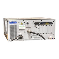
YASKAWA MOTOMAN FS100 Maintenance Manual (348 pages)
Brand:
YASKAWA
| Category:
Controller
| Size: 13.42 MB
Table of Contents
Notes for Safe Operation
5
Definition of Terms Used Often in this Manual
7
Description of the Operation Procedure
8
Registered Trademark
8
Explanation of Warning Labels
9
Location of Warning Labels
9
Warning Labels
9
Mechanical Safety Devices
10
Safeguarding Tips
10
Programming, Operation, and Maintenance Safety
11
Maintenance Safety
12
Summary of Warning Information
12
Customer Support Information
13
Table of Contents
14
1 Equipment Configuration
18
Arrangement of Units and Circuit Boards
18
Power Flow
19
Signal Flow
20
2 Security System
21
Protection through Security Mode Settings
21
Security Mode
21
Security Mode Descriptions
21
Menu & Security Mode (Sheet 1 of 3)
22
Changing the Security Mode
25
Changing a User ID
27
User ID
27
3 Maintenance and Inspections
29
Daily Inspections
29
Cooling Fan Inspections
31
Emergency Stop Button Inspections
32
Enable Switch Inspections
32
Mode Key with a Switch
32
Battery Inspections
33
4 Preparation before Replacing Parts
34
Creating a Check Program
36
5 Replacing Parts
37
Fuse Replacement
37
Locations of the Fuse
38
Interior Circulation Fan Replacement
39
Replacement Procedures
39
Battery Replacement
40
Replacement Procedure
41
FS100 Replacement
44
Backup Device Preparation
45
Recommended Compactflash
45
Recommended USB Memory
45
System Backup
45
Replacement of the FS100
48
Back View of the FS100
49
Loading the Backup Data
50
6 Recommended Spare Parts
53
List of Accessories
53
Recommended Spare Parts
54
Spare Parts for the FS100
54
7 Operations after Replacing Parts
55
Home Position Calibration
56
Calibrating Operation
58
Registering All Axes at One Time
58
Registering Individual Axes
60
Changing the Absolute Data
61
Clearing Absolute Data
62
Manipulator Home Position
64
Position Deviation Check Using the Check Program
65
Checking of the Check Program
66
Motion of the Check Program
66
Home Position Data Correction
67
Setting the Second Home Position (Check Point)
68
Position Check
70
Purpose of Position Check Operation
70
Alarm Occurrence
71
Pulse Difference Check
71
Procedure for the Second Home Position Setting (Check Point)
72
Procedure after the Alarm
73
8 System Diagnosis
75
Manipulator Model
75
System Version
75
Input/Output Status
76
Universal Input
76
Universal Input Simple Window
76
Universal Input Window
76
Universal Output
77
Universal Output Simple Window
77
Universal Output Window
77
Modifying the Output Status
78
Specific Input
79
Specific Input Simple Window
79
Specified Input Window
79
Specific Output
80
Specific Output Simple Window
80
Specified Output Window
80
RIN Input
81
RIN Input Window
81
Signal Number Search
82
Direct Search on the Universal/Specified Input/Output Window
83
Search from the Menu
84
Relay Number Search
85
Direct Search on the Universal/Specified Input/Output Window
86
Search from the Menu
87
Modification of the Signal Name
88
Direct Modification on the Universal/Specified Input/Output Window
88
Modification from the Menu
89
System Monitoring Time Display
90
System Monitoring Time Display Window
90
Individual Window of the System Monitoring Time Display
91
Clearing the System Monitoring Time Display
92
Alarm History
93
Alarm History Window
93
Clearing the Alarm History
94
I/O Message History
95
I/O Message History Window
95
Clearing the I/O Message History
96
Position Data When Power Is Turned ON/OFF
97
Power ON/OFF Position Window
97
Current Position
98
Current Position Window
98
Servo Monitor Window
99
Changing the Monitor Items
100
Clearing Maximum Torque Data
102
Alarm
103
Alarm Code Classification
103
Outline of Alarm
103
Servo Monitoring
99
9 Alarm
104
Alarm Display
104
Displaying and Releasing Alarm
104
Minor Alarms
104
Releasing Alarms
104
Binary Data
105
Decimal Data
105
Special Alarm Display
105
Sub Data
105
Independent Control Function
106
Display of Alarm Details
107
Display of Alarm Detail Window
107
Page
107
ALARM DETAIL Window
109
Standard
109
Transition of Alarm Detail Window
109
Alarm Message List
110
10 Error
321
Error Message
321
System and General Operation
322
Editing
325
Job Defined Data
326
External Memory Equipment
329
Concurrent I/O
334
Maintenance Mode
335
Particular Error Message
336
Fatal Error
336
Application Transaction Error
337
Other Errors
338
When the Error Is Indicated
338
11 LED Indicator on each Circuit Board
339
Before the Check of LED Indicator
339
6 LED-Spot Indicator on the Main CPU Circuit Board
340
Segment LED Indicator on the Main CPU Circuit Board (CPU201R)
341
Status of 7-Segment LED Indicator at Error Occurrence
342
Status of 7-Segment LED Indicator at Control Power Start-Up (One Digit)
343
Status of 7-Segment LED Indicator at Alarm Occurrence
344
7 SEG-LED Indicator on Machine Safety Board (SF2300)
345
7 SEG-LED Indicator on SERVO Control Board (IFM)
346
During the Start-Up Process
347
Advertisement
YASKAWA MOTOMAN FS100 Maintenance Manual (336 pages)
Brand:
YASKAWA
| Category:
Network Router
| Size: 2.54 MB
Table of Contents
Table of Contents
8
1 Equipment Configuration
12
Arrangement of Units and Circuit Boards
12
Power Flow
13
Signal Flow
14
2 Security System
15
Protection through Security Mode Settings
20
User ID
21
Changing a User ID
21
3 Maintenance and Inspections
23
Daily Inspections
23
Cooling Fan Inspections
25
Emergency Stop Button Inspections
26
Enable Switch Inspections
26
Battery Inspections
27
4 Preparation before Replacing Parts
28
Creating a Check Program
30
5 Replacing Parts
31
Fuse Replacement
31
Interior Circulation Fan Replacement
33
Battery Replacement
34
6 Recommended Spare Parts
38
List of Accessories
38
Recommended Spare Parts
39
7 Operations after Replacing Parts
40
Home Position Calibration
41
Calibrating Operation
43
Registering All Axes at One Time
43
Registering Individual Axes
45
Changing the Absolute Data
46
Clearing Absolute Data
47
Manipulator Home Position
49
Position Deviation Check Using the Check Program
50
Checking of the Check Program
51
Motion of the Check Program
51
Checking of the Check Program
52
Home Position Data Correction
52
Setting the Second Home Position (Check Point)
53
Purpose of Position Check Operation
55
Procedure for the Second Home Position Setting (Check Point)
57
Procedure after the Alarm
58
8 System Diagnosis
60
System Version
60
Manipulator Model
60
Input/Output Status
61
Universal Input
61
Universal Input Simple Window
61
Universal Input Window
61
Universal Output
62
Universal Output Simple Window
62
Universal Output Window
62
Modifying the Output Status
63
Specific Input
64
Specific Input Simple Window
64
Specified Input Window
64
Specific Output
65
Specific Output Simple Window
65
Specified Output Window
65
RIN Input
66
RIN Input Window
66
Direct Search on the Universal/Specified Input/Output Window
67
Signal Number Search
67
Direct Search on the Universal/Specified Input/Output Window
68
Search from the Menu
69
Direct Search on the Universal/Specified Input/Output Window
70
Relay Number Search
70
Direct Search on the Universal/Specified Input/Output Window
71
Search from the Menu
72
Direct Modification on the Universal/Specified Input/Output Window
73
Modification of the Signal Name
73
Modification from the Menu
74
System Monitoring Time Display
75
System Monitoring Time Display Window
75
Individual Window of the System Monitoring Time Display
76
Clearing the System Monitoring Time Display
77
Alarm History
78
Alarm History Window
78
Clearing the Alarm History
79
I/O Message History
80
I/O Message History Window
80
Search
80
Clearing the I/O Message History
81
Position Data When Power Is Turned ON/OFF
82
Power ON/OFF Position Window
82
Current Position
83
Current Position Window
83
Servo Monitoring
84
Servo Monitor Window
84
Changing the Monitor Items
85
Clearing Maximum Torque Data
87
9 Alarm
88
Outline of Alarm
88
Alarm Display
89
Displaying and Releasing Alarm
89
Releasing Alarms
89
Special Alarm Display
90
Display of Alarm Details
92
Parameter
92
Display of Alarm Detail Window
92
Transition of Alarm Detail Window
94
Alarm Message List
95
10 Error
305
System and General Operation
306
Editing
309
Job Defined Data
310
External Memory Equipment
313
Concurrent I/O
318
Maintenance Mode
319
Particular Error Message
320
Application Transaction Error
321
When the Error Is Indicated
322
11 LED Indicator on each Circuit Board
323
LED-Spot Indicator on the Main CPU Circuit Board (CPU201R)
324
Segment LED Indicator on the Main CPU Circuit Board (CPU201R)
325
Status of 7-Segment LED Indicator at Error Occurrence
326
Status of 7-Segment LED Indicator at Control Power Start-Up (One Digit)
327
Status of 7-Segment LED Indicator at Alarm Occurrence
328
SEG-LED Indicator on Machine Safety Board (SF2300)
329
SEG-LED Indicator on SERVO Control Board (IFM)
330
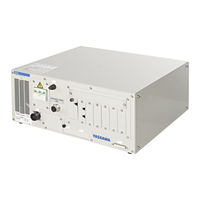
YASKAWA MOTOMAN FS100 Instructions Manual (246 pages)
OPTIONS
Brand:
YASKAWA
| Category:
Controller
| Size: 1.47 MB
Table of Contents
Table of Contents
7
Fs100
10
1 Outline of INFORM
10
About INFORM
10
Inform III
10
Type of Instruction
10
Instruction Set
11
Selecting Instruction Set
11
Variables to be Used in Instructions
13
Set Value of Variable and Numeric Data
13
Registration of Instructions
14
Registration
14
Learning Function
15
Detail Edit Window
16
Registration of Expression
17
Expression
17
Registration
19
INFORM Structure
21
Example of Structure
21
INFORM Structure Elements
22
Meaning of INFORM Structure
22
Explanation Table
23
2 INFORM Explanation
24
I/O Instructions
24
Dout
24
Din
27
Wait
30
Pulse
34
Aout
37
Aration
38
Aratiof
42
Antout
43
Control Instruction
48
Jump
48
Call
52
Getarg
66
Timer
68
(Label)
69
(Comment)
70
Ret
71
Nop
74
Pause
75
Cwait
76
Msg
77
Advinit
78
Advstop
79
Print
80
Cls
84
Abort
85
Setualm
86
Dialog
88
Dialsb
92
Operating Instruction
95
Clear
95
Inc
99
Dec
101
Set
103
Add
112
Sub
119
Mul
126
DIV
133
Cnvrt
140
And
143
Not
147
Xor
149
Mframe
151
Sete
153
Gete
155
Gets
157
Sqrt
163
Sin
165
Cos
167
Atan
169
Mulmat
171
Invmat
173
Setreg
175
Getreg
177
Move Instruction
178
Movj
178
Movl
189
Movc
198
Imov
208
Speed
215
Refp
218
Shift Instruction
222
Sfton
222
Sftof
226
Mshift
228
Instruction Which Adheres to an Instruction
231
Until
241
Enwait
243
General-Purpose Instruction
244
Toolon
244
Toolof
245
Advertisement
YASKAWA MOTOMAN FS100 Instructions Manual (104 pages)
OPTIONS For MotoFit Function Engineering Support Tool
Brand:
YASKAWA
| Category:
Controller
| Size: 12.48 MB
Table of Contents
Table of Contents
9
1 Outline of Function
11
Motofit Function Engineering Support Tool
11
Automatic Adjustment Function of Force Control Parameter
12
Force Control
12
Adjustment Method
13
Motofit Teach Guidance Function
15
Function for Calculation of Force Detection Threshold
16
2 System Configuration
17
3 Operation Procedure
18
Installing / Uninstalling FSE-Tool
18
Installing FSE-Tool
18
Uninstalling FSE-Tool
18
Setting the IP Address
19
Operation for Creating Fitting JOB
22
Outline of Operation Step
22
Detailed Operation Step
23
Startup of FSE-Tool
23
Setting Force Condition File
25
Automatic Adjustment of Force Control Parameter
30
TOUCH Command Teach
42
FIT Command Teach
50
INSERT Command Teach
56
Creating Motofit JOB
64
Chage of Unit Scale (Only for the FS100)
70
Teach of Force Sense Basic Command
71
Outline of Teach Operation of Force Sense Basic Command
71
Details of Teach Operation of Force Sense Basic Command
71
Creating JOB
71
Threshold Setting by Data Logging
73
Operation Check
78
4 Interface Panel
79
5 Monitor Information
81
6 Operation Condition Data
90
Force Condition File Data
90
Adjustment Condition Data
91
Motofit Command Argument Data
92
Backup of Teach Data
95
Data for Setting Detection Threshold
97
7 Error of Automatic Adjustment Function of Force Control Parameter
99
8 Alarm List of FSE-Tools
100
9 How to Check the Version
102
10 Precautions
103
Operation During Force Control
103
Cancel Operation During Execution of Adjustment Operation or Motofit Function
103
Communication Error
103
Limitation Due to Using Environment
103
YASKAWA MOTOMAN FS100 Instructions Manual (39 pages)
OPTIONS FOR INTERFACE PANEL FUNCTION, Industrial Robot Arms
Brand:
YASKAWA
| Category:
Controller
| Size: 5.5 MB
Table of Contents
Table of Contents
7
1 Outline of Interface Panel Function
8
2 Display and Operations of Panel Screen
9
Interface Panel Display
9
Panel Screen Display
9
Panel Screen Operation by Touch Panel
10
Panel Screen Operation by PP Keys
11
Numeric Display
12
Input of Numeric Value
12
Change of Panel Screen
13
Change of Language on Screen
13
3 Data Setting and Touch Panel I/F Instructions
14
Setting Procedure
15
I/F Panel Setting Data and Display Position
16
Editing of Setup
17
Editing of Panel Type
17
Editing of Panel Color
18
Editing of Panel Name
18
Editing of Text Color
19
Editing of Security
19
Editing of Interlock Enable
20
Editing of Input
21
Initialization of Set Data
24
Details on Interface Panel Setting Items
25
4 Save and Load of Set Data
30
5 Editing Saved Data
32
6 Parameters
35
Clearing the Status of Signals
35
Status of General Output Signals at Mode Change
36
Status of General Output Signals at Power Supply on
36
Status of Auxiliary Relay Signals at Power Supply on
37
Status of I/F Panel Signals at Power Supply on
37
Allocation of General Input Signals to Interface Panel Screens
38
Notification of the Status of General Input Signals
38
YASKAWA MOTOMAN FS100 Instructions Manual (28 pages)
FOR CONVEYOR COORDINATED FUNCTION
Brand:
YASKAWA
| Category:
Controller
| Size: 1.28 MB
Table of Contents
Table of Contents
11
1 Conveyor Coordinated Function
12
Configuration of Conveyor Coordinated Function
12
2 Setting
15
Setting the Mechanical Specification for the Conveyor Coordinated Axis
15
Confirmation of the "Mechanical Specifications" of the Station Axis
15
Setting Conveyor Coordinate Mechanical Specification
17
Setting for the Conveyor Synchronization Operation
19
Conveyor Condition File
19
Conveyor Home Position Signal (LS Signal)
20
3 Conveyor Coordinated Axis Operation
21
4 Job Example
22
System Configuration
22
Conveyor Coordinated Axis Job
23
Manipulator Job
25
Master Job
26
5 Supplementary Contents
27
Adjusting the Conveyor Coordinated Axis Accuracy
27
YASKAWA MOTOMAN FS100 Instructions Manual (21 pages)
OPTIONS FOR ANALOG OUTPUT FUNCTION CORRESPONDING TO SPEED
Brand:
YASKAWA
| Category:
Robotics
| Size: 1.44 MB
Table of Contents
Table of Contents
7
1 Analog Output Function Corresponding to Speed
8
2 Instructions
9
Instructions for Analog Output Function Corresponding to Speed
9
Aration
9
Aratiof
10
Registration of Instructions
11
Aration
11
Aratiof
13
Analog Output Display
14
3 Examples
15
Examples of Output Characteristics
15
Example of Variation of Operating Speed and Analog Output Value
16
4 Filter Process
17
When Parameter Is Set to "0
17
When Parameter Is Set to Values Other than "0
17
Parameter Setting
18
5 Precautions
20
When Analog Output Corresponding to Speed Is Interrupted
20
When more than One Manipulator Is Used
20
YASKAWA MOTOMAN FS100 Instructions Manual (26 pages)
OPTIONS, FOR PMT FUNCTION
Brand:
YASKAWA
| Category:
Controller
| Size: 2.29 MB
Table of Contents
PMT Function
8
Data Conversion by PMT Function
9
PMT Data Conversion by Programming Pendant
10
PMT Data Conversion by Instruction
12
Registering SETTOOL Instruction
13
Registering PMT Instruction
14
PMT Data Conversion by Programming Pendant
17
Parameter
20
Tool Data Backup History
21
Instruction List for PMT Function
22
Alarm List
24
YASKAWA MOTOMAN FS100 Instructions Manual (20 pages)
OPTIONS, FOR I/O TRACE FUNCTION
Brand:
YASKAWA
| Category:
Controller
| Size: 1.56 MB
Table of Contents
Table of Contents
7
1 O Trace Function
8
2 Basic Specifications
9
3 Setup of I/O Trace
10
Window
10
Operation Procedure
11
System I/O Signal
12
System Input Signal
12
System Output Signal
12
4 O Trace Log Data
13
Window
13
Operation Procedure
14
5 External Memory
16
Operation Procedure
16
Data Format
17
6 O Traceviewer (Optional)
18
YASKAWA MOTOMAN FS100 Option Addendum (20 pages)
Robot Controller
Brand:
YASKAWA
| Category:
Controller
| Size: 0.43 MB
Table of Contents
Table of Contents
3
FS100 Standard I/O LIO-08R Circuit Board - Connector CN2
5
FS100 Standard I/O LIO-08R Circuit Board - Connector CN1
6
FS100 Expanded I/O LIO-08R-A Circuit Board - Connector CN-2A
8
FS100 Expanded I/O LIO-08R-A Circuit Board - Connector CN-1A
9
N/A Input Common
11
FS100 Expanded I/O LIO-08R-B Circuit Board - Connector CN-2B
11
FS100 Expanded I/O LIO-08R-B Circuit Board - Connector CN-1B
12
N/A Input Common 2_24V
14
FS100 Expanded I/O LIO-08R-C Circuit Board - Connector CN2-C
14
Input Common 4
15
FS100 Expanded I/O LIO-08R-C Circuit Board - Connector CN1-C
15
FS100 Expanded I/O LIO-08R-D Circuit Board - Connector CN2-D
17
Input Common 3_24V
18
FS100 Expanded I/O LIO-08R-D Circuit Board - Connector CN1-D
18
Yaskawa MOTOMAN FS100 Operator's Manual (20 pages)
Brand:
Yaskawa
| Category:
Controller
| Size: 2.61 MB
Table of Contents
Table of Contents
7
1 Outline
8
2 Logging Function
9
Data to be Logged
9
3 Operation
11
List of Log
12
Display of Detailed Log
13
Update of Logging Information
16
Delete of Logging Information
17
Selecting Operation to be Logged
18
YASKAWA MOTOMAN FS100 Instructions Manual (15 pages)
OPTIONS
Brand:
YASKAWA
| Category:
Robotics
| Size: 1.48 MB
Table of Contents
Table of Contents
2
1 System Configuration
3
2 Axis Operation
4
Control Point Fixed Motion During Base Axis Operation
4
Control Point Fixed Base Axis Operation for Single Arm
6
Control Point Fixed Base Axis Operation for Dual- Arm
8
Axis Operation in Cartesian Coordinate System
10
Setting Method
11
3 Job Configuration
13
4 Note
14
YASKAWA MOTOMAN FS100 Instructions Manual (17 pages)
Brand:
YASKAWA
| Category:
Controller
| Size: 0.6 MB
Table of Contents
Notes for Safe Operation
3
Registered Trademark
6
Manual Brake Release
11
Warning Message
16
YASKAWA MOTOMAN FS100 Instructions Manual (12 pages)
FOR I/O JOG OPERATION IN PLAY-MODE MOTOMAN
Brand:
YASKAWA
| Category:
Controller
| Size: 0.69 MB
Table of Contents
Table of Contents
7
Outline
8
Operating Conditions
8
Input Signals for I/O JOG Operation
9
Output Signals for I/O JOG Operation
10
Signal Allocation Setting Display for I/O JOG Operation
11
Advertisement
Related Products
YASKAWA FSP Series
YASKAWA FS100L
YASKAWA FSDrive-MV1000 Series
Yaskawa F Series
YASKAWA FSDrive-MV1S
yaskawa Varispeed f7
YASKAWA FM 250S
YASKAWA FM 054
YASKAWA VIPA SLIO FM 050S
YASKAWA Varispeed F7S
YASKAWA Categories
Controller
DC Drives
Servo Drives
Robotics
Control Unit
More YASKAWA Manuals
Login
Sign In
OR
Sign in with Facebook
Sign in with Google
Upload manual
Upload from disk
Upload from URL