Sign In
Upload
Manuals
Brands
Xantrex Manuals
Power Supply
XFR 20-130
Xantrex XFR 20-130 DC Power Supply Manuals
Manuals and User Guides for Xantrex XFR 20-130 DC Power Supply. We have
1
Xantrex XFR 20-130 DC Power Supply manual available for free PDF download: Operating Manual
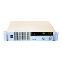
Xantrex XFR 20-130 Operating Manual (90 pages)
XFR 2800 Watt Series Programmable DC Power Supply
Brand:
Xantrex
| Category:
Power Supply
| Size: 1.52 MB
Table of Contents
Power Supply
1
About this Manual
9
Manual Revisions
9
Table of Contents
11
List of Figures
13
List of Tables
15
Description
17
Features and Specifications
17
Features and Options
17
Section 1. Description
17
Front Panel Controls
19
Figure 1.1 Power Supply Front Panel
19
Rear Panel Connectors and Switch
20
Figure 1.2 Power Supply Rear Panel
21
Figure 1.3 Programming and Monitoring SW1 Switch
22
Rear Panel SW1 Switch
22
Figure 1.4 Programming and Monitoring J2 Connector
24
Rear Panel J2 Connector
24
Specifications
27
Electrical Specifications
27
Additional Specifications
32
Input Conditions
32
Figure 1.5 Typical Input Current Characteristics
32
Additional Features
33
Remote Programming and Monitoring
33
Environmental Specifications
34
Mechanical Specifications
35
Figure 1.6 Dimensional Drawings
36
Introduction
37
Basic Setup Procedure
37
Section 2. Introduction
37
Inspection, Cleaning, and Packaging
38
Initial Inspection
38
Periodic Cleaning
38
Returning Power Supplies to the Manufacturer
39
Return Material Authorization Policy
39
Packaging for Shipping or Storage
40
Figure 2.1 Shipping or Storage Carton Label
40
Location, Mounting, and Ventilation
41
Rack Mounting
41
Ventilation
41
AC Input Power
42
AC Input Connector and Voltage Selection
42
AC Input Cord
42
AC Input Wire Connection
43
Figure 2.2 AC Input Cover and Strain Relief
44
Functional Tests
45
Equipment Required
45
Power-On Check
45
Voltage Mode Operation Check
45
Current Mode Operation Check
46
Front Panel Function Checks
46
Load Connection
47
Load Wiring
47
Making Load Connections
48
Figure 2.3 Maximum Load Wire Length for 1 V Line Drop
48
Figure 2.4 Output Strain Relief and Cover
49
Figure 2.5 Typical Load Connection Hardware
50
Figure 2.6 Output Voltage Connector
51
Inductive Loads
52
Connecting Single Loads
52
Figure 2.7 Single Load with Local Sensing (Default)
52
Figure 2.8 Single Load with Remote Sensing
52
Connecting Multiple Loads
53
Figure 2.9 Multiple Loads with Local Sensing
53
Figure 2.10Multiple Loads with Remote Sensing
54
Local and Remote Sensing
55
Sense Wiring
55
Local Sensing
55
Figure 2.11 J10 Sense Connector
56
Using Remote Sensing
57
Figure 2.12Connecting Remote Sense Lines
58
Introduction
59
Local Operation
59
Standard Operation
59
Operating Modes and Automatic Crossover
59
Section 3. Introduction
59
Figure 3.1 Operating Modes
60
Shipped Configuration (Local Control Mode)
61
Setting Output Voltage and Current Limit
62
Using over Voltage Protection (OVP)
63
Front Panel OVP Operation
63
Resetting the OVP Circuit
64
Using the Shutdown Function
65
STANDBY Switch
65
Controlling the Shutdown Function Via the J2 Connector
65
Using Multiple Supplies
67
Configuring Multiple Supplies for Series Operation
67
Configuring Multiple Supplies for Parallel Operation
68
Figure 3.2 Series Operation of Multiple Supplies
68
Configuring Multiple Supplies for Split Supply Operation
69
Figure 3.3 Parallel Operation of Multiple Supplies
69
Figure 3.4 Split Supply Operation of Multiple Supplies
70
Figure 3.5 Split Supply Operation of Multiple Supplies
71
Over Temperature Protection (OTP)
72
User Diagnostics
73
Emergency Shutdown
73
Unusual or Erratic Operation
73
Troubleshooting for Operators
73
Introduction
75
Remote Operation
75
Section 4. Introduction
75
Remote Analog Programming of Output Voltage and Current Limit
76
Remote Programming Options
76
Remote Analog Programming Procedure
76
Figure 4.1 Connecting Programming Sources to J2 Connector
79
Remote Monitoring of Output Voltage and Current
80
Readback Signals
80
Introduction
81
Calibration Setup
81
Equipment Required
81
Section 5. Introduction
81
Service Environment and Precautions
81
Accessing Calibration Potentiometers
82
Calibration Calibration Setup
83
Figure 5.1 Programming and Monitoring Calibration Locations
83
Calibrating for Programming Accuracy
84
Voltage Programming Circuit Calibration
84
Current Limit Programming Circuit Calibration
85
Calibrating for Readback Accuracy
86
Output Voltage Monitor Circuit Calibration
86
Output Current Monitor Circuit Calibration
87
Advertisement
Advertisement
Related Products
Xantrex XFR 2800
Xantrex XFR 20-60
Xantrex XFR 7.5-300
Xantrex XFR 150-18
Xantrex XFR 6-200
Xantrex XFR 7.5-140
Xantrex XFR 40-30
Xantrex XFR 60-20
Xantrex XFR 100-12
Xantrex XFR 150-8
Xantrex Categories
Inverter
Power Supply
Battery Charger
Power Pack
Controller
More Xantrex Manuals
Login
Sign In
OR
Sign in with Facebook
Sign in with Google
Upload manual
Upload from disk
Upload from URL