Tektronix VM700T Manuals
Manuals and User Guides for Tektronix VM700T. We have 12 Tektronix VM700T manuals available for free PDF download: Service Manual, Programmer's Manual, User Manual, Instructions Manual, Product Information
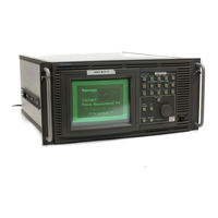
Tektronix VM700T Service Manual (360 pages)
Video Measurement Set
Brand: Tektronix
|
Category: Measuring Instruments
|
Size: 3 MB
Table of Contents
Advertisement
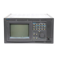
Tektronix VM700T Service Manual (355 pages)
Video Measurement Set
Brand: Tektronix
|
Category: Measuring Instruments
|
Size: 6 MB
Table of Contents

Tektronix VM700T Programmer's Manual (277 pages)
Video Measurement Set RS-232 Interface
Brand: Tektronix
|
Category: Measuring Instruments
|
Size: 0 MB
Table of Contents
Advertisement

Tektronix VM700T User Manual (207 pages)
Video Measurement Set Option 01 NTSC Measurements
Brand: Tektronix
|
Category: Measuring Instruments
|
Size: 1 MB
Table of Contents

Tektronix VM700T User Manual (179 pages)
Video Measurement Set
Option 11 PAL Measurements
Brand: Tektronix
|
Category: Measuring Instruments
|
Size: 1 MB
Table of Contents
Tektronix VM700T User Manual (138 pages)
Video Measurement Set Option 01 (NTSC) & Option 11 (PAL)
Brand: Tektronix
|
Category: Measuring Instruments
|
Size: 1 MB
Table of Contents

Tektronix VM700T User Manual (109 pages)
ideo Measurement Set
Option 40/41/42 Audio Measurements
Brand: Tektronix
|
Category: Measuring Instruments
|
Size: 0 MB
Table of Contents

Tektronix VM700T Programmer's Manual (83 pages)
Video Measurement Set
Option 48 GPIB Interface
Brand: Tektronix
|
Category: Measuring Instruments
|
Size: 0 MB
Table of Contents

Tektronix VM700T Instructions Manual (58 pages)
Video Measurement Set
Brand: Tektronix
|
Category: Measuring Instruments
|
Size: 0 MB
Table of Contents

Tektronix VM700T User Manual (35 pages)
Option 1G Echo And Rounding Errors Measurements
Brand: Tektronix
|
Category: Measuring Instruments
|
Size: 0 MB
Table of Contents

Tektronix VM700T Product Information (17 pages)
Video Measurement Set Option 11 PAL Video Measurements
Brand: Tektronix
|
Category: Measuring Instruments
|
Size: 0 MB
Table of Contents

Tektronix VM700T Instructions Manual (12 pages)
Brand: Tektronix
|
Category: Measuring Instruments
|
Size: 0 MB