
Subscribe to Our Youtube Channel
Related Manuals for Tektronix VM700


Summary of Contents for Tektronix VM700
- Page 1 (217) 352-9330 | Click HERE Find the Tektronix VM700 at our website:...
- Page 2 Service Manual VM700T Video Measurement Set 070-9630-05 Artisan Technology Group - Quality Instrumentation ... Guaranteed | (888) 88-SOURCE | www.artisantg.com...
-
Page 3: Table Of Contents
Table of Contents General Safety Summary ......... . Service Safety Summary . - Page 4 Table of Contents Front Panel Controls ..........2- - 11 Touch Screen .
- Page 5 Table of Contents The Analog-to-Digital (ADC) Board (A3) ......3- - 11 +2.5 V and - - 2.5 V Regulators .
- Page 6 Table of Contents Keypad Board (A10A2) ......... . . 3- - 28 Control Knob .
- Page 7 Table of Contents Audio Board Control ..........3- - 40 Opto-Isolators .
- Page 8 Table of Contents Adjustment Procedure Test Equipment Required ......... . 5- - 1 System Adjustment Procedures .
- Page 9 Table of Contents List of Figures Figure 2- -1: Power line conditioner with a rackmounted VM700T 2- -3 Figure 2- -2: VM700T Startup menu ......2- -5 Figure 2- -3: Touch screen calibration (display) .
- Page 10 Table of Contents Figure 4- -1: VM700T Startup Menu ......4- -1 Figure 4- -2: Instrument run modes menu .
- Page 11 Table of Contents Figure 6- -8: Ferrite forms installed on the Option 41 interconnection cable ..........6- -14 Figure 6- -9: Loosening the screws on the right card cage retainer 6- -16...
- Page 12 Table of Contents Figure 6- -44: Touch screen calibration (display) ....6- -69 Figure 6- -45: Touch screen calibration (panel) ....6- -69 Figure 6- -46: Panel calibration values .
- Page 13 Table of Contents List of Tables Table 1- -1: Input characteristics ......1- -1 Table 1- -2: Digitizer .
- Page 14 Table of Contents Table 1- -38: Line Blanking timing measurements ....1- -17 Table 1- -39: Field Blanking timing measurements ....1- -17 Table 1- -40: Other Timing measurements .
- Page 15 ......... . 1- -31 Table 1- -86: Tektronix automatic audio test measurement specifications .
- Page 16 Table of Contents Table 2- -1: Audio Option 41 connector pin assignments ..2- -20 Table 2- -2: Status indicators ....... . . 2- -21 Table 3- -1: Signals used by VM700T RS-232C ports .
-
Page 17: General Safety Summary
General Safety Summary Review the following safety precautions to avoid injury and prevent damage to this product or any products connected to it. To avoid potential hazards, use this product only as specified. Only qualified personnel should perform service procedures. To avoid potential hazards, use this product only as specified. - Page 18 General Safety Summary Symbols and Terms Terms in this Manual. These terms may appear in this manual: WARNING. Warning statements identify conditions or practices that could result in injury or loss of life. CAUTION. Caution statements identify conditions or practices that could result in damage to this product or other property.
-
Page 19: Service Safety Summary
Service Safety Summary Only qualified personnel should perform service procedures. Read this Service Safety Summary and the General Safety Summary before performing any service procedures. Do Not Service Alone. Do not perform internal service or adjustments of this product unless another person capable of rendering first aid and resuscitation is present. -
Page 20: Preface
10. Replaceable Mechanical Parts List has exploded views and gives the lists of the replaceable mechanical parts to aid in locating a replacement mechanical part. The assembly Tektronix part numbers are also included in this list as a convenience. VM700T Video Measurement Set Service Manual... -
Page 21: Specification
Specification The performance limits in this specification are valid with the following conditions: H This instrument must have been calibrated/adjusted at an ambient tempera- ture between +20_ C and +30_ C. H The instrument must be in an environment with temperature, altitude, humidity, and vibration within the operating limits described in this specification. -
Page 22: Table 1- 2: Digitizer
Specification Table 1- 1: Input characteristics (cont.) Characteristic Performance requirement Supplemental information Clamp Independently programmable on each channel as follows: 1. Timing with respect to sync 2. Clamp pulse width 3. Clamp reference level 4. Clamp time constant Hum Rejection Fast Greater than 24 dB Slow... -
Page 23: Table 1- 3: Synchronization
Specification Table 1- 3: Synchronization Characteristic Performance requirement Supplemental information Modes Video input or external (Sound-in-syncs and PCM2 capable without jumper options.) Amplitudes Internal Minimum - - 14 dB with respect to 286 mV nominal sync amplitude Maximum +12 dB with respect to 286 mV nominal sync amplitude External Minimum... -
Page 24: Physical Characteristics
Specification Physical Characteristics Table 1- 4: Physical characteristics Characteristic Description Dimensions (W × H × D) 19.0 in × 8.75 in × 21.9 in (483 mm × 222 mm × 556 mm) Weight 45 lb (20 kg) Shipping Weight Approximately 71 lb (33 kg) Power Requirements Table 1- 5: Power requirements Characteristic... - Page 25 Specification Table 1- 6: Environmental specification (Cont.) Characteristic Performance requirement Operating 10 Hz - - 55 Hz, 0.015 inch peak-to-peak, 15 minutes total cycling time per axis for three axes followed by a 10 minute dwell at the identified resonance frequency or at 33 Hz if none is found.
-
Page 26: Table 1- 7: Certifications And Compliances
Specification Table 1- 7: Certifications and compliances Category Description EC Declaration of Meets intent of Directive 89/336/EEC for Electromagnetic Compatibility and Low Voltage Directive 73/23/ECC Conformity for Product Safety. Compliance was demonstrated to the following specifications as listed in the Official Journal of the European Communities: EN 55103 Product family standard for audio, video, audio-visual and entertainment... -
Page 27: Table 1- 8: Safety Standards
Specification Table 1- 8: Safety standards Category Description U.S. Nationally Recognized Testing UL3111-1 - - Standard for Electrical and Electronic Measuring and Testing Equipment Laboratory Listing Canadian Certification CAN/CSA C22.2 No. 1010.1 - - Safety Requirements for Electrical Equipment for Measurement, Control and Laboratory Use European Declaration of Conformity Compliance was demonstrated to the following specification as listed in the Official... -
Page 28: Table 1- 10: Rear Panel Signal Connectors
Specification Table 1- 10: Rear panel signal connectors Characteristic Description Port 0 and Port 1 Connectors DB-9, male connectors, configured as RS-232C DTE ports to provide hardcopy output to serial printers and remote control GPIB Connector (Option 48) Meets electrical specifications described in IEEE-488 for parallel GPIB connectors VGA Connector 15 pin, D-type. -
Page 29: Table 1- 11: Optional Power Cords
Specification Table 1- 11: Optional power cords Plug configuration Normal usage Option number North America Standard 125 V/15A Plug NEMA 5-15P Europe 230 V United Kingdom 230 V Australia 230 V North America 230 V Switzerland 230 V European and United Kingdom power cord options A1 and A2 also require the VM700T power line conditioning box for operation in EU countries. -
Page 30: Power Line Conditioner For Option A1 And A2 Power Cords
Specification Power Line Conditioner for Option A1 and A2 Power Cords Table 1- 12: AC Electrical Characteristics Characteristic Description Voltage Range 230 VAC, +10% (207 to 253 VAC), 50/60 Hz, single phase CAT II Maximum Power Consumption 400 VA maximum (250 Watts) with VM700T load Fuse Rating... - Page 31 2000 meters maximum Non-operating Up to 40,000 ft (12,190 m) Shake Tektronix Class 5 Random Vibration Non- - operating Test: For Laboratory/Benchtop Instruments 10 minutes of vibration in each of the 3 major axes including the following levels: 0.0175 g2/Hz from 5 to 100 Hz, - - 3 dB/octave from 100 to 200 Hz.,...
-
Page 32: Pal Measurement Specifications
Specification PAL Measurement Specifications This section lists the specifications for each PAL measurement. The accuracies shown for measurements with averaging capabilities assume the default averaging factor of 32. Test signals of known parameters are provided by characterized and traceable television signal generators to test the accuracy of these derived measurements. -
Page 33: Table 1- 17: Burst Frequency
Specification Table 1- 17: Burst Frequency Measurement Range Relative mode accuracy Burst Frequency ±100 Hz ±0.5 Hz Table 1- 18: Chrominance to Luminance Measurement Range Absolute mode accuracy Relative mode accuracy Chrominance to Luminance Delay ±300 ns ±5 ns ±1.0 ns Chrominance to Luminance Gain Ratio 0 to 160% ±1.0%... -
Page 34: Table 1- 22: Differential Gain And Phase
Specification Table 1- 22: Differential Gain and Phase Measurement Range Absolute mode accuracy Relative mode accuracy Differential Gain (Minimum, Maximum, 0 to 100% ±0.3% ±0.03% and Peak) Differential Phase (Minimum, Maximum, 0 to 360° ±0.3° ±0.03° and Peak) Table 1- 23: Frequency Response and Group Delay Measurement Range Absolute mode accuracy... -
Page 35: Table 1- 26: Incidental Carrier Phase Modulation
Specification Table 1- 26: Incidental Carrier Phase Modulation Measurement Range Accuracy ICPM (requires zero Carrier Pulse and the 0 to 90° ±1.0° quadrature output of the demodulator on Channel C) Table 1- 27: Jitter Measurement Range Absolute mode accuracy Jitter (2 Field) ±20 s ±10 ns Jitter Long Time... -
Page 36: Table 1- 32: Multiburst
Specification Table 1- 32: MultiBurst Measurement Range Absolute mode accuracy Relative mode accuracy MultiBurst Flag Amplitude 0 to 700 mV ±0.5% Packets 1- - 5 (0.5, 1.0, 2.0, 4.0, 4.8 MHz) - - 40 dB to +6 dB ±0.1 dB ±0.03 dB Packet 6 (5.8 MHz) - - 40 dB to +6 dB... -
Page 37: Auto Mode
Specification Table 1- 37: VITS ID Performance Measurement Requirement Supplemental information VITS Recognition Recognizes and displays the name of recognized signals in the vertical interval of both Field 1 and Field 2, lines 15 through 20. VITS test signals recognized are: GCR 8 Fields Seq. - Page 38 Specification Table 1- 40: Other Timing measurements Measurement Range Accuracy ITS Element Standard Bar Rise Time 120 ns to 300 ns ±20 ns Measured from 10% to 0.3 s to 1.0 s ±30 ns 90% points Table 1- 41: Amplitude and Phase measurements Measurement Range Accuracy...
- Page 39 Specification Table 1- 41: Amplitude and Phase measurements (cont.) Measurement Range Accuracy ITS Element Standard Burst Quadrature ±1° Error Differential Gain 0 to +100% ±0.3% CCIR Rec. 569 (Peak and p-p) (0% nominal Differential Phase 0 to 360° ±0.3° CCIR Rec. 569 (Peak and p-p) (0°...
- Page 40 Specification Table 1- 44: Low Frequency Error Measurement Range Accuracy Standard Low Frequency Error (reported as: 0% to 25% CCIR Rec. 569 ±0.8% CCIR LF Error 50- - 550 Hz LF Error (0% nominal) 10- - 1000 Hz LF Error) Table 1- 45: Noise measurements Measurement Range...
-
Page 41: Ntsc Measurement Specifications
Specification NTSC Measurement Specifications This section lists the specifications for each NTSC measurement. The accuracies shown for measurements with averaging capabilities assume the default averaging factor of 32. Test signals of known parameters are provided by characterized and traceable television signal generators to test the accuracy of these derived measurements. - Page 42 Specification Table 1- 50: Chrominance-to-Luminance Gain and Delay Measurement Range Absolute mode accuracy Relative mode accuracy Chrominance to Luminance Delay ±300 ns ±5 ns ±1.0 ns Chrominance to Luminance Gain Ratio 0 to 160% ±1.0% ±0.1% Table 1- 51: Chrominance Frequency Response Measurement Range Absolute mode accuracy...
- Page 43 Specification Table 1- 55: SMPTE color bar nominal values (Cont.) Color LUM (mV) Chroma P–P (mV) Phase (degrees) Green 345.9 588.5 240.8 Magenta 256.7 588.5 60.8 202.2 630.1 103.4 Blue 108.1 444.2 347.1 Table 1- 56: Differential Gain and Phase Measurement Range Absolute mode accuracy...
- Page 44 Specification Table 1- 59: Horizontal Timing (cont.) Measurement Range Absolute mode accuracy Sync to Setup 8.8 s to 13.0 s ±10 ns Breezeway (FCC) 0.1 s to 5 s ±25 ns Sync Level 20 IRE to 80 IRE ±0.5% Table 1- 60: Incidental Carrier Phase Modulation Measurement Range Absolute mode accuracy...
- Page 45 Specification Table 1- 65: Luminance Non-Linearity Measurement Range Absolute mode accuracy Relative mode accuracy Luminance Non-Linearity 0 to 100% ±0.4% ±0.2% Table 1- 66: Multiburst Measurement Range Absolute mode accuracy Relative mode accuracy Reference Flag or Packet Amplitude 30 IRE to 130 IRE ±1% Other Packets (0.5, 1.25, 2.0, 3.0, 3.58, –40 dB to +6 dB...
-
Page 46: Auto Mode
Specification Table 1- 71: VITS ID Measurement Performance requirement Supplemental information VITS Recognition Recognizes and displays the name of recognized signals in the vertical interval of both Field 1 and Field 2, lines 15 through 20. VITS test signals recognized are: GCR 8 Fields Seq. - Page 47 Specification Table 1- 74: RS-170A vertical blanking interval Measurement Range Accuracy Test signal Equalizing Pulse Width 1 s to 20 s ±10 ns Vertical Blanking Serration Width 1 s to 20 s ±10 ns Vertical Blanking Vertical Blanking Width 19 lines to 29 lines –0.1 line to +0.2 line Vertical Blanking Table 1- 75: FCC horizontal blanking interval timing...
- Page 48 Specification Table 1- 77: Amplitude and Phase measurements (cont.) Measurement Range Accuracy Test signal Differential Phase 0 to 360° FCC/NTC–7 Composite ±0.3° Luminance Non-linear Distortion 0 to 50% FCC/NTC–7 Composite ±0.4% Relative Burst Gain FCC/NTC–7 Composite ±100% ±0.3% Relative Burst Phase ±180°...
- Page 49 Specification Table 1- 80: Color Bar measurements Measurement Range Accuracy Test signal Color Bar Amplitude Errors ±100% of nominal ±1.0% FCC Color Bars Color Bar Phase Errors ±180° from nominal ±0.5° FCC Color Bars Color Bar Chrominance to Luminance Gain 0 to 200% of nominal ±2% FCC Color Bars...
- Page 50 Specification Table 1- 83: VIRS measurements (cont.) Measurement Range Accuracy Test signal VIRS Chrominance Phase Relative to Burst ±180° VIRS ±0.5° VIRS Luminance Reference 30% to 100% of Bar ±0.2% (±0.2 IRE) VIRS (30 IRE to 100 IRE when bar is not used) Table 1- 84: Signal-to-Noise Ratio measurements Measurement Range...
-
Page 51: Audio Option 40, Option 41, And Option 42 Specifications
Specification Audio Option 40, Option 41, and Option 42 Specifications The following tables give the specifications for the audio measurements. Automatic Audio Test Specifications Table 1- 85: O.33 Automatic audio test measurement specifications Measurement Range Accuracy (includes flatness) Insertion Gain Error ±6 dB ±0.2 dB Sweep Gain (Min and Max) -
Page 52: Audio Analyzer Specifications
Specification Table 1- 86: Tektronix automatic audio test measurement specifications Measurement Range Accuracy (includes flatness) Insertion Gain Error ±6 dB ±0.2 dB Sweep Gain (Min and Max) 12 dB ±0.1 dB THD + N ≤ 0.03% to 70% ±10% ± 1 digit Crosstalk (into channel) ±1 dB... - Page 53 Specification Table 1- 87: Frequency and Noise specifications (Cont.) Measurement Specification Comments Resolution 0.1 dB Frequency Range 20 Hz to 20 kHz Accuracy ±1 Hz for input ≥ - - 60 dBu Resolution ±1 Hz for input ≥ - - 60 dBu Phase Difference Minimum input level for - - 40 dBu...
-
Page 54: Audio Spectrum Specifications
Specification Audio Spectrum Specifications Table 1- 89: General Audio Spectrum specifications Specification Normal Res mode High Res mode Description Display bandwidth DC to 24 kHz Any 3 kHz within the display bandwidth Frequency resolution 47 Hz 6 Hz Cursor readout accuracy Frequency ±... -
Page 55: Multitone Analyzer Specifications
Specification Table 1- 92: Miscellaneous specifications Description Specification Channel separation/crosstalk > 100 dB 20 Hz to 20 kHz Input connectors ® Option 40 Two mini-XLR (Switchcraft TY3F); requires Switchcraft TA3M mini-XLR plug Two mini-XLR to XLR female adapters and two mini-XLR male plugs are supplied. One male DB- - 37 connector. -
Page 56: A/V Timing Specifications (Option 42)
Specification Table 1- 93: Multitone Analyzer measurement specifications (cont.) Description Specification Comments Minimum Amplitude of Reference Tone for Multitone Recognition Input Range Window - - 10 dBu - - 20 dBu - - 30 dBu - - 40 dBu - - 50 dBu AUTO RANGE - - 50 dBu Minimum Multitone Recognition Time... -
Page 57: Table 1- -5: Power Requirements
Specification Table 1- 95: IEEE 488.1 interface functions implemented in the VM700T GPIB interface card Function Implemented Notes Source Handshake Complete capability Acceptor Handshake Complete capability Talker Basic Talker, Serial Poll, Unaddr if MLA Talker (extended) No capability Listener Basic Listener, Unaddr if MTA Listener (extended) No capability Service Request... -
Page 58: Option 1S Sdi Specification
Item Description GPIB Cable 1 m, double-shielded. Tektronix Part No. 012- - 0991- - 01 2 m, double-shielded. Tektronix Part No. 012- - 0991- - 00 3 m, double-shielded. Tektronix Part No. 012- - 0991- - 02 GURU II+. GPIB User’s... - Page 59 Specification Table 1- 99: SDI Eye Diagram application (cont.) Characteristic Performance requirement Supplemental information Full temperature range 10% for signals between 600 mV and 1 V 20% to 80% Rise Time Accuracy 100 ps for rise times between 400 ps and 1.5 ns Signal Aberrations <5% for 800 mV...
- Page 60 Specification Table 1- 100: SDI Jitter application (cont.) Characteristic Performance requirement Supplemental information 270 Mb/s, 360 Mb/s 3 dB to 5 MHz; +3 dB to - - 6 dB at 10 MHz - - 3 dB at 8 MHz typical Timing &...
- Page 61 Specification Table 1- 103: SDI Audio/Video Timing application Characteristic Performance requirement Supplemental information Embedded Signal Accuracy 200 s Range 2 seconds; less range on data streams heavily loaded with ancillary data External Signal Accuracy 200 s Range 2 seconds 1- 41 VM700T Video Measurement Set Service Manual Artisan Technology Group - Quality Instrumentation ...
- Page 62 Specification Table 1- 104: SDI Ch. A Input Characteristic Performance requirement Supplemental information Electrical Characteristics Input type BNC passive loopthrough; 75 Ω compensated Return Loss Power On ≥25 dB, 1 MHz to 360 MHz Channel on or off Power Off ≥15 dB, 1 MHz to 360 MHz Insertion Loss Power On...
- Page 63 Specification Table 1- 105: SDI Ch. B Input Characteristic Performance requirement Supplemental information Electrical Characteristics Input type BNC; 75 Ω terminated Return Loss Power On ≥25 dB, 1 MHz to 360 MHz Channel on or off Power Off ≥15 dB, 1 MHz to 360 MHz Signal Characteristics Amplitude Range 800 mV;...
- Page 64 Specification Table 1- 107: SDI Output Characteristic Performance requirement Supplemental information Electrical Characteristics Output type BNC; 75 Ω compensated Return Loss Power On ≥25 dB, 1 MHz to 360 MHz Channel on or off Power Off ≥15 dB, 1 MHz to 360 MHz Signal Characteristics Amplitude 800 mV...
-
Page 65: Operating Information
Operating Information The VM700T Video Measurement Set is a multi-function television test and measurement device with an easy to use interface. The measurement set performs the functions of a waveform monitor, vectorscope, automatic measurement set, and a noise measurement set on acquired television signals. The measurement set does measurements on video signals obtained from either live TV signals (broadcast or cable) or television test equipment. -
Page 66: Changing Line Voltage Range And Fuse
Operating Information Changing Line Voltage The voltage range selection switch and fuse holder are located in the lower left Range and Fuse corner of the rear panel (see Figure 2- -10 on page 2- -16). The measurement set is shipped from the factory set to the operating voltage of the destination (115 VAC or 230 VAC). -
Page 67: Installing The Power Line Conditioner
Operating Information Installing the Power Line The Power Line Conditioner can be used with either with a rackmounted Conditioner VM700T or a standalone VM700T on a benchtop. Rackmounted VM700T. Use the mounting bracket and screws provided with the accessory to attach the box to a rackmount rail. Use only #10 screws for the screw holes in the box. -
Page 68: Power On Diagnostics
Operating Information Benchtop Mounting. For a standalone VM700T on a benchtop or for portable use, apply the four adhesive rubber feet provided with the accessory to the bottom of the box at the corners. Place the conditioner box in a convenient location where you can make the power cord connections. -
Page 69: Figure 2- 2: Vm700T Startup Menu
Operating Information Calibrating the Touch The measurement set is shipped from the factory with its touch screen fully Screen calibrated. However, if you notice misregistration of the touch screen, you can recalibrate it. Use the following procedure to calibrate the touch screen: 1. -
Page 70: Figure 2- 3: Touch Screen Calibration (Display)
Operating Information --- TOUCH PANEL INTERFACE CAL (DISPLAY) --- Use the knob to adjust horizontal position and squareness of the screen border lines. Press ‘AUTO’ button to abort, or any other to accept and store current setting. Current Setting: 14 Figure 2- 3: Touch screen calibration (display) 5. -
Page 71: Setting The Power On Mode
Operating Information 6. After you have touched the dots at all four corners, a screen showing the panel calibration factors is displayed (see Figure 2- -5). From that screen, you can press any key to return to the startup menu. --- PANEL CALIBRATION VALUES --- XSCALE = 471 XOFFSET = 292... -
Page 72: Measurement Set Operating Modes
Operating Information 2. In Diagnostics Configuration menu, highlight and select P in the Set Diagnostics Powerup Mode line to bring up the powerup mode choices shown in Figure 2- -7. 3. In the Set Diagnostics Powerup Mode menu, either highlight and select Q to have the measurement set skip diagnostics on power up or highlight and select P to have the measurement set run diagnostics on power up. -
Page 73: Vector Mode
Operating Information You can expand the waveform display around any vertical or horizontal point. Since the data is digitized, the display is bright at all expansion factors. The axes automatically expand with the waveform, so all units are correct as displayed. Vector Mode The Vector mode provides the normal vectorscope display. -
Page 74: User-Programmable Functions
Operating Information When you switch between Digital Mode and Analog Mode, the operation of the front-panel buttons does not change except for the following five buttons: Waveform, Vector, Picture, Measure, and Auto. The Waveform and Picture buttons access the SDI Waveform and the SDI Picture applications respectively. The Vector button accesses the SDI Lightning application. -
Page 75: Front Panel Controls
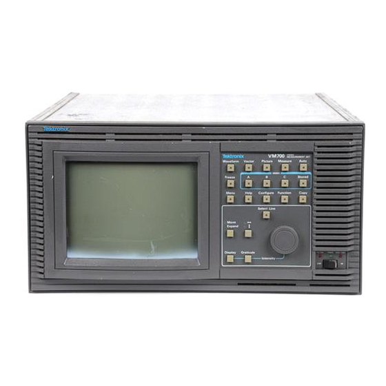
Operating Information Front Panel Controls The front panel controls (shown in Figure 2- -8) consists of a touch screen interface and a 20-button keypad with a control knob. Figure 2- 8: The VM700T Video Measurement Set front panel Touch Screen The display (CRT) area of the measurement set has a touch screen interface for communicating with the measurement set. -
Page 76: Keypad
Operating Information Keypad The keypad (shown in Figure 2- -9) contains three five-button rows, plus an additional five buttons associated with the control knob. Figure 2- 9: Measurement set keypad Manual and Auto Operational Modes. The top row of buttons selects the major functions (operating modes) of the measurement set. - Page 77 Operating Information NOTE. Manual mode parameters do not carry over to Auto mode. You must set parameters for both the Auto mode and the manual modes. The parameter files are reached through the directory and file structure accessed by the Configure button.
- Page 78 Operating Information H Help Button. Pressing the Help button activates the Help function. While Help is activated, pressing a button or selecting a soft key displays a brief explanation of that button or soft key’s function. When the Help function is active, all buttons and soft keys except Help lose their normal function, and the LED on the Help button flashes.
-
Page 79: Control Knob
Operating Information H Select Line Button. The Select Line button changes the function of the control knob from the default Move/Expand action to line selection. The LED in the Select Line button is on when Select Line is active. To scroll through the field line by line, press the Select Line button and rotate the control knob. -
Page 80: Rear Panel And Connections
Operating Information Rear Panel and Connections The rear panel (shown in Figure 2- -10) includes the line voltage and switching module, line voltage selector, fuse holder, a cooling fan, the signal input connectors, the VGA connector, the parallel printer port, and the RS-232 serial ports. - Page 81 Operating Information H Signal Inputs. These are the connections for Channel A, B, and C signal inputs to the measurement set. H External Sync. This input allows you to connect the measurement set to an external sync source. H RS-232 Ports. These ports are the serial interface from the measurement set to a printer for printing displayed data, screens, and logging information.
-
Page 82: Equipment/Video Signal Sources Required
Operating Information Equipment/Video Signal Sources Required Most measurements supported by the measurement set are made using television video signals. The video signals can be from either off-the-air broadcast or looped-through programming signals connected to the rear panel Channel and External Sync inputs (see Figure 2- -11). Non-loop through signals must have the signal output terminated with precision 75 Ω... -
Page 83: Connecting Audio Option 40 To A Source
Operating Information Connecting Audio Option 40 to a Source The VM700T Audio option comes with two male mini-XLR to female XLR adapter cables wired as shown in Figure 2- -12. The mini-XLR ends of these cables connect the Audio option input to an appropriate audio signal source. Female XLR to male mini-XLR adapter cable Figure 2- 12: Cables and connectors supplied with Audio Option 40 Input Connector Pin... -
Page 84: Connecting Audio Option 41 To A Source
For single-ended input: connect single-ended inputs to a + Signal pin; connect a - Signal pin to shield. Option 41 Audio Signal Tektronix supplies a DB-37 mating connector kit with Option 41 to assemble the Interconnection Cable signal interconnection cabling. The connector pin locations are shown in Figure 2- -14. -
Page 85: Gpib Option 48 Signal Connections And Rear Panel
Operating Information GPIB Option 48 Signal Connections and Rear Panel The Option 48 interface connector is a standard GPIB parallel connection with pin outs adhering to industry standards for location and output signal levels. GPIB Indicator LED Seven LED indicators are mounted on the GPIB board. You can see them at the rear of the measurement set as shown in Figure 2- -15. -
Page 86: Sdi Option 1S Rear Panel Connections
Operating Information SDI Option 1S Rear Panel Connections Figure 2- -16 shows the VM700T rear panel with Option 1S installed. Figure 2- -17 shows a close-up of the Option 1S rear panel. The Option 1S rear-panel connectors provide the following functions: H The SDI Ch. -
Page 87: Figure 2- 16: Vm700T Rear Panel With Option 1S Installed
Operating Information Option 1S rear panel Fan exhaust Power Fuse ON/OFF Line voltage Parallel Alarm RS-232 connector switch selector output printer port connector ports Figure 2- 16: VM700T rear panel with Option 1S installed Figure 2- 17: Option 1S rear panel 2- 23 VM700T Video Measurement Set Service Manual Artisan Technology Group - Quality Instrumentation ... - Page 88 Operating Information 2- 24 VM700T Video Measurement Set Service Manual Artisan Technology Group - Quality Instrumentation ... Guaranteed | (888) 88-SOURCE | www.artisantg.com...
-
Page 89: Theory Of Operation
Theory of Operation This section describes the electrical operation of the VM700T Video Measure- ment Set using the major circuit blocks as modules. This section has two main parts: H Overview of the VM700T System describes the system operation of the modules (circuit boards). - Page 90 Theory of Operation The CPU board (A5) contains a microprocessor, a floating-point unit, real-time clock, Flash EPROM, NVRAM, display memory, and display driver hardware. The display driver hardware converts acquired data to video and drives the VM700T display. A monochrome VGA output to the rear panel is also derived from the display driver hardware The Flash EPROM stores application programs and the NVRAM stores system and configuration files created by the user.
-
Page 91: Module Functional Description
Theory of Operation Module Functional Description This part describes the operation of each circuit board module in the VM700T. Block diagrams accompanying the text show the functions of the modules. Analog Input Board (A1) The analog input board performs input selection and applies bias, clamping, offset, gain, and dither to the input video before digital conversion. -
Page 92: Figure 3- 1: Analog Input Board (A1) Block Diagram
Theory of Operation Clamped Input Amplifier Channel Selection To Filter Switch Board Cal Switch Loop-Through Inputs Chan A Differential Amplifier Chan B Chan C Cal DAC Clamp and Bias Mode Generator Control Sync To Genlock Selection Board Sync Sync Buffer DVM Selection (VFC) Acquisition/... -
Page 93: Differential Amplifier
Theory of Operation Differential Amplifier The differential amplifier combines the differential output of the switching matrix and produces a single-ended video output signal which is connected by coaxial cable to the filter switch board. After being filtered (if filtering is needed) the video signal returns to the analog input board for offset, gain, and dither processing. -
Page 94: Sync Selection
Theory of Operation Sync Selection The VM700T gets sync from one of two sources: H directly from the channel A, B, or C loop-through inputs H from the external sync loop-through input To maintain a high impedance level for the video loop-through inputs, the sync selection buffers the selected signal. -
Page 95: The Genlock Board (A2)
Theory of Operation The Genlock Board (A2) The genlock board sends a constant frequency sampling strobe to the analog-to- digital converter (ADC) board. The NTSC and PAL television standards are supported by both the genlock board and application firmware. A block diagram of the genlock board is shown in Figure 3- -2. -
Page 96: Sync Stripper
Theory of Operation Phase Locked Loop 200 s delay Ramp timeout Coarse Correction Video Composite Sync Sync Horizontal Sync Lock Stripper Status Clock 20.25 MHz clock Sound-in-Sync Clock FH Generator ON/OFF (Sync Async or Phase Sync Window) 20.25 MHz ON/OFF 20.25 MHz Comparator Mode... -
Page 97: Fh Generator
Theory of Operation FH Generator The FH generator provides an NTSC or PAL line-rate frequency reference clock to the phase-locked loop, using either the horizontal sync output from the sync stripper or the line-rate frequency derived from the 20.25 MHz crystal clock. The FH generator also provides a timing reference to the frame decoder. -
Page 98: Output Generator
Theory of Operation Output Generator The output generator provides sampling, line, and frame strobes, to the analog- to-digital converter (ADC) board. Sampling strobe output: A multiplexer selects either the four-times subcarrier (4Fsc) clock from the phase-locked loop or the 20.25 MHz crystal clock. A transparent latch stops the clock output when changing sources, ensuring a smooth transition between them. - Page 99 Theory of Operation The Analog-to-Digital (ADC) Board (A3) +2.5 V and - 2.5 V The +2.5 V and - -2.5 V regulators provide a balanced low-noise power source for Regulators the A/D converter. The +2.5 V source is the output of a 5 V, 3-terminal regulator stacked on the - -2.5 V supply.
-
Page 100: Figure 3- 3: Adc Board Block Diagram
Theory of Operation +2.5VA +15V ADC IN +2.5 V and - - 2.5 V FLATNESS COMP - - 15V TEST POINT VREF REGULATORS ADJUST - - 2.5VA SIGNAL CONDITIONING AMPL ANALOG ADC FILTER GAIN SIGNAL IN ADJUST SIGNAL CONDITIONING AND REGULATORS CONDITIONED ANALOG SIGNAL SIGNAL IN VREF... -
Page 101: Overrange Detector
Theory of Operation Line and Frame Pulse H-sync and V-sync from the GenLock board are applied to the Line and Frame Pipeline Pulse Pipeline. The pipeline is a series of flip-flops that delays the frame and line sync by the same amount as the A/D converter delays the video. Overrange Detector The Overrange detector checks to see if the eight most-significant bits of the 10-bit samples are either all 1’s or all 0’s. -
Page 102: Filter Switch Board (A4)
Theory of Operation Filter Switch Board (A4) The filter switch board performs analog filtering of the video signal. Filtering is performed by one of five filters mounted as daughter boards on the main circuit board. The video signal is intercepted on the analog input board just after channel selection and then returned for analog processing (offset, gain, and dither). -
Page 103: Filter Select And Control
Theory of Operation 1X/8X SELECT SLOT 0 FILTER To/From SELECT & Video to Acquisition/ CONTROL Analog Input Controller Board Board OUTPUT AMPL SLOT 1 FILTER SLOT 2 FILTER SLOT 3 Video from Analog Input FILTER Board SLOT 4 FILTER FILTER SLOT ASSIGNMENTS SLOT 5 1 NTSC BW LIMIT 2 IEEE LOW PASS... -
Page 104: Cpu Board (A5)
Theory of Operation CPU Board (A5) The CPU and CPU I/O boards are the complete central processing core for the VM700T. The CPU board incorporates Flash EPROM program memory, nonvolatile memory for data and user-programmed routines, the front panel interface, and the display driver hardware. The CPU I/O board provides the interface between two RS232 serial ports, one parallel printer port, and the central processor. -
Page 105: Eprom
Theory of Operation EPROM The EPROM is a 16-bit wide device with a maximum allowed memory of 512 Kbytes. This is a read-only memory where the system boot-up code resides. Under normal operation (after the boot sequence is complete) the CPU executes instructions contained in Flash ROM (programmable read-only memory). -
Page 106: Front Panel Processor
Theory of Operation Front Panel Processor A 32-bit microcontroller is used for the front-panel processor. A built-in clock synthesizer generates the required system clock frequency for the front-panel processor and the external interface circuitry. The front panel is scanned for button presses, knob rotation, and touch screen touches. - Page 107 Theory of Operation Table 3- 1: Signals used by VM700T RS-232C ports Signal Notes DCD (Data Required for modem connections only. This signal typically comes Carrier Detect) from a modem and indicates that a phone connection is made. RD (Receive The VM700T receives data on this pin.
-
Page 108: Data Acquisition/Controller Board (A18)
Theory of Operation Data Acquisition/Controller Board (A18) The combined Data Acquisition/Controller board (A18) does both data acquisi- tions and controlling of the acquisition process. The acquisition portion of the board is a programmable data interface between the ADC board and the CPU microprocessor. -
Page 109: Acquisition Control
Theory of Operation VIDEO INPUT MIN-MAX VIDEO CLOCK CLOCK IN DATA BUS INTERFACE ACQUISITION DATA DATA CPU DATA DATA CONTROL IN CONTROL IN FIFO/ DEMULTIPLEXOR ACQUISITION DATA IN ACQUISITION ACQUISITION CONTROL CLOCK IN ACQUISITION DATA OUT CPU CONTROL DATA CLOCK CLOCK IN FIFO OCCUPANCY OCCUPANCY OUT... -
Page 110: Controller Section
Theory of Operation Controller Section The controller portion of the board performs the following functions: H controls the VM700T analog front end H receives and processes digitized data from the ADC board and passes it to acquisition memory H controls acquisition patterns Figure 3- -8 shows a block diagram for the controller circuitry. -
Page 111: Controller Asic
Theory of Operation CPU SYSTEM BUS A24-31 A0-1, A2-11 D0-31 A12-23 ADDRESS CONTROL DECODER DATA ADDRESS BUFFER BUFFER TTL-TO-ECL CONVERTER MODE BD0-31 CONTROL BD16-31 CONTROLLER ASIC BA10-15 SEQUENCER BA0-9 ADDRESS BUFFER FRAME LSYNC BA0-15 STATUS PULSES FROM STATUS CONTROL ACQUISITION DATA COUNTERS BOARD... -
Page 112: Status Counter
Theory of Operation Status Counter A triple timer/counter counts status pulses from the acquisition section of the board. The status pulses may be used by applications to indicate events occurring in an acquisition pattern. ECL-To-TTL Conversion The differential ECL signals from the ADC board (D0-D9, FRAME_OUT, LINE_OUT, CKD, and OVERRANGE) are converted to single-ended TTL outputs before being used by the Acquisition/Controller board. -
Page 113: Dynamic Settings
Theory of Operation Address Register. The normal input to static RAM is the 16 bits from the sequencer address register. The four TRIG bits, the 16-bit counter CARRY bit, and 11 bits (out of 32) from the output of static RAM comprise the 16-bit input to the register. -
Page 114: Figure 3- 9: Dither Generator 64-Step Dither Waveform
Theory of Operation H hold the current level H load a custom six-bit dither value Figure 3- -9 shows the pre-defined dither waveform sequence built into the dither generator. Figure 3- 9: Dither generator 64-step dither waveform When the dynamic settings address buffer is enabled, the CPU microprocessor can read or write the dynamic settings static RAM from the dynamic settings data buffer. -
Page 115: Front Panel Board (A10A1)
Theory of Operation Front Panel Board (A10A1) The front panel board (Figure 3- -10) decodes input from the control knob and touch screen and relays push button and LED information to and from the A10A2 keypad board. The front panel board connector to the display memory board contains most of the lines of the 68008 bus, including lines for relaying push button and LED information to and from the keypad board. -
Page 116: Keypad Board (A10A2)
Theory of Operation Keypad Board (A10A2) The VM700T front-panel push buttons, LED, and the control knob are connected to the keypad board. The keypad board is connected to the front panel board through a flex cable that carries power, the 68008 data bus, enable signals from the front panel board’s address decoder, and two bits of data from the control knob. -
Page 117: Main Interconnect Board (Left And Right) (A11)
Theory of Operation Main Interconnect Board (Left and Right) (A11) The VM700T has both attached assemblies and plug in modules. The plug in modules are supplied with power, data, address, and control signals through the interconnections to the Main Interconnect Board. There is a Left and Right board (for the plug in modules on the left and right sides of the VM700T) and an interconnect board that ties the two sides together. -
Page 118: Horizontal Deflection
Theory of Operation High Voltage +5 V +12 V and +5 V Supply +12 V Brightness Focus Horizontal H Sync Deflection +55 V - - 100 V Horiz + Horiz Position Horiz Sync Horiz - - Video Amplifier +550 V Video In Video Out +12 V... -
Page 119: High Voltage
Theory of Operation High Voltage The high voltage supply provides the CRT anode voltage, the focus voltage, and the +55 V and - -100 V sources. The main focus voltage is set by the FOCUS potentiometer. Dynamic focusing optimizes the edge focusing of the CRT. The dynamic focusing waveform is shaped to produce the best edge focus in conjunction with the setting of the FOCUS pot for best overall focus. -
Page 120: +12 V And 15 V Regulators
Theory of Operation Line Input Secondary Inverter Voltage Power Rectifiers Switching +5 Va Switch Rectifier Circuit - - 5.2 Va +5 V Housekeeping Supply +16.5 V - - 16.5 V +16.5 V HOUSEKEEPING +14.4 V +15 V 12 V & 15 V - - 15 V Regulators Power... -
Page 121: Alarm Sensing
Theory of Operation Alarm Sensing The Alarm Sensing circuitry looks at the various supply voltages to check for undervoltage, overvoltage, overcurrent, and power fail conditions. The status of these conditions are the signals fed to the Alarm Logic circuitry. Alarm Logic Each of the alarm sensing outputs is monitored by the Alarm Logic circuitry. -
Page 122: Audio Processor Interface
Theory of Operation 68020 Program X Data Y Data Data Bus Memory Memory Memory 16K/64K Words Words Words Data Host Port Audio Analog Reset Board Interrupt/ Audio Audio Processor Control Data Interface From Register Register Reset Control Audio Analog Board Figure 3- 14: Audio Processor block diagram Audio Processor Interface The Audio Processor Interface consists of address decoders, bus buffers, and... -
Page 123: Interrupt Generator/Status Port
Theory of Operation Interrupt Generator/Status Port A function of this 32-bit control register is to control interrupts for the DSP (digital signal processor). It consists of an interrupt generator, data buffers, and read/write registers that hold the data for access when needed. Interrupt Generator The interrupt generator contains the interrupt control lines for the DSP. -
Page 124: Audio Data Register
Theory of Operation Audio Data Register This register accepts serial data from the ADC on the analog board and converts it to parallel data for the DSP or the CPU. A serial to parallel converter converts the serial data from either the ADC or the DSP (generated for diagnostics) to a 24-bit parallel data word used by the DSP. -
Page 125: Audio Analog Board (A13)
Theory of Operation Audio Analog Board (A13) The following paragraphs discuss the Audio analog board. Refer to Figure 3- -15 as you read the discussion. Input Amplifiers This section discusses the channel 2 (right channel) input amplifier, but the channel 1 (left channel) input amplifier circuitry and function is the same. The input amplifiers are labeled on the board’s back panel. -
Page 126: Figure 3- 15: Audio Analog Block Diagram
Theory of Operation signal is converted to a single-ended signal and common-mode voltage is suppressed or cancelled. Control From Processor Calibration DAC OPTO (Gain & Offset CAL) Serial OPTO Data LEFT INPUT (Balanced) Differential 3-Pole Input Input Input 20dB Left 400Hz Notch Overload ADC Input... -
Page 127: 400 Hz Notch Filter/Dac Output
Theory of Operation 400 Hz Notch Filter/DAC Output The signal enters on the left and is applied to the contact arm of a relay that switches the notch filter in or out of the Channel 2 signal path. The filter is normally out. -
Page 128: Option 40 A/D Converter
Theory of Operation Option 40 A/D Converter The channel 1 and channel 2 circuits are identical; only the channel 2 circuit is discussed here. Input Clamp The channel 2 signal is applied to a clamp circuit at the input of the amplifier. This clamp circuit protects the input of the A/D converter. -
Page 129: Counter/Decoder
Theory of Operation Analog board input signals to be isolated enter the board through a buffer. The buffer receives its power from the VM700T. The input signals enter through two of the opto-isolators (each device is a dual opto-isolator). The signals sent from the isolators are referenced to analog board ground. -
Page 130: Calibration Dac
Theory of Operation A control signal used to hold off the 2.034 MHz. When the signal is low, the 2.034 MHz is not generated. The signal is generated only when diagnostics are run or when a new control word is written for changing gain or attenuation. Calibration DAC The DAC is an 18-bit D/A converter. -
Page 131: Figure 3- 16: Audio Analog Block Diagram
Theory of Operation input channel switching. The left and right selection relay circuits are identical in operation. For brevity, only the left channel operation is described here. A+ XOR B+ (A+ XOR B+) XOR C+ CH1+ A- - Single Three A- - XOR B- - Left Rear... -
Page 132: Option 48 Gpib Interface Board (A19)
Theory of Operation Option 48 GPIB Interface Board (A19) Figure 3- -17 shows the installed location of the A19 circuit board in a fully optioned instrument. The GPIB Interface Board (A19) contains a GPIB processor, a GPIB controller, Dual Port RAM, and additional circuity to handle communication between the GPIB processor and the VM700T processor and communicate with remote devices through the GPIB bus. -
Page 133: Figure 3- 18: Block Diagram Of The Gpib Interface Option Board
Theory of Operation D0-31 (BR) VM700 Main VM700 Main Processor Processor Dual-Port Decoding Memory Interface BA0-25 D0-31 BA0-25 VM700 BA0-25 Main J100A, B, C Processor to VM700T IA1-2 Address Buffers A0-31 VM700 Main DPRD0-31 Processor Access GPIB Control & Processor... -
Page 134: Figure 3- 19: Gpib Rear Panel Arrangement
Theory of Operation The GPIB processor has no memory cache so it gets its program instructions from the program RAM space. Most of the remaining access time, the GPIB processor is doing reads and writes to and from the shared and private RAM space. -
Page 135: Option 1S Serial Digital Measurements
Theory of Operation Option 1S Serial Digital Measurements Option 1S is composed of three boards: the SDI Rear Panel Interface assembly, the SDI board, and a modified Acquisition Memory board. SDI Rear Panel Interface The SDI Rear Panel Interface assembly contains the low-distortion loopthrough Assembly circuitry for both the SDI Channel A and the Analog Reference inputs. -
Page 136: Figure 3- 20: Option 1S Block Diagram
Theory of Operation Analog Signal Path Digital Signal Path Rear Panel AES/EBU Analog Ch A Ch B Output Digital Audio Time Code Analog AES Audio Equalizer Equalizer LTC Receiver sync stripper Regenerator receiver Analog Channel High-performance Clock Clock line & frame select clock recovery recovery... - Page 137 Theory of Operation Analog/Digital MUX. The analog/digital MUX selects between the Channel A analog data stream and the digital data stream. Audio/Video MUX. The audio/video MUX selects between the analog or digital data stream and the audio data stream. It also has the capability to insert the external audio data stream in place of the SDI chrominance samples of the data stream for A/V timing measurements of external audio.
- Page 138 Theory of Operation Analog Sync Detector. The analog sync detector recovers line and frame sync from the Analog Reference input signal. LTC Receiver. The LTC Receiver block translates the LTC signal into registers that can be read by the CPU. Modified Acquisition The modified Acquisition Memory board contains all the analog circuitry, plus a Memory Board...
-
Page 139: Performance Verification
Performance Verification The Verification procedures in the this section are done with the covers on the measurement set to verify its operation and may be used to determine the need for readjustment. After a board exchange, certain adjustments may be needed to compensate the overall system performance. - Page 140 Performance Verification In the Run Modes Menu, select A - - Auto Reset. This restarts the measurement set and runs the full set of internal diagnostics. Check that all tests pass as they run. If a test fails, refer to the appropriate text in the Maintenance section for further actions you can take to determine which board or boards may be at fault.
- Page 141 Performance Verification H If the Diagnostic measurements are not shown, touch the Diags soft key to switch to them. H Touch the DiagsLoop soft key to loop the selected continuously. H Use the Abort Looping soft key to halt diagnostic looping at the end of the warm up period.
- Page 142 Performance Verification 5. Press the Update & Exit soft key to write out (save) any changes to the file; press the No change & Exit soft key to leave the file as it was when it was last saved. Power Up Diagnostics Selection Genlock~Diagnostic Controller~Diagnostic Acquisition~Diagnostic...
- Page 143 Performance Verification Diagnostic Errors (File) When high-level diagnostics are run, any errors detected are written to the Diagnostic Errors file. The contents of this file can be printed using the Print File soft key, or the file can be deleted using the Delete soft key. If diagnostic errors appear, refer to the Diagnostics information starting on page 6- -55.
-
Page 144: Test Equipment Required
The examples given are based on the test equipment that many customers and the Tektronix service centers have installed for supporting the VM700 family of video measurement sets. Substitute test equipment may be used if available. Refer to the Minimum Specification column to determine the key specifications needed to verify the accuracy of the VM700T Video Measurement Set. -
Page 145: System Verification Procedures
Test Equipment Required H Video amplitude calibration fixture (VAC). Tektronix 067-0916-00. H Coaxial cable, 75 Ω high-quality noise free; 1-meter length. Tektronix 012-0074-00. Procedure: Measure Squarewave 1. Connect the VAC to channel A of the measurement set (leave the input unterminated). - Page 146 H Leveled sine-wave generator, 75 Ω output impedance, output flat within ±0.025 dB (±0.3%) to 6 MHz. Example: HP 3336C with option 005. H Termination, 75 Ω precision BNC. Tektronix 011-0102-01, or equivalent. H Coaxial cable, 75 Ω high-quality noise free; 1-meter length. Tektronix 012-0074-00. Procedure: Measure Sinewave 1.
- Page 147 Performance Verification 9. Again, to speed up the response to the frequency change, toggle the Average hardkey off, then back on again after the display has re-stabilized. 10. Check that the amplitude is within ±0.55% of the reference level stored in step 4.
- Page 148 Flatness on page 5- -6 in the Adjustment Procedure section of this manual. If either channel B or channel C does not pass but channel A does, the Analog input board may need replacement. Check with your nearest Tektronix represen- tative or factory service for assistance and board replacement information.
- Page 149 Performance Verification 4. Press the Menu hardkey and touch the Reference soft key in the menu display. 5. Touch the Zero Set soft key to set the measurement reference for the internal oscillator. 6. Connect the signal generator (full field and burst) to the channel A input (terminate the loop through with a 75 Ω...
- Page 150 Performance Verification 4- 12 VM700T Video Measurement Set Service Manual Artisan Technology Group - Quality Instrumentation ... Guaranteed | (888) 88-SOURCE | www.artisantg.com...
-
Page 151: Audio Option Verification Procedure
The examples given are based on the test equipment that many customers and the Tektronix service centers have installed for supporting the VM700 family of video measurement sets. Substitute test equipment may be used if available. Refer to the Minimum Specification... - Page 152 Audio Option Verification Procedure Table 4- 2: Test equipment required for verification procedures Equipment Minimum specification Purpose Example Sine-wave generator Frequency accuracy, ±0.01%; Required for all Option 40 and TEGAM SG5010 (two are level flatness (20 Hz to 20 kHz), Option 41 verification proce- needed to check distortion ±0.05 dB;...
-
Page 153: Audio Option 40 Verification Procedure
Audio Option 40 Verification Procedure Use the following procedures to check the Option 40 Audio Option. Check Level Measurement Accuracy and Flatness This procedure verifies flatness and measurement accuracy by checking signal levels at specified frequencies. NOTE. The actual frequencies and levels checked are not specified in this procedure. - Page 154 Audio Option 40 Verification Procedure NOTE. For this connection, you may want to use the two female XLR to male mini XLR adapter cables supplied with the VM700T. If you do, you will need to furnish or fabricate an adapter on the signal generator end. To Option 40 audio input connectors Figure 4- 6: Option 40 cable connections, level accuracy and flatness check...
-
Page 155: Check Distortion And Distortion Measurement Accuracy
Audio Option 40 Verification Procedure 7. At each frequency, check that the measured level is accurate to the limits shown (record the level for each frequency). 8. Verify that any differences between the measured levels recorded for each frequency are within the flatness specification given in Table 4- -3. Check Distortion and Distortion Measurement Accuracy This procedure verifies that residual THD+N is 0.03% or less, and then checks the THD+N accuracy of the audio option by reading a known signal. -
Page 156: Check Frequency And Phase Measurement Accuracy
Audio Option 40 Verification Procedure 2. Check THD+N Measurement Accuracy. a. With 600 Ω output resistance selected, connect the outputs of two sine-wave generators in parallel to the left channel input of the Audio Option. See Figure 4- -7 for a cabling diagram. b. -
Page 157: Audio Option 41 Triple-Input Verification Procedure
Audio Option 41 Triple-Input Verification Procedure This section describes the differences in operation between Option 40 and Option 41, and it gives the verification procedure for Option 41. Configuring Source Selection Audio The Option 41 software is similar to the Option 40 software except for the Source Selection Audio file. -
Page 158: Check Level Measurement Accuracy And Flatness
Audio Option 41 Triple- -Input Verification Procedure NOTE. If you change audio input and source files and then decide to exit the directory and cancel the change, you must press the Accept Input soft key, followed by the No Change & Exit soft key. The measurement verifies that you want to exit the Source Selection Audio directory and cancel any changes by asking you to touch the No Change &... - Page 159 Audio Option 41 Triple- -Input Verification Procedure To Option 41 audio input connector Figure 4- 8: Option 41 cable connections, level accuracy and flatness check 4. Using a known accurate sine-wave generator (or one verified with an accurate AC voltmeter), apply a 120 Hz input to the Audio option at amplitudes ≥...
-
Page 160: Check Distortion And Distortion Measurement Accuracy
Audio Option 41 Triple- -Input Verification Procedure Check Distortion and Distortion Measurement Accuracy This procedure verifies that residual THD+N is ≤ 0.03%, then checks the THD+N measurement accuracy by reading a known signal. Specification Checked THD+N accuracy is ± 10% of the reading ± 1 digit for harmonics at input levels of –... -
Page 161: Check Frequency And Phase Measurement Accuracy
Audio Option 41 Triple- -Input Verification Procedure c. Set the second sine-wave generator for a 0.02 V (20 mV rms) at 3 kHz. These two signals add across the termination resistance to produce a 1 kHz signal with a 1% third-harmonic distortion. d. - Page 162 Audio Option 41 Triple- -Input Verification Procedure 4- 24 VM700T Video Measurement Set Service Manual Artisan Technology Group - Quality Instrumentation ... Guaranteed | (888) 88-SOURCE | www.artisantg.com...
-
Page 163: Sdi Option 1S Performance Verification
The test equipment required to perform the Option 1S verification procedures is listed in Table 4- -7. Test equipment examples are based on the test equipment that many customers and the Tektronix service centers have installed for supporting the VM700 family of video measurement sets. Substitute test equipment meeting the minimum specifications may be used if available. -
Page 164: Preliminary Setup
SDI Option 1S Verification Procedure Preliminary Setup Perform the following steps to setup the equipment for the Option 1S perfor- mance verification: 1. Connect power to the VM700T and turn the instrument on. Verify that the instrument passes all diagnostics as the instrument powers up. 2. -
Page 165: Sdi Analog Ref Input
SDI Option 1S Verification Procedure SDI Analog Ref Input The amplitude range specification for the SDI Analog Ref input is 6 dB with respect to 1 V video. Perform the following procedure to check the amplitude range of the SDI Analog Ref input: 1. -
Page 166: Eye Diagram Application
Terminate the SDI Ch. A input with a 50 Ω precision terminator. NOTE. If you are using the Tektronix SG 5030, connect the Output Head directly to the SDI Ch. A input (no cable between the Output Head and the input). - Page 167 SDI Ch. A input. Terminate the SDI Ch. A input with a 75 Ω high-frequency terminator. NOTE. If you are using the Tektronix SG 5030, connect the 50 Ω/75 Ω converter between the Output Head and the SDI Ch. A input (no cable between the Output Head and the input).
-
Page 168: Jitter Application
Jitter Alignment (p- -p) measurements. Use the value which appears most frequently. If two values appear with equal frequency, use the larger value. If you are using a Tektronix TG2000 Signal Generation Platform with a DVG1 module, you must use Output 2 on the DVG1 to perform this check. - Page 169 SDI Option 1S Verification Procedure 2. Perform the following steps to check the Jitter application at 270 Mb and 580 Hz: a. Adjust the digital television signal generator for a jitter frequency of 580 Hz and a jitter amplitude of 2 ns on the signal output. b.
- Page 170 SDI Option 1S Verification Procedure 4. Perform the following steps to check the Jitter application at 270 Mb and 0.5 MHz: a. Adjust the digital television signal generator for a jitter frequency of 0.5 MHz and a jitter amplitude of 1 ns on the signal output. b.
- Page 171 SDI Option 1S Verification Procedure 7. Perform the following steps to check the Jitter application at 143 Mb and 3 MHz: a. Replace the 270 Mb signal on the SDI Ch. A input with a 143 Mb, 525-line, NTC7 combination signal. Leave the SDI Ch. A input terminated with the high-frequency terminator.
-
Page 172: Interchannel Timing Application
Interchannel Timing application: NOTE. The measurement reading you make in step e of this procedure assumes you are using the Tektronix TG2000 Signal Generation Platform for this check. For VM700T firmware version 980422 and below, there is a built-in timing offset of 224.4 sec. -
Page 173: Sdi Output
SDI Option 1S Verification Procedure SDI Output Perform the following procedure to check the SDI Output signal. 1. Connect a 270 Mb, 525-line, 100% color bars signal to the SDI Ch. B input. 2. Connect a one meter cable from the SDI Output to the SDI Ch. A input. Terminate the SDI Ch. - Page 174 SDI Option 1S Verification Procedure 4- 36 VM700T Video Measurement Set Service Manual Artisan Technology Group - Quality Instrumentation ... Guaranteed | (888) 88-SOURCE | www.artisantg.com...
- Page 175 Table 5- -1. Test equipment suggestions for use in doing the verification procedure are given in the example column. The examples given are based on the test equipment that many customers and the Tektronix service centers have installed for supporting the VM700 family of video measurement sets.
- Page 176 Test equipment required for verification and adjustment Equipment Minimum specification Purpose Example Coaxial cable, 2 required 75 Ω impedance, high- Signal interconnections Tektronix part number quality noise free; 1-meter 012-0074-00 length Termination 75 Ω precision, BNC connec- Signal termination Tektronix part number...
- Page 177 Oscillator (VCO) Test Equipment Required H Signal generator. Tektronix TSG-170A or equivalent for NTSC or Tektronix TSG-271 or equivalent for PAL. Both signal generators are needed for dual-standard instruments.
- Page 178 Adjustment Procedure 5. With the VM700T powered off, remove the three top cover holding screws (found at the rear of the instrument) and slide the top cover panel back enough to expose the genlock board (just behind the CRT module). Power on the instrument and allow it to warm for 20 minutes if not already warmed 6.
- Page 179 Adjustment Procedure CHAN CHAN CHAN R555 J922 J923 Filter Switch board NTSC BW 50 kHz Analog Input board flatness adjust R276 R146 NTSC BW 50 kHz level adjust R304 R138 Chroma Filter R186 flatness adjust C922 Chroma Filter level adjust TP610 CAL DAC C436 R474...
- Page 180 ±0.025 dB (±0.3%) to 6 MHz. Example: HP 3336C with option 005. H Termination, 75 Ω precision, Tektronix part number 011-0102-01, or equivalent. H Coaxial cable, 75 Ω high-quality noise free; 1-meter length. Tektronix part number 012-0074-00. Adjusting Filter Flatness 1.
- Page 181 Adjustment Procedure 3. Press the Measure hard key and move to the VM700T Diagnostics directory by pressing the Diags soft key if necessary. In the Diagnostics directory, run the sine-wave measurement application by pressing the Measure~Sinewave soft key. 4. Once the measurement application has initialized, turn averaging on by pressing the Average hard key until the Average hard key light is on.
- Page 182 Adjustment Procedure 11. Change the TV standard parameter from PAL to NTSC by pressing the XY Arrow hard key. Change the filter selection from No Filter to NTSC Band-Width Limiting Filter by pressing the Move/Expand hard key until the filter displays NTSC BW Lim. 12.
- Page 183 Test Equipment Required H Non-metallic, flat-blade adjusting tool. Tektronix part number 003-1364-00. Adjusting ADC Gain 1. Press the Measure key, then the Diags and the ADC Gain Adjust soft keys.
-
Page 184: Vm700T Video Measurement Set Service Manual
Adjust the Display This procedure adjusts the display after a monitor or CPU board replacement. The replacement monitor, when supplied by Tektronix, has been aligned for proper operation in the VM700T, but Trace Rotation (a monitor control) and vertical and horizontal centering and size (CPU board controls) may be needed to align the replacement display. - Page 185 Adjustment Procedure 5. Press and hold the Menu button while turning on the power. After the VM700T beeps twice to acknowledge the startup mode, release the Menu button. The VM700T then initializes directly into the Low Level Diagnos- tics Interface with the VM700T startup menu as shown in Figure 5- -2. Low Level Diagnostic Interface (knob moves cursor, “Select Line”...
- Page 186 Adjustment Procedure Horizontal Centering Vertical Centering Figure 5- 3: Display monitor centering adjustments 9. After making the adjustment requested and storing the current setting, a second set of instructions is displayed as shown in Figure 5- -5. Follow the directions given in the screen to calibrate the touch panel to the CRT display. --- TOUCH PANEL INTERFACE CAL (DISPLAY) --- Use the knob to adjust horizontal position and squareness of the screen border lines.
-
Page 187: Figure 2- -4: Touch Screen Calibration (Panel)
Adjustment Procedure --- TOUCH PANEL INTERFACE CAL (PANEL) --- (press ‘AUTO’ to abort) TOUCH THE DOT INSIDE THE SQUARE ---Place finger tip directly over the dot, being careful to avoid parallex ---Keep touching the dot until the square highlights (and beeper sounds) SQUARE LOCATIONS SEQUENCE: Screen ---SQUARES will appear near... - Page 188 Adjustment Procedure 12. Power off the VM700T and replace all cabinet covers and retaining screws. 13. Hold the Auto button in and power on the instrument. This runs the full set of diagnostics at power on. Check that the instrument passes all diagnostic tests.
- Page 189 NOTE. This procedure requires precision test equipment to make the needed measurements for alignment. If you do not have the required test equipment, it is recommend that you have the adjustment procedure done by Tektronix Customer Service. Contact your nearest Tektronix representative for information.
- Page 190 Adjustment Procedure Check the Frequency Response 1. Remove the VM700T top cover to access the adjustments. 2. Set the controls on the gain-phase analyzer as needed. For the example gain-phase analyzer, the controls are set as shown in the gain-phase analyzer setup chart shown in Table 5- -2.
- Page 191 Adjustment Procedure 8. Connect the input of the gain-phase analyzer to J550 on the Analog Input board through the SMB cable, SMB-to-BNC adapter, and BNC cable just normalized. 9. Bypass the Filter Switch board by removing the cables from J922 and J923 on the Analog Input board and connecting the jumper (removed from J924) between J922 pin 2 and J923 pin 2.
- Page 192 Adjustment Procedure 16. Select C on the VM700T for channel C input. 17. Move the cable and terminator from the channel B connectors to the channel C connectors. 18. Check that the channel C response curve matches the stored channel A response curve within specification.
- Page 193 Adjustment Procedure 21. Reinstall the cables and jumpers removed in step 9 to their original positions, but leave the SMB cable between the Analog Input board and the ADC board disconnected. 22. Set the marker on the gain-phase analyzer to 6 MHz and check that the frequency response is flat within 30 mdB peak-to-peak (see Figure 5- -7).
-
Page 194: Vm700T Video Measurement Set Service Manual
Adjustment Procedure 27. If the frequency response is not flat within 30 mdB, adjust C57 (the MID FREQ adjustment) and R22 (the HIGH FREQ adjustment) as needed to obtain the correct response. See Figure 5- -1 on page 5- -5 for the adjustment locations. - Page 195 Adjustment Procedure Low Level Diagnostic Interface (knob moves cursor, “Select Line” inputs selection) --- VM700T STARTUP MENU --- Selection R ... Instrument -RUN MODES- Menu U ... -UTILITIES- Menu D ... Low Level -DIAGNOSTICS- Menu C ... Diagnostics -CONFIGURATION- Menu H ...
- Page 196 6- -55 for further actions you can take to determine which board or boards may be at fault. If you need further assistance, contact your nearest Tektronix representative or call Tektronix Customer Service. Option 1S Adjustment Procedure Required Equipment Table 5- -4 lists the test equipment required to perform the adjustments to the VM700T Option 1S hardware.
- Page 197 Adjustment Procedure Preliminary Setup Prepare the equipment as listed below to perform the adjustment procedure. 1. Remove the right-side cover retaining screws on the VM700T as shown in Figure 5- -10. Leave the side cover closed. In some steps of the adjustment procedure you will slide the cover back to access internal components.
- Page 198 Adjustment Procedure Adjustment Procedure Perform the following procedure to adjust the Option 1S hardware. NOTE. The VM700T and the Option 1S hardware must be warmed up for at least 20 minutes before you perform any adjustments. 1. Perform the following steps to adjust the SDI Eye Diagram application gain and offset: a.
- Page 199 Adjustment Procedure CAUTION. The following step requires a 67.5 MHz clock that must meet the specifications listed in Table 5- -4 on page 5- -22 or you will misadjust the instrument. If you are using the BG1 module of the TG2000 Signal Generation Platform as the clock source, you must use the Clock Out connector on the BG1 module or you will misadjust the instrument.
- Page 200 Adjustment Procedure CAUTION. The following Cable Meter adjustment step requires three signals to complete: a 525-line 143 MHz NTC7 combination signal , a 525-line 270 Mb 100% color bars signal, and any 525-line 360 Mb television signal. Do not perform this adjustment unless you have all three signals or you will misadjust the instrument.
- Page 201 Adjustment Procedure d. Touch the Calibrate soft key, and then touch the Proceed soft key. e. Set the cable clone for 100 m of cable or replace the standard-length cable on the SDI Ch. A input with 100 m of cable. Touch the Proceed soft key.
- Page 202 Adjustment Procedure 4. Perform the following steps to adjust the Eye Diagram horizontal position and delay: a. Slide the VM700T right-side cover back to access the CPU board dip switch. b. Set switch 4 of the dip switch to the open position, and then close the side cover.
- Page 203 Adjustment Procedure d. Press the VM700T front-panel Configure button. e. Touch the Configure Files soft key, and then touch the Source_Selec- tion Digital soft key. Highlight the Digital A: line using the front-panel knob, and then touch the highlighted line to cause a box to appear around the current selection. g.
- Page 204 Adjustment Procedure Adjust eye crossing to 0.15 UI Figure 5- 13: Adjusting the eye crossing horizontal position Touch the Horz Pos 270 Mbit soft key to save the adjustment. A wait message will appear. u. Replace the 270 Mb signal on the SDI Ch. A input with a 525-line, 360 Mb television signal.
- Page 205 Adjustment Procedure z. Press the VM700T front-panel Menu button. aa. Touch the Waveform soft key, and then deselect the Falling Edge and Non Transitn soft keys (leave only Rising Edge selected). ab. Touch the Calibrate soft key, and then touch the Delay4 soft key. ac.
- Page 206 Adjustment Procedure NOTE. The following step adjusts the 18 MHz reference oscillator by observing the slip rate between the oscillator and the 1 MHz WWV reference signal. A slip rate of 10 ns per second results in a maximum error of 0.01 ppm. 5.
- Page 207 NOTE. If the instrument does not function properly, troubleshooting and corrective measures should be taken immediately to prevent additional problems. If the instrument fails during the warranty period, contact your local Tektronix representative. No user repair should be attempted during the warranty period.
- Page 208 Maintenance Preventing Electro-Static This instrument contains electrical components that are susceptible to damage Damage from electro-static discharge. Static voltages 1 kV to 30 kV are common in unprotected environments. Table 6- -1 shows the relative static discharge susceptibility of various semiconductor classes. Table 6- 1: Static susceptibility Relative susceptibility levels Voltage...
- Page 209 Maintenance Customer Service For service, parts, module exchange, returns, or technical support in the United States, call the Tektronix Customer Service line between 8:00 AM and 5:00 PM Pacific Time, Monday through Friday at this phone number: 1-800-833-9200 Customer service personnel will direct your inquiry to the proper support group.
- Page 210 Maintenance Inspection and Cleaning CAUTION. Cleaning and general maintenance of the VM700T should be performed only when the instrument is powered off and the power cord removed from electrical mains. Cleaning The instrument should be cleaned often enough to prevent dust or dirt from accumulating.
- Page 211 Maintenance CAUTION. Do not allow water to get inside any enclosed assembly or component. Do not clean any plastic materials with organic cleaning solvents, such as benzene, toluene, xylene, acetone, or similar compounds, because they may damage the plastic. After cleaning, allow the interior to thoroughly dry before applying power to the instrument.
- Page 212 Maintenance Removal and Replacement Instructions WARNING. This instrument contains hazardous voltages. Before removing covers or performing disassembly/reassembly procedures, always shut off instrument power at the rear-panel switch and disconnect the power cord from electrical mains. Failure to do this may result in dangerous electrical shock. CAUTION.
- Page 213 Maintenance Rear of the instrument Left card cage Top bay Front of the Right instrument card cage Front bezel Figure 6- 1: Locating the major standard assemblies 6- 7 VM700T Video Measurement Set Service Manual Artisan Technology Group - Quality Instrumentation ... Guaranteed | (888) 88-SOURCE | www.artisantg.com...
- Page 214 Maintenance Cover Panel Removal and Most of the VM700T circuit boards may be accessed by first removing three Replacement sheet-metal panels that cover the top and two sides of the instrument. Removing the keypad board assembly (and other display and control components) from the front of the instrument also requires removing the bottom cover panel.
- Page 215 Maintenance I/O Board Removal and To remove the I/O board (A20) you must first remove the left side cover panel Replacement and the retainers and screws holding the boards in the card cage. Required Tools. Use the following tools to remove the I/O board: H Flat-blade screwdriver, inch blade.
- Page 216 Maintenance Figure 6- 3: Removing the left card cage center support Figure 6- 4: Installing the I/O board in the card cage 6- 10 VM700T Video Measurement Set Service Manual Artisan Technology Group - Quality Instrumentation ... Guaranteed | (888) 88-SOURCE | www.artisantg.com...
- Page 217 Maintenance Option 40 and Option 41 As you face the front of the VM700T (in its operating position), the Audio Audio Boards Removal Processor (A12), and Audio Analog (A17) boards are located in the left-side card cage with the I/O board (A20) and, if installed, the GPIB Interface Option (A19) and Replacement board.
- Page 218 Maintenance c. Remove the circuit board retaining screw from the appropriate circuit board. NOTE. It may also be necessary to remove or loosen the circuit board retaining screw immediately above the circuit board you are removing. d. If you are removing only one of the audio option boards, disconnect the flat cable between them at J9.
- Page 219 Figure 6- -6. See Table 6- -2 for the connector pin assignments. The connector pin locations are shown in Figure 6- -7. The Tektronix part number for the DB-37 connector is 200-3947-00.
- Page 220 Maintenance Perform the following steps to install the ferrite choke after assembling the cable to the supplied connector: 1. Place a cable tie wrap around the cable with the tie wrap end started through the tie binder to form a loop. 2.
- Page 221 Maintenance Procedure. Use the following procedure to remove and replace the Option 48 GPIB Interface board. 1. Perform the following steps to remove the GPIB Interface board: a. Remove the left side cover panel (refer to Cover Panel Removal and Replacement on page 6- -8).
- Page 222 Maintenance Procedure. Use the following procedure to remove and replace the CPU board. 1. Perform the following steps to remove the right-side card cage retainer: a. Remove the right side cover panel (refer to Cover Panel Removal and Replacement on page 6- -8). Loosen (but do not remove) two screws on the front of the card cage retainer (see Figure 6- -9).
- Page 223 Maintenance Acquisition Memory board J7 (Display Monitor connector) SDI board CPU board Right side J6 (VGA connector) J9 (Front Panel board connector) Figure 6- 10: Location of right card cage circuit boards 3. Perform the following steps to replace the CPU board: a.
- Page 224 Maintenance Acquisition Memory As you face the front of the VM700T (in the operating position), the Acquisition Board Removal and Memory board (A18) is located in a card cage on the right side. To remove this board you must first remove the right side cover and the card cage retainer. You Replacement must also disconnect four cables from the circuit board.
- Page 225 Maintenance on the A18 Acquisition board on the A18 Acquisition board on the A18 board VM700T top view on the A22 SDI board (Opt. 1S only) on the A18 board Figure 6- 11: Acquisition Memory board (A18) cables Option 1S SDI Boards The Option 1S hardware consists of an SDI board (A22), an SDI Rear Panel Removal and Interface assembly (A23), and interconnecting cables.
- Page 226 Maintenance SDI Board. Use the following procedure to remove and replace the Option 1S SDI circuit board. 1. Perform the following steps to remove the SDI board: a. Remove the right side cover panel (refer to Cover Panel Removal and Replacement on page 6- -8).
- Page 227 Maintenance J7 green J8 blue J10 yellow SDI board Acquisition board VM700T right side Figure 6- 12: SDI board (A22) cable connections 1. Perform the following steps to remove the SDI Rear Panel Interface assembly: a. Remove the right side cover panel (refer to Cover Panel Removal and Replacement on page 6- -8).
- Page 228 Maintenance SDI Rear Panel Interface assembly (A23) 2nd hole Dress SDI cable as shown CPU (A5) Right side board Figure 6- 13: Installing the SDI Rear Panel Interface (A23) assembly 2. Perform the following steps to replace the SDI Rear Panel Interface assembly: a.
- Page 229 Maintenance Plug in the three coaxial cables at J7, J8, and J10. See Figure 6- -12 on page 6- -21 for the proper cable connections. g. Plug in the multicolored ribbon cable at J5. h. Install the card cage retainer (refer to step 4 on page 6- -17). Install the cover panel (refer to Cover Panel Removal and Replacement on page 6- -8).
- Page 230 Maintenance J132 J965 on the A18 Acquisition Memory board Power bus cable VM700T top view Figure 6- 14: Disconnecting the Analog Input board connectors 6- 24 VM700T Video Measurement Set Service Manual Artisan Technology Group - Quality Instrumentation ... Guaranteed | (888) 88-SOURCE | www.artisantg.com...
- Page 231 Maintenance Figure 6- 15: Removing screws from the signal input connector plate 2. Perform the following steps to replace the Analog Input board: a. Carefully place the board in the VM700T chassis by guiding the signal input connectors through the slot in the rear panel and positioning the board on its bulkhead standoffs.
- Page 232 Maintenance a wire, and removing seven screws. With the screws removed the board may be lifted from the VM700T chassis and set aside. See Figure 6- -16 for the location of the genlock board. Use the following procedures to remove and replace the Genlock board.
- Page 233 Maintenance Power bus cable on the A18 board VM700T top view on the A2 board J111 Figure 6- 16: Removing the Genlock board e. Install the power bus cable at its five connectors. Connect the interconnection ribbon cable from the Acquisition Memory board to J8 of the Genlock board.
- Page 234 Maintenance ADC Board Removal and Removing and replacing the ADC board (A3) consists of removing the instru- Replacement ment top and right-side covers, disconnecting three flat cable assemblies, disconnecting a shielded cable, and removing the screws holding the board in position.
- Page 235 Maintenance Power bus cable J765 A3A5 VM700T top view on the A18 board J111 Figure 6- 17: Removing the ADC board Install the power bus cable at its five connectors. g. Install the card cage retainer (refer to step 4 on page 6- -17). h.
- Page 236 Maintenance Filter Switch Board Removing and replacing the Filter Switch board (A4) consists of removing the Removal and instrument top and right-side covers, removing a flat cable assembly, discon- necting two wires and a cable, and removing the screws holding the board in Replacement position.
- Page 237 Maintenance J922 J923 J915 on the A18 Acquisition board J418 Power bus cable VM700T top view Figure 6- 18: Removing the Filter Switch board e. Replace the wire connecting A4 J915 to A1 J922. Replace the wire connecting A4 J418 to A1 J923. g.
- Page 238 Maintenance Display and Control This section describes removing and replacing the VM700T components Components Removal and responsible for instrument display and user interface. These components include the CRT assembly, the touch panel, and the keypad board assembly. Removing Replacement and replacing these components requires first removing the instrument cover panels, the CRT bezel, and (to remove the keypad board assembly) the right side card cage retainer.
- Page 239 Maintenance Figure 6- 19: Locating the bezel retaining screws STBY/ON Switch. Use the following procedure to remove and replace the STBY/ON switch. 1. Perform the following steps to remove the STBY/ON switch: a. Remove the CRT bezel (refer to CRT Bezel on page 6- -32). b.
- Page 240 Maintenance Key board bracket Figure 6- 20: Disconnecting the STBY/ON circuit board Keypad Board Assembly. Use the following procedure to remove and replace the Keypad Board assembly: 1. Perform the following steps to remove the Keypad board assembly: a. Remove the CRT bezel (refer to CRT Bezel on page 6- -32). b.
- Page 241 Maintenance the Keypad board assembly, remove the touch panel connector at J933 and the ground wire attached to the standoff to remove the Keypad board assembly. Figure 6- 21: Removing the retaining screws from the Keypad board 2. Replace the Keypad board assembly by performing step 1 in reverse order. CAUTION.
- Page 242 Maintenance Ground wire at J933 only installed on instruments with serial numbers below B050100. J933 Figure 6- 22: Orienting connector J933 for installation on the Keypad board (serial numbers below B050100) CRT Touch Panel. Use the following procedure to remove and replace the CRT touch panel.
- Page 243 Maintenance CRT Assembly. Use the following procedure to remove and replace the CRT assembly. 1. Perform the following steps to remove the CRT assembly: a. Remove the CRT bezel (refer to CRT Bezel on page 6- -32). b. Remove the right-side card cage retainer (refer to step 1 on page 6- -16). c.
- Page 244 Maintenance Slide the CRT assembly out of the chassis enough to remove the 10-wire connector at the rear. g. Remove the CRT assembly from the VM700T chassis and set it aside. 2. Replace the CRT touch panel by performing step 1 in reverse order. Power Supply, This section describes how to remove and replace the power supply, the main Interconnect Board,...
- Page 245 Maintenance d. At the rear panel, remove five retaining screws. e. Move the power supply to clear the corner rail overhang and, holding the wires aside, carefully lift it straight up and out of the VM700T chassis. Remove the cable to the On/Off switch from the power supply. Figure 6- 24: Removing the power supply retaining screws 2.
- Page 246 Maintenance Interconnect Board Assembly (A11). The Interconnect board assembly (A11) consists of three circuit boards assembled with connectors, screws, and spacers. This assembly is replaced as a unit. All VM700T circuit boards in the two card cages plug into the Interconnect board assembly.
- Page 247 Maintenance Figure 6- 25: Removing the Interconnect board assembly retaining screws Cooling Fan. To remove and replace the cooling fan, first remove the top and bottom cover panels, the power supply, and the harness retainers that attach the fan’s wire harness to the bottom of the left card cage. Next, remove the cooling fan and its guard by removing the retaining screws and nuts.
- Page 248 Maintenance d. Remove the screws and nuts holding the cooling fan and separate the fan and its finger guard (SN B029999 and below only) or its EMI filter (SN B030100 and above only or if Option 1S installed) from the back panel.
- Page 249 Maintenance NOTE. Reinstall plastic retainers to hold the fan wire harness to the bottom of the left card cage. Reconnect the VGA cable to the fan housing with a cable tie. When reinstalling the fan, make sure you have the fan positioned so that the air flow is out of the VM700T.
- Page 250 Maintenance VM700T Rack Mounting Instructions Unpackaging When unpackaging the VM700T Video Measurement Set for installation, keep the shipping carton and packaging material. If returning the VM700T for repairs should become necessary, you will then have packaging available that will provide adequate protection for shipment. Power Requirements The VM700T will operate with line frequencies of 50 Hz or 60 Hz, over two line voltage ranges.
- Page 251 Maintenance Rack Mounting The VM700T fits in a standard 19-inch rack and is shipped with the necessary hardware for rack mounting. Spacing between the front rails of the rack must be at least 17-3/4 inches to allow clearance for the rack slides. Rack slides conveniently mount in any rack that has a front-to-rear rail spacing between 15-1/2 and 28 inches.
- Page 252 Maintenance Mounting the Rack Slides Locate the proper holes in the rack rails as shown in Figure 6- -28. Notice that the hole spacing varies with the type of rack. When installing the slides in EIA-type racks, make certain that the slides are attached to the 1/2inch-spaced holes. Install the stationary section of the rack slides as shown in Figure 6- -29.
- Page 253 Maintenance Front rack rail Front rail mount Bar nut (Use if front rack rail is not tapped) 10-32 PHS screws Rear rack rail 10-32 PHS screws Deep rack mount 10-32 PHS screws Bar nut Bar nut 10-32 PHS screws Shallow rack mount 10-32 PHS Bar nut screws...
- Page 254 Maintenance Installation/Removal from Figure 6- -30 shows how to install and remove the instrument from the rack. the Rack Rack Adjustments After installation, the rack slides may bind if they are not properly adjusted. To adjust the slides, slide the instrument out about 10 inches, slightly loosen the screws holding the slides to the front rails, and allow them to seek an unbound position.
- Page 255 Troubleshooting Procedures The troubleshooting material provided in this section is general and is not intended to cover specific instrument malfunctions. This section contains the following subsections: H Troubleshooting techniques page 6- -50 H Isolating operational faults page 6- -51 H Diagnostics page 6- -55 H Low level diagnostics page 6- -59...
- Page 256 1. Ensure that the malfunction actually exists. This is done by running the diagnostics to ensure that the instrument is operating as intended by Tektronix. Refer to Diagnostics beginning on page 6- -55 for a description of the diagnostic tests and information on using diagnostics for troubleshooting module problems.
- Page 257 Following these steps will assist you in isolating any VM700T fault to a field-replaceable module such as a circuit board. For information on how to return defective instrument modules to Tektronix for repair, refer to Customer Service on page 6- -3.
- Page 258 Troubleshooting Procedures Table 6- 3: VM700T symptoms and corrective actions Symptom Possible cause Corrective action No display (blank screen) Faulty power supply Check power supply. Refer to Troubleshooting the Power Supply. Faulty CRT Connect a VGA monitor to the rear panel VGA connector and check for a display.
- Page 259 Troubleshooting Procedures Table 6- 3: VM700T symptoms and corrective actions (cont.) Symptom Possible cause Corrective action CRT touch panel not oper- Touch panel out of calibra- Try to calibrate the touch panel. ating tion Faulty CRT touch panel or Replace the CRT touch panel. Refer to Removing and cabling Replacing the CRT Touch Panel.
- Page 260 Troubleshooting Procedures Table 6- 3: VM700T symptoms and corrective actions (cont.) Symptom Possible cause Corrective action Load on power supply Check power supply. Refer to Power Supply Diagnostics exceeds design limit in this section. No waveform display, or a Loose cable connections Check cable connections.
- Page 261 Troubleshooting Procedures Diagnostics Diagnostics in the VM700T Video Measurement Set are divided into two sets, low level and high level. The distinction between the two types is based upon the operating system; those diagnostics that run before the instrument’s operating system is booted are referred to as low level;...
- Page 262 Troubleshooting Procedures During execution, diagnostics give positive feedback of progress, indicating results as they are gathered. During power-up execution, these results are presented in minimal fashion; a test which passes shows only its main result, whereas one that fails also shows the sub-results that caused the failure. During looping and user-interactive modes, results display options are available to either show only the main test results or all the test results.
- Page 263 Troubleshooting Procedures Diagnostics Menu Overview. An overview of the VM700T Diagnostics Menus is shown in Figure 6- -31 and Figure 6- -32. Figure 6- -31 illustrates the various configuration menus and utilities that are available in the diagnostics routines. Figure 6- -32 illustrates the low-level diagnostic tests and the various configura- tion menus for setting up and running the diagnostic tests.
- Page 264 Troubleshooting Procedures From VM700T Low Level Low Level Diagnostics Diagnostics Startup Menu Main Board Audio GPIB Main Board Main Board I/O Board Front Panel Option Option CPU Diags Display Diags Diags Interface Diags Diags Diags Overall Run Mode Power Up Auto Reset Custom Sequence...
- Page 265 Troubleshooting Procedures Low Level Diagnostics Access to the diagnostics menu is available during power up by holding in the Menu front-panel button in when the power is turned on. Press and hold the Menu button while turning on the power. After the VM700T beeps twice to acknowledge the startup mode, release the Menu button.
- Page 266 Troubleshooting Procedures Low Level Diagnostic Interface (knob moves cursor, “Select Line” inputs selection) --- LOW LEVEL DIAGNOSTICS--- Select a diagnostic to execute from the list below: Selection A ... Main Bd. CPU Diagnostics B ... Main Bd. Display Diagnostics C ... Main Bd. Fr-Pnl Infc Diagnostics D ...
- Page 267 Troubleshooting Procedures Selecting an Overall Run Mode. After you select one of the diagnostics to execute, you get a further choice of how you want to run it. The choices are shown in the Main Bd. CPU Diagnostic menu, Figure 6- -35, as P, A, or C, (power up, auto reset, or custom mode respectively).
- Page 268 Troubleshooting Procedures Custom Run Mode Choices. The Custom Run Mode menu shown in Figure 6- -35 permits configuration of the diagnostic testing sequence. You can select the Power Up mode, the Auto Reset mode, or a Custom run mode. Low Level Diagnostic Interface --- CPU Diagnostic --- Configure CUSTOM RUN MODE parameters as desired, build/edit sequence, then select “RUN”...
- Page 269 Troubleshooting Procedures Low Level Diagnostic Interface --- Display Diagnostic --- Build a new CUSTOM TEST SEQUENCE by selecting test from those listed. Selects/Unselects A ... Video ASIC B ... Video RAM C ... Video Interrupt D ... Int’l Brite DAC E ...
- Page 270 Troubleshooting Procedures Diagnostic Help Menu. One of the menu choices in the VM700T START UP MENU is the diagnostic help menu. The help menu has two choices: List special instrument power up modes and List diagnostic front panel button uses. Figure 6- -38 lists the front panel buttons that can be used directly to make menu selections.
- Page 271 Troubleshooting Procedures The VM700T displays the message: Startup in Quick Start Mode Recognized. Another message indicating all the diagnostics are being bypassed is then displayed and the VM700T proceeds with system initialization. To bypass each user-selectable diagnostic as each begins to run or at any time during the running of the diagnostic, press the Abort Diagnostic soft key.
- Page 272 Troubleshooting Procedures Accessing the Diagnostic Utilities. To access the diagnostic utilities, perform the following steps: 1. Turn off the VM700T. 2. Press and hold the Menu button as you turn the power back on. 3. After the VM700T beeps twice, release the Menu button. The VM700T Startup Menu is then displayed (see Figure 6- -40).
- Page 273 Troubleshooting Procedures Clearing the CPU NVRAM and FILE SYSTEM NVRAM. The diagnostic utilities include the NVRAM utilities. These utilities have a couple of uses: one is to recover after removing the CPU NVRAM or file system NVRAM plug-in modules from the CPU board; the other is to clear the file system of user files if the VM700T is being transferred to another user or work location.
- Page 274 Troubleshooting Procedures Low Level Diagnostic Interface CLEAR FILE SYSTEM UTILITY ### WARNING---Clearing File System NVRAM will destroy: ### --All user files: setups, data, etc. --The Diagnostic~Selection file and the Diagnostic~Errors file. [The instrument will revert to its Default NVRAM File System.] [All diagnostics in the Diagnostics~Selection file will be [enabled, and the Diagnostic~Errors file will be deleted.
- Page 275 Troubleshooting Procedures 4. Press the Select Line button to make the selection to calibrate. The first touch screen calibration instructions are then displayed as shown in Figure 6- -44. 5. Follow the written directions. You can press AUTO to abort the calibration process and returns to the VM700T startup menu.
- Page 276 Troubleshooting Procedures 7. After you have touched the dots at all four corners, a screen displaying some typical panel calibration factors is displayed as shown in Figure 6- -46. From that screen, you can press any key to return to the VM700T startup menu. --- PANEL CALIBRATION VALUES --- XSCALE = 471 XOFFSET = 292...
- Page 277 Troubleshooting Procedures In the Set Diagnostics Powerup Mode menu shown in Figure 6- -48, highlight and select Q to have the instrument skip diagnostics on power up or highlight and select P to have the instrument run the diagnostics on power up. The remaining choices are used in diagnostic testing in manufacturing and factory service.
- Page 278 Troubleshooting Procedures Low Level Diagnostic Interface (knob moves cursor, “Select Line” inputs selection) --- INSTRUMENT RUN MODES MENU --- The instrument will be reset to run in the mode selected below, overriding current boot switch settings. Selection Start Instrument in <Powerup Mode> N ...
- Page 279 Troubleshooting Procedures VM700T Boot Switch and The Boot switch is located at rear, outer corner of the CPU board when viewed Diagnostic LED facing the right side of instrument and looking down at the CPU board. In Figure 6- -50, the Boot switch is shown in the Normal setting. That is with all switches set to the CLOSED position (pushed in at top).
- Page 280 (listed in the Diagnostics Selection file), the DiagsLoop routine (described later in this section), and the routines AdcGain Adjustment, CalDAC adjustment, Measure Sinewave, and Measure Squarewave (described in the Verification and Adjustment sections of this manual). In /nvramØ/Executable~Files/VM700~Diagnostics Acquisition Adc Gain Diagnostic...
- Page 281 Troubleshooting Procedures NOTE. The GPIB diagnostic can be started through the GPIB interface itself (execute GPIB~Diagnostic), but this is not recommended. As soon as the GPIB diagnostic starts, the interface ceases to talk to the controller. To halt the GPIB diagnostic and return to remote control, press one of the front-panel hard keys.
- Page 282 Troubleshooting Procedures Power-Up Mode displays a line for each family of tests that passes. If any of the tests within the family fail, the program halts at the failed main test and shows the test block that failed. All the subtest titles are shown in the test block with any that failed marked with - -FAIL- -.
- Page 283 Troubleshooting Procedures Test meas’t units result VMIPC Register -Pass- Readable -Pass- Writalbe -Pass- Bit 0 Control -Pass- Bit 1 Control -Pass- Bit 2 Control -Pass- Bit 3 Control -Pass- Bit 4 Control -Pass- Bit 5 Control -Pass- Bit 6 Control -Pass- Bit 7 Control -Pass-...
- Page 284 Troubleshooting Procedures Diagnostics Selection File. The Diagnostics Selection file allows you to specify the high-level diagnostics that run during Powerup Diagnostics or Diags Loop. When the VM700T is powered on with diagnostics enabled to run (not Quick Start), the diagnostics selected in the Diagnostics Selection file are run. The contents of the Diagnostics Selection file are shown in Figure 6- -54.
- Page 285 Troubleshooting Procedures Analog Input Filter Switch CAL DAC CH A Bias Acquisition Acquisition Data Path Clamping Data Path 1x/8x Input Select Filter Acquisition Data CH B Gain Path 8-bit Offset CH C 5-bit Gain Acquisition Data Path 6-bit Dither “Dynamics” Control “Dynamics”...
- Page 286 Troubleshooting Procedures Table 6- -4 lists and describes the VM700T high-level diagnostic tests. Additional diagnostics are added to this list with the addition of the hardware options (GPIB Interface and Audio Measurements). Table 6- 4: User-selectable diagnostics Board tested Test # Test name Description Genlock (A2)
- Page 287 Troubleshooting Procedures Table 6- 4: User-selectable diagnostics (cont.) Board tested Test # Test name Description External Triggers Checks that Controller trigger RAM can be used to recognize when certain bits in the ADC data stream are set. Causes signal interrupts that are counted by the Controller’s Sig0, Sig1, Sig2 counters.
- Page 288 Troubleshooting Procedures Table 6- 4: User-selectable diagnostics (cont.) Board tested Test # Test name Description Clamp (for each Checks clamp level DAC for range and bit weights. Verifies each DAC channel) for independence by changing the other two and monitoring the one being tested to verify that its range and bit weight remain unchanged.
- Page 289 Troubleshooting Procedures Table 6- 5: Diagnostic test number to hardware components tested cross reference Test Test name A18a A18b A18c A18d A18e A18e Status Checks NTSC (or PAL) VCO Lock Control Registers Overrange Detector Clock Detector Clamp Counters (A–C) and Acq Sig Counters (Sig0–Sig2) Register File State Machine...
- Page 290 Troubleshooting Procedures Auto Reset If a malfunction causes the VM700T to reinitialize during normal operation, the (Running All Diagnostics) VM700T tries to initialize in Auto Reset mode. This mode forces execution of all diagnostics, both low-level and high-level, regardless of the state of the Diagnostics Selection file.
- Page 291 Troubleshooting Procedures Low Level Diagnostic Interface (knob moves cursor, “Select Line” inputs selection) --- INSTRUMENT RUN MODES MENU --- The instrument will be reset to run in the mode selected below, overriding current boot switch settings. Selection Start Instrument in <Powerup Mode> N ...
- Page 292 Troubleshooting Procedures Closed Open Figure 6- 57: Boot switch setting to enable diagnostic output to serial port 0 Setting the Console Baud Rate. The baud rate setting for output of the diagnostics through the serial port must be set to match the requirements of the terminal or terminal emulation program used to monitor the output.
- Page 293 Troubleshooting Procedures Connecting a Terminal or PC. The VM700T has two DB9 RS-232C DTE serial ports on its rear panel (see Figure 6- -59). These serial ports can be used to send graphics and reports to a printer, for remote operation via a modem, or for viewing diagnostics by direct serial connection to an RS-232C device such as a terminal.
- Page 294 Troubleshooting Procedures VM700T RS-232 Connector Pin Outs. The two RS-232C DTE ports of the VM700T are used to output graphics and reports to a printer, as well as for remote operation via a modem or direct serial connection. Both connectors are located on the CPU I/O board and are accessible on the rear panel.
- Page 295 Troubleshooting Procedures NOTE. Not all RS-232C devices use control lines as described in this section. Refer to the instruction manual of the equipment you are connecting to the VM700T to determine exactly how it should be connected. Table 6- -8 gives the null modem cable configurations for 9-pin to 9-pin and 9-pin to 25-pin DTE connectors that should work in most cases for remote control and for viewing the output of the VM700T in debug mode.
- Page 296 Troubleshooting Procedures Troubleshooting the Power Supply and CRT Display This section contains information on how to troubleshoot the power supply module and the CRT display. WARNING. High voltages present inside the VM700T chassis can cause serious injury. All service procedures that require removing instrument covers should be done only by a qualified service person.
- Page 297 Troubleshooting Procedures Internal Checks. If the PS Fail indicator is on, then there is a power supply problem. Turn off the master ON/OFF switch on the rear panel of the VM700T and remove the holding screws from the right side (as viewed from the front) cover.
- Page 298 Replace power supply using board exchange. For missing supply voltage. information on how to return defective instrument modules to Tektronix for repair, see Exchanging VM700T Modules. Over Voltage LED on Check that all the green Supply LED Turn the master ON/OFF switch off and back on to recycle indicators are off except the VH LED.
- Page 299 Troubleshooting Procedures Power Supply Voltage and Ripple Check. To check the power supply for voltage and ripple tolerances, the bottom cover of the VM700T must be removed. Turn off the VM700T and remove the bottom cover. Use Figure 6- -62 to locate the power supply voltage test points (this information is also on the bottom cover of the power supply).
- Page 300 Troubleshooting Procedures Troubleshooting the CRT The display module is a 9-inch diagonal, 640 x 480 pixel, monochrome CRT Display unit. The display is adjusted at the factory for optimum viewing brightness. The interactive touch screen is attached in front of the CRT. It can be removed for replacement of the touch screen or the display module, if necessary.
- Page 301 Troubleshooting Procedures Troubleshooting Option 40 and Option 41 (Audio) The purpose of the troubleshooting techniques described here is to isolate an audio option fault to one or both of the audio boards. You can use the audio diagnostics (refer to Audio Option Diagnostics on page 6- -97) to help isolate the fault.
- Page 302 Troubleshooting Procedures - - 15 V U32A +15 V +5 V Figure 6- 64: Test positions on the Audio Analog board 6- 96 VM700T Video Measurement Set Service Manual Artisan Technology Group - Quality Instrumentation ... Guaranteed | (888) 88-SOURCE | www.artisantg.com...
- Page 303 Troubleshooting Procedures Audio Option Diagnostics The Audio Processor board has no test points or adjustments. Troubleshooting this board consists of running its diagnostics. If the board passes the diagnostics, it is operating correctly; if it fails, it must be replaced. The video measurements of the VM700T are still usable if the VM700T passes the rest of the diagnostics.
- Page 304 Troubleshooting Procedures NOTE. The Audio Analog board tests require an operating Audio Processor board (A12), because they involve synchronized exchanges between a DSP program running on the audio processor microprocessor and an application running on the CPU microprocessor. Table 6- 12: Audio Analog board diagnostics Test name Description DAC calibration (offset and gain)
- Page 305 Troubleshooting Procedures Troubleshooting Option 48 (GPIB) Troubleshooting the GPIB board consists of running the GPIB diagnostics. The GPIB Diagnostic routine does extensive testing of the interface hardware. Failure of any diagnostic test indicates a hardware problem that requires servicing. The VM700T may function for local operation, but may be faulty for remote operation if a GPIB Diagnostic test fails.
- Page 306 Troubleshooting Procedures Troubleshooting Option 1S (SDI) The purpose of the troubleshooting techniques described here is to isolate an SDI option fault to one or both of the SDI boards. After isolation, the faulty board(s) may be exchanged to make a repair. Before You Troubleshoot.
- Page 307 Troubleshooting Procedures NOTE. The VM700T must be set to Mode: Digital. The Source Selection Digital configuration file must be set Auto Detect or for the bit rate and standard of the digital test signal. 3. Check for a Loss of Signal message on the display. 4.
- Page 308 Troubleshooting Procedures J8 Blue J7 Green J10 Yellow SDI board SDI board (back side) Pin 8 of J5 Right side Figure 6- 65: SDI board cable connections and J5 pinouts No Signal From the Perform the following steps when the VM700T will not display a known signal SDI Ch.
- Page 309 Troubleshooting Procedures No Signal From the Perform the following steps when the Analog Ref input does not operate, but the Analog Ref Input SDI Ch. A input operates: 1. Connect an NTSC television signal to the Analog Ref input. 2. Check for a video signal on J5 pin 8 on the SDI board. Leave the J5 cable installed and probe the board from the bottom as shown in Figure 6- -65.
- Page 310 Troubleshooting Procedures No Signal From the Perform the following steps when the SDI Output connector provides no signal, SDI Output Connector but the SDI Ch. A and SDI Ch. B inputs operate: 1. Connect a digital video signal to the SDI Ch. A input and terminate the loopthrough connector.
- Page 311 Troubleshooting Procedures I/O - SDI SDI - - Acq / Cont Interconnect Interconnect Back-panel Acquisition / SDI Board I/O Board Controller -Channel A Board -Ribbon cable -Channel B -SDI Output -LTC SDI-Specific Hardware Figure 6- 66: Option 1S simplified block diagram 1.
- Page 312 Troubleshooting Procedures 3. Rotate the front-panel knob until you locate the SDI Diagnostic soft key. 4. Touch the SDI Diagnostic soft key to access the SDI diagnostic routine. 5. Touch the appropriate soft key to select the diagnostics run-mode type (Power-Up or Interactive).
- Page 313 Troubleshooting Procedures Option 1S Diagnostics Table 6- -13 describes each the SDI diagnostic tests. Table 6- 13: SDI Option 1S diagnostic test descriptions Test name Description SDI board version This is a miscellaneous group of tests which verify and/or display the particulars of the SDI board and the environment it needs to work properly.
- Page 314 Troubleshooting Procedures Table 6- 13: SDI Option 1S diagnostic test descriptions (Cont.) Test name Description SDI Ctrl. Regs. There are 5 control registers (0- - 4) and one status register on the SDI board. All are 32 bits in size, and all are readable and writable. The correlation between these registers and devices on the board is as follows: Control Register 0: LS 16 bits - - U49, MS 16 bits - - U50 Control Register 1: LS 16 bits - - U47, MS 16 bits - - U48...
- Page 315 Troubleshooting Procedures Table 6- 13: SDI Option 1S diagnostic test descriptions (Cont.) Test name Description PLL Centering This test verifies the tuning range of the VCO phase lock loop at 143 Mb, 270 Mb, and 360 Mb. LTC Chip The LTC chip (U60) receives longitudinal time code from an external source. The chip is a ICS 2008A.
- Page 316 Troubleshooting Procedures Table 6- 13: SDI Option 1S diagnostic test descriptions (Cont.) Test name Description I2C and EDH Chips The I2C chip is a Philips PCF8584 device that provides a 2 wire interface by which ICs can communicate with each other. The CPU in the VM700T uses this device to communicate with the Gennum GS9001 Error Detection and Handling Coprocessor (EDH) chip.
- Page 317 Troubleshooting Procedures Table 6- 13: SDI Option 1S diagnostic test descriptions (Cont.) Test name Description SDI Digital Paths This group checks the operation of the digital data paths on the SDI board, and consists of the following tests: Channel A Signal/Lock Three bits of information are generated by the front end to inform the rest of the system and the software about the status of the incoming signal.
- Page 318 Troubleshooting Procedures Table 6- 13: SDI Option 1S diagnostic test descriptions (Cont.) Test name Description SDI Wander Path This test checks the drift rate circuitry. The DRIFT_SRC bits (2..0) into pins 9, 10, 11 of U129 are set (via control register 1) to route CTRL_STEP (into pin 13) out to the outputs. DRIFT_CLK<2..0>...
- Page 319 Options This section provides a brief summary of the available options for the VM700T Video Measurement Set at the time of printing of this manual. The Standards options refers to the television standard, either Option 01 (NTSC) or Option 11 (PAL), for which measurements are made.
- Page 320 Options H Detail measures the artificial sharpening transitions added to the video in both the horizontal and vertical directions as a percentage of transition amplitude (CCD or tube cameras). H Fixed Pattern Noise identifies unwanted signal non-uniformities correlated to CCD cells (CCD cameras only). H Frequency Response measures the degradation in waveform amplitude as the frequency of modulation increases (CCD or tube cameras).
- Page 321 Options Audio/Video The Audio/Video Timing measurement option (Option 42) of the VM700T is Timing Measurement part of a system that measures the timing difference between audio and video portions of a program that arrive from different transmission paths. This feature (Option 42) is used in conjunction with the VITS200 NTSC or VITS201 PAL insertion generators and the ASG100 or ASG140 Audio Signal Generators that are also...
- Page 322 Options Serial Digital Interface (Option 1S) Option 1S provides the capability to display, capture, and analyze 270 Mbit, 525-line and 625-line serial component, 143 Mbit serial composite, and 360 Mbit serial component digital video signals. The Option 1S hardware consists of an SDI circuit board that installs into the right-side card cage, a two-board input assembly that mounts onto the measurement set rear panel, updated instrument firmware, and several interconnecting cables.
- Page 323 VMREMGR This software package aids you in handling the graphic displays and transferring them to a personal computer for filing, display, or printing. Optional Accessories Table 7- 1: Optional accessories Tektronix part or Accessory Description product number Service manual VM700T servicing information...
- Page 324 Options Power Cord Options Table 7- 2: Optional power cords Plug configuration Normal usage Option number North America Standard 125 V/15A Plug NEMA 5-15P Europe 230 V United Kingdom 230 V Australia 230 V North America 230 V Switzerland 230 V European and United Kingdom power cord options A1 and A2 also require the VM700T Power Line Conditioner box for operation in EU countries.
- Page 325 Replaceable Electrical Parts Individual electrical components are not listed because component-level repair is not supported in VM700T Video Measurement Set. The electrical modules for this instrument are listed in the Replaceable Mechani- cal Parts list. 8- 1 VM700T Video Measurement Set Service Manual Artisan Technology Group - Quality Instrumentation ...
- Page 326 Replaceable Electrical Parts 8- 2 VM700T Video Measurement Set Service Manual Artisan Technology Group - Quality Instrumentation ... Guaranteed | (888) 88-SOURCE | www.artisantg.com...
- Page 327 Diagrams The block diagram and interconnection diagram are provided to assist in identifying the interaction between modules in troubleshooting to the module level. Use the exploded view diagrams in the Replaceable Parts List section to locate the modules installed in the VM700T. Block Diagram Each module in the instrument is assigned an assembly number (for example, A20).
- Page 328 Diagrams 9- 2 VM700T Video Measurement Set Service Manual Artisan Technology Group - Quality Instrumentation ... Guaranteed | (888) 88-SOURCE | www.artisantg.com...
- Page 329 Analog video to ADC Ch A A10A2 Touchscreen Touchscreen Display Keyboard below B050100 B050100 & Video to filter switch monitor Ch B above Analog Filter switch input Filtered video Ch C Ext Sync Touchscreen Video to genlock controller Front panel B050100 &...
- Page 330 Video Out Ch A In J619 J550 J765 Trace J190 Rotation Ch A Out Display J719 J31A Monitor Touchscreen Touchscreen Ch B In J610 below B050100 B050100 & Filter Switch J970 above Analog Input Video In J111 J995 J510 Ch B Out J922 J418 A10A2...
- Page 331 Replaceable Mechanical Parts This section contains a list of the replaceable mechanical components for the VM700T Video Measurement Set. The replaceable modules are also included in this parts list as well as in the Replaceable Electrical Parts List. Use this list to identify and order replacement parts.
- Page 332 Items in this section are referenced by figure and index numbers to the exploded view illustrations that follow. Tektronix part number Use this part number when ordering replacement parts from Tektronix. 3 and 4 Serial number Column three indicates the serial number at which the part was first effective. Column four indicates the serial number at which the part was discontinued.
- Page 333 Replaceable Mechanical Parts Replaceable parts list Fig. & Tektronix Serial no. Serial no. index part number effective discont’d Name & description Mfr. code Mfr. part number number 10- - 1- - 1 331- - 0508- - 06 B049999 SCALE,CRT:FRAME,FRONT FINISHED...
- Page 334 Replaceable Mechanical Parts Replaceable parts list (cont.) Fig. & Tektronix Serial no. Serial no. index part number effective discont’d number Name & description Mfr. code Mfr. part number - - 41 441- - 1814- - 01 CHASSIS,CRT 0J260 441- - 1814- - 01...
- Page 335 Replaceable Mechanical Parts Replaceable parts list (cont.) Fig. & Tektronix Serial no. Serial no. index part number effective discont’d number Name & description Mfr. code Mfr. part number 10- - 2- - 1 672- - 1473- - 00 CKT BD ASSY:ADC (A3)
- Page 336 Replaceable Mechanical Parts Replaceable parts list (cont.) Fig. & Tektronix Serial no. Serial no. index part number effective discont’d number Name & description Mfr. code Mfr. part number - - 33 671- - 3922- - 01 B010100 B010212 CKT BD ASSY:ACQUISITION MEMORY (A18)
- Page 337 Replaceable Mechanical Parts Replaceable parts list (cont.) Fig. & Tektronix Serial no. Serial no. index part number effective discont’d number Name & description Mfr. code Mfr. part number - - 61 361- - 1591- - 00 SPACER,STANDOFF:0.250 DIA X 1.375 L 05791 A- - 6941- - 0440- - 1.375- -...
- Page 338 Replaceable Mechanical Parts Replaceable parts list Fig. & Tektronix Serial no. Serial no. index part number effective discont’d Name & description Mfr. code Mfr. part number number 10- - 3- - 0 441- - 2113- - 00 B010100 B019999 CHASSIS ASSY:VM700T...
- Page 339 Replaceable Mechanical Parts Replaceable parts list (cont.) Fig. & Tektronix Serial no. Serial no. index part number effective discont’d number Name & description Mfr. code Mfr. part number 10- - 4- - 1 390- - 1020- - 03 B010100 B029999 CABINET,COVER:RACK MOUNT,TOP &...
- Page 340 Replaceable Mechanical Parts Replaceable parts list (cont.) Fig. & Tektronix Serial no. Serial no. index part number effective discont’d number Name & description Mfr. code Mfr. part number OPTIONAL ACCESSORIES - - 31 161- - 0066- - 09 CA ASSY,PWR:3,0.75MM SQ,250V/10A,99...
- Page 341 Replaceable Mechanical Parts Replaceable parts list Fig. & Tektronix Serial no. Serial no. index part number effective discont’d Name & description Mfr. code Mfr. part number number 10- - 5- - 1 671- - 4136- - 00 B030100 B030209 CKT BD ASSY:SDI BD,TESTED,389- - 2417- - 00 WIRED...
- Page 342 Replaceable Mechanical Parts Replaceable parts list Fig. & index Tektronix Serial no. Serial no. number part number effective discont’d Name & description Mfr. code Mfr. part number 10- - 6- - 1 159- - 5014- - 00 FUSE:2.0A,125V,FAST BLOW,0.1 X 0.1 X 0.24,UL,CSA...
- Page 343 Figure 10- 1: Front assemblies and power supply 10- 15 VM700T Video Measurement Set Service Manual Artisan Technology Group - Quality Instrumentation ... Guaranteed | (888) 88-SOURCE | www.artisantg.com...
- Page 344 10- 16 VM700T Video Measurement Set Service Manual Artisan Technology Group - Quality Instrumentation ... Guaranteed | (888) 88-SOURCE | www.artisantg.com...
- Page 345 A4A1A3 A4A1A2 A4A1A1 A4A1A4 A4A1A5 A3A1A1 A11A3 A11A2 A11A1 Figure 10- 2: Circuit boards 10- 17 VM700T Video Measurement Set Service Manual Artisan Technology Group - Quality Instrumentation ... Guaranteed | (888) 88-SOURCE | www.artisantg.com...
- Page 346 10- 18 VM700T Video Measurement Set Service Manual Artisan Technology Group - Quality Instrumentation ... Guaranteed | (888) 88-SOURCE | www.artisantg.com...
- Page 347 S/N B029999 and below only Figure 10- 3: Chassis assembly 10- 19 VM700T Video Measurement Set Service Manual Artisan Technology Group - Quality Instrumentation ... Guaranteed | (888) 88-SOURCE | www.artisantg.com...
- Page 348 10- 20 VM700T Video Measurement Set Service Manual Artisan Technology Group - Quality Instrumentation ... Guaranteed | (888) 88-SOURCE | www.artisantg.com...
- Page 349 Figure 10- 4: Cabinet and accessories 10- 21 VM700T Video Measurement Set Service Manual Artisan Technology Group - Quality Instrumentation ... Guaranteed | (888) 88-SOURCE | www.artisantg.com...
- Page 350 10- 22 VM700T Video Measurement Set Service Manual Artisan Technology Group - Quality Instrumentation ... Guaranteed | (888) 88-SOURCE | www.artisantg.com...
- Page 351 Figure 10- 5: Option 1S circuit boards 10- 23 VM700T Video Measurement Set Service Manual Artisan Technology Group - Quality Instrumentation ... Guaranteed | (888) 88-SOURCE | www.artisantg.com...
- Page 352 10- 24 VM700T Video Measurement Set Service Manual Artisan Technology Group - Quality Instrumentation ... Guaranteed | (888) 88-SOURCE | www.artisantg.com...
- Page 353 F100 J995 U48 U50 P695 Figure 10- 6: Circuit board fuse locations 10- 25 VM700T Video Measurement Set Service Manual Artisan Technology Group - Quality Instrumentation ... Guaranteed | (888) 88-SOURCE | www.artisantg.com...
- Page 354 10- 26 VM700T Video Measurement Set Service Manual Artisan Technology Group - Quality Instrumentation ... Guaranteed | (888) 88-SOURCE | www.artisantg.com...
Need help?
Do you have a question about the VM700 and is the answer not in the manual?
Questions and answers