Sign In
Upload
Manuals
Brands
Tektronix Manuals
Measuring Instruments
VM700
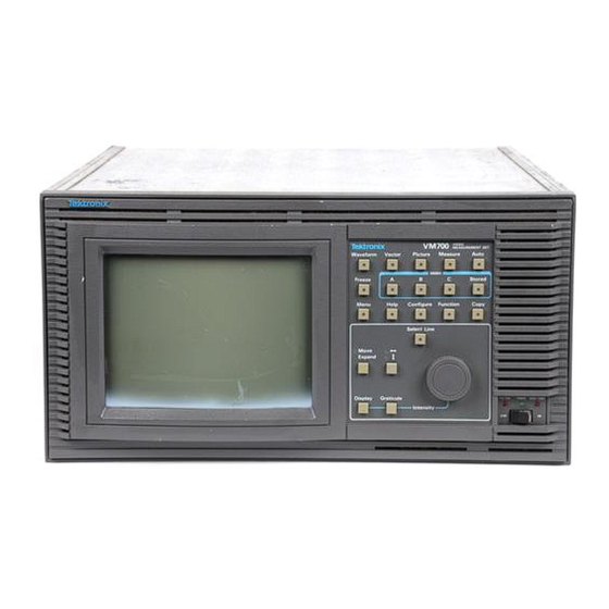
Tektronix VM700 Manuals
Manuals and User Guides for Tektronix VM700. We have
1
Tektronix VM700 manual available for free PDF download: Service Manual
Tektronix VM700 Service Manual (355 pages)
Video Measurement Set
Brand:
Tektronix
| Category:
Measuring Instruments
| Size: 6 MB
Table of Contents
Service Manual
3
Table of Contents
3
List of Tables
13
General Safety Summary
17
Service Safety Summary
19
Contents of the Manual
20
Preface
20
Electrical Characteristics
21
Specification
21
Table 1- 1: Input Characteristics
21
Table 1- 2: Digitizer
22
Table 1- 3: Synchronization
23
Environmental
24
Physical Characteristics
24
Power Requirements
24
Table 1- 4: Physical Characteristics
24
Table 1- 6: Environmental Specification
24
Table 1- 7: Certifications and Compliances
26
Table 1- 8: Safety Standards
27
Table 1- 9: Safety Certification Compliance
27
Table 1- 10: Rear Panel Signal Connectors
28
Table 1- 11: Optional Power Cords
29
Power Line Conditioner for Option A1 and A2 Power Cords
30
Table 1- 12: AC Electrical Characteristics
30
Measure Mode
32
PAL Measurement Specifications
32
Table 1- 15: Bar Line Time
32
Table 1- 16: Bounce
32
Table 1- 17: Burst Frequency
33
Table 1- 18: Chrominance to Luminance
33
Table 1- 19: Chrominance Noise
33
Table 1- 20: Chrominance Nonlinearity
33
Table 1- 21: Color Bar
33
Table 1- 22: Differential Gain and Phase
34
Table 1- 23: Frequency Response and Group Delay
34
Table 1- 24: Horizontal Blanking
34
Table 1- 25: Horizontal Timing
34
Table 1- 26: Incidental Carrier Phase Modulation
35
Table 1- 27: Jitter
35
Table 1- 28: K-Factor
35
Table 1- 29: Level Meter
35
Table 1- 30: Line Frequency
35
Table 1- 31: Luminance Nonlinearity
35
Table 1- 32: Multiburst
36
Table 1- 33: Noise Spectrum
36
Table 1- 34: SCH Phase
36
Table 1- 35: Two Field
36
Table 1- 36: Vertical Blanking
36
Auto Mode
37
Table 1- -37: VITS
37
Measure Mode
41
NTSC Measurement Specifications
41
Auto Mode
46
Audio Option 40, Option 41, and Option 42 Specifications
51
Automatic Audio Test Specifications
51
Audio Analyzer Specifications
52
Audio Spectrum Specifications
54
Multitone Analyzer Specifications
55
A/V Timing Specifications (Option 42)
56
Option 48 GPIB Specification
56
Table 1- -5: Power Requirements
57
Option 1S SDI Specification
58
Installation
65
Operating Information
65
Power Requirements
65
Unpackaging
65
Changing Line Voltage Range and Fuse
66
Power Cord
66
Figure 2- 1: Power Line Conditioner with a Rackmounted VM700T
67
Installing the Power Line Conditioner
67
Calibrating the Touch Screen
68
Power on Diagnostics
68
Figure 2- 2: VM700T Startup Menu
69
Figure 2- 3: Touch Screen Calibration (Display)
70
Figure 2- 6: Diagnostic Configuration Menu
71
Setting the Power on Mode
71
Figure 2- 7: Set Diagnostics Power up Mode Menu
72
Measurement Set Operating Modes
72
Waveform Mode
72
Auto Mode
73
Measure Mode
73
Picture Mode
73
Vector Mode
73
Hardcopy
74
Remote Operation
74
User-Programmable Functions
74
VM700T Video Measurement Set Service Manual
74
Figure 2- 8: the VM700T Video Measurement Set Front Panel
75
Front Panel Controls
75
Touch Screen
75
Figure 2- 9: Measurement Set Keypad
76
Keypad
76
Bandwidth
79
Connecting Inputs and Outputs
79
Control Knob
79
Equipment/Signal Sources Required
79
Figure 2- 10: VM700T Video Measurement Set Rear Panel
80
Rear Panel and Connections
80
Equipment/Video Signal Sources Required
82
Figure 2- 11: Video Signal Input Connectors
82
Connecting Audio Option 40 to a Source
83
Figure 2- 12: Cables and Connectors Supplied with Audio Option 40
83
Figure 2- 13: Option 40 Connectors and Pin Assignments
83
Input Connector Pin Assignments
83
Connecting Audio Option 41 to a Source
84
Option 41 Audio Signal Interconnection Cable
84
Figure 2- 15: GPIB Board Rear Panel
85
GPIB Indicator LED
85
GPIB Option 48 Signal Connections and Rear Panel
85
SDI Option 1S Rear Panel Connections
86
Figure 2- 16: VM700T Rear Panel with Option 1S Installed
87
Figure 2- 17: Option 1S Rear Panel
87
Overview of the VM700T System
89
Theory of Operation
89
Analog Input Board (A1)
91
Channel Selection
91
Clamp and Bias Generator
91
Clamped Input Amplifiers
91
Loop-Through Inputs
91
Mode Control
91
Module Functional Description
91
Figure 3- 1: Analog Input Board (A1) Block Diagram
92
Calibration DAC
93
Differential Amplifier
93
Dither Generator and Dither Amplifier
93
Dynamic Offset Generator and Offset Amplifier
93
Variable-Gain Amplifier
93
DVM Selection and DVM
94
Sync Selection
94
The Genlock Board (A2)
95
Figure 3- 2: Genlock Board (A2) Block Diagram
96
Sync Stripper
96
FH Generator
97
Frame Decoder
97
Frame Rate Synthesizer
97
Phase-Locked Loop (PLL)
97
Stripped Sync Processing
97
Control
98
Output Generator
98
Status
98
Figure 3- 3: ADC Board Block Diagram
100
Overrange Detector
101
Sample Clock
101
Filter Switch Board (A4)
102
Figure 3- 4: Filter Switch Board (A4) Block Diagram
103
Filter Select and Control
103
CPU Board (A5)
104
Figure 3- 5: CPU Board Block Diagram
104
System Bus
104
Display ASIC and VRAM
105
Dram
105
Eprom
105
Flash EPROM
105
Nvram
105
Nvram Simm
105
Real-Time Clock
105
Connector
106
CPU I/O Board (A20)
106
Figure 3- 6: CPU I/O Board Block Diagram
106
Front Panel Processor
106
Parallel Port Interface
106
Serial Ports
106
Data Acquisition/Controller Board (A18)
108
Fifo/Demultiplexor
108
Acquisition Clock
109
Acquisition Control
109
Data Bus Interface
109
Figure 3- 7: Acquisition Circuitry Block Diagram
109
Bus Buffers
110
Controller Section
110
Clamp Counters
111
Controller ASIC
111
Figure 3- 8: Controller Section Block Diagram
111
Output Latches and Analog Input Board Interface
111
Data and Address Latches Onto the BCD0-12 Bus
112
ECL-To-TTL Conversion
112
Sequencer (State Machine)
112
Status Counter
112
Trigger RAM
112
Dynamic Settings
113
Figure 3- 9: Dither Generator 64-Step Dither Waveform
114
Figure 3- 10: Front Panel Board Block Diagram
115
Front Panel Board (A10A1)
115
Control Knob
116
Figure 3- 11: Keypad Board (A10A2) Block Diagram
116
Keypad Board (A10A2)
116
Leds
116
Push Buttons
116
+12 V and + 5 V Supplies
117
Main Interconnect Board (Left and Right) (A11)
117
Picture Monitor (A14)
117
Vertical Deflection
117
Video Amplifier
117
Figure 3- 12: Picture Monitor Simplified Block Diagram
118
Horizontal Deflection
118
High Voltage
119
Housekeeping Power Supply
119
Input Power Rectifier
119
Inverter Switching Circuit
119
Power Supply (A15)
119
Trace Rotation
119
+12 V and 15 V Regulators
120
Figure 3- 13: Simplified Block Diagram of the Power Supply
120
Alarm Logic
121
Alarm Sensing
121
Audio Processor Board (A12)
121
Fan Drive
121
Option 40 Audio Measurements
121
Address Buffers
122
Address Decoders
122
Audio Processor Interface
122
Bus Buffers
122
Figure 3- 14: Audio Processor Block Diagram
122
Communication Ports
123
Data Buffers
123
DSP Processor and I/O Interface
123
Interrupt Generator
123
Interrupt Generator/Status Port
123
Oscillator
123
Reset Register
123
Audio Data Register
124
Control Lines
124
CPU Access Disable
124
P Memory
124
Program Loading
124
Static RAM
124
Audio Analog Board (A13)
125
Input Amplifier
125
Input Amplifiers
125
Signal Input
125
Stepped Attenuator
125
Figure 3- 15: Audio Analog Block Diagram
126
400 Hz Notch Filter/Dac Output
127
DAC Output
127
Notch Filter Operation
127
Audio Board Control
128
CH 2 (and CH 1) Amplifier
128
Input Clamp
128
Option 40 A/D Converter
128
Opto-Isolators
128
Control Register
129
Counter/Decoder
129
Balanced Input Selector
130
Calibration DAC
130
Floating Power Supply
130
Option 41 Audio Analog Board
130
Figure 3- 16: Audio Analog Block Diagram
131
Figure 3- 17: GPIB Board Location in the Measurement Set
132
Option 48 GPIB Interface Board (A19)
132
Figure 3- 18: Block Diagram of the GPIB Interface Option Board
133
Figure 3- 19: GPIB Rear Panel Arrangement
134
Option 1S Serial Digital Measurements
135
SDI Board
135
SDI Rear Panel Interface Assembly
135
Figure 3- 20: Option 1S Block Diagram
136
Performance Verification
139
Self Diagnostics
139
Test Equipment Required
144
System Verification Procedures
145
Audio Option Verification Procedure
151
Test Equipment Required
151
Audio Option 40 Verification Procedure
153
Check Level Measurement Accuracy and Flatness
153
Option 40 Level Accuracy and Flatness
153
Specifications Checked
153
Check Distortion and Distortion Measurement Accuracy
155
Option 40 Distortion Measurement Accuracy
155
Specification Checked
155
Check Frequency and Phase Measurement Accuracy
156
Option 40 Frequency Accuracy and Channel Phase Difference
156
Specifications Checked
156
Audio Option 41 Triple-Input Verification Procedure
157
Configuring Source Selection Audio
157
Check Level Measurement Accuracy and Flatness
158
Option 41 Level Accuracy and Flatness
158
Check Distortion and Distortion Measurement Accuracy
160
Option 41 Distortion Measurement Accuracy
160
Check Frequency and Phase Measurement Accuracy
161
Option 41 Frequency Accuracy and Channel Phase Difference
161
SDI Option 1S Performance Verification
163
Preliminary Setup
164
SDI Analog Ref Input
165
Eye Diagram Application
166
Jitter Application
168
Interchannel Timing Application
172
SDI Output
173
VM700T Video Measurement Set Service Manual
184
Figure 2- -4: Touch Screen Calibration (Panel)
187
Figure 2- -5: Panel Calibration Values
187
VM700T Video Measurement Set Service Manual
194
Advertisement
Advertisement
Related Products
Tektronix VM700T
Tektronix VM700A VMTB
Tektronix VM5000 Series
Tektronix VM Series
Tektronix VM700A VMTX
Tektronix VM5000HD
Tektronix VX4802
Tektronix IntelliFrame VX1420A
Tektronix VX1411
Tektronix VX4286
Tektronix Categories
Test Equipment
Measuring Instruments
Amplifier
Portable Generator
Printer
More Tektronix Manuals
Login
Sign In
OR
Sign in with Facebook
Sign in with Google
Upload manual
Upload from disk
Upload from URL