Tektronix VX1411A IntelliFrame VXIbus Mainframe Manuals
Manuals and User Guides for Tektronix VX1411A IntelliFrame VXIbus Mainframe. We have 2 Tektronix VX1411A IntelliFrame VXIbus Mainframe manuals available for free PDF download: Instruction Manual
Advertisement
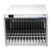
Tektronix VX1411A IntelliFrame VXIbus Mainframe Instruction Manual (130 pages)
VXIbus Mainframe