Tektronix VM700T Service Manual
Video measurement set
Hide thumbs
Also See for VM700T:
- Programmer's manual (277 pages) ,
- User manual (207 pages) ,
- Instructions manual (58 pages)
Table of Contents
Advertisement
Quick Links
Advertisement
Chapters
Table of Contents
Troubleshooting

Related Manuals for Tektronix VM700T


Summary of Contents for Tektronix VM700T
- Page 1 Service Manual VM700T Video Measurement Set 070-9630-05 Warning The servicing instructions are for use by qualified personnel only. To avoid personal injury, do not perform any servicing unless you are qualified to do so. Refer to all safety summaries prior to performing service.
- Page 2 Copyright © Tektronix, Inc. All rights reserved. Tektronix products are covered by U.S. and foreign patents, issued and pending. Information in this publication supercedes that in all previously published material. Specifications and price change privileges reserved. Tektronix, Inc., P.O. Box 500, Beaverton, OR 97077 TEKTRONIX and TEK are registered trademarks of Tektronix, Inc.
- Page 3 WARRANTY Tektronix warrants that the products that it manufactures and sells will be free from defects in materials and workmanship for a period of one (1) year from the date of shipment. If a product proves defective during this warranty period, Tektronix, at its option, either will repair the defective product without charge for parts and labor, or will provide a replacement in exchange for the defective product.
-
Page 5: Table Of Contents
..........2- - 10 VM700T Video Measurement Set Service Manual... - Page 6 ............3- - 10 VM700T Video Measurement Set Service Manual...
- Page 7 ........3- - 27 VM700T Video Measurement Set Service Manual...
- Page 8 ..........3- - 40 VM700T Video Measurement Set Service Manual...
- Page 9 ........... . . 4- - 35 VM700T Video Measurement Set Service Manual...
- Page 10 Using the Replaceable Mechanical Parts List ......10- - 1 VM700T Video Measurement Set Service Manual...
- Page 11 Table of Contents List of Figures Figure 2- -1: Power line conditioner with a rackmounted VM700T 2- -3 Figure 2- -2: VM700T Startup menu ......
- Page 12 Table of Contents Figure 4- -1: VM700T Startup Menu ......4- -1 Figure 4- -2: Instrument run modes menu .
- Page 13 Figure 6- -29: Mounting stationary rack sections ....6- -47 Figure 6- -30: Installing and removing the VM700T from the rack 6- -48 Figure 6- -31: VM700T diagnostics menus overview .
- Page 14 ......... 6- -105 Figure 9- -1: VM700T Video Measurement Set simplified block diagram .
- Page 15 ........1- -17 VM700T Video Measurement Set Service Manual...
- Page 16 ....1- -27 Table 1- -75: FCC horizontal blanking interval timing ... 1- -27 VM700T Video Measurement Set Service Manual...
- Page 17 ......1- -44 Table 1- -110: Environmental specification ..... 1- -44 xiii VM700T Video Measurement Set Service Manual...
- Page 18 ....... . . 2- -21 Table 3- -1: Signals used by VM700T RS-232C ports ... .
-
Page 19: General Safety Summary
Do Not Operate in Wet/Damp Conditions. Do Not Operate in an Explosive Atmosphere. Keep Product Surfaces Clean and Dry. Provide Proper Ventilation. Refer to the manual’s installation instructions for details on installing the product so it has proper ventilation. VM700T Video Measurement Set Service Manual... - Page 20 CAUTION indicates a hazard to property including the product. Symbols on the Product. The following symbols may appear on the product: WARNING Protective Ground CAUTION Double High Voltage (Earth) Terminal Refer to Manual Insulated VM700T Video Measurement Set Service Manual...
-
Page 21: Service Safety Summary
To avoid electric shock, do not touch exposed connections. X-Radiation. To avoid x-radiation exposure, do not modify or otherwise alter the high-voltage circuitry or the CRT enclosure. X-ray emissions generated within this product have been sufficiently shielded. xvii VM700T Video Measurement Set Service Manual... - Page 22 Service Safety Summary xviii VM700T Video Measurement Set Service Manual...
-
Page 23: Preface
Preface This is a service manual for the VM700T Video Measurement Set. It is a module-level repair manual for use by a qualified service person in the isolation of faulty modules and repair by module exchange. Contents of the Manual This manual contains the following sections: 1. -
Page 24: Contacting Tektronix
This phone number is toll free in North America. After office hours, please leave a voice mail message. Outside North America, contact a Tektronix sales office or distributor; see the Tektronix web site for a list of offices. VM700T Video Measurement Set Service Manual... -
Page 25: Specification
75 Ω in use or not; power on or off. Input Signal Range +3, –6 dB with respect to 1 V nominal video (1.41 V to 0.5 V ) terminated in 75 Ω. Coupling DC, AC, Clamp 1- 1 VM700T Video Measurement Set Service Manual... -
Page 26: Table 1- 2: Digitizer
- - 60 dBfs typical; with 5 MHz, - - 50 dBfs RMS, input Anti-aliasing filter attenuation At 7.16 MHz (NTSC) 35 dB or greater At 8.86 MHz (PAL) 40 dB or greater 1- 2 VM700T Video Measurement Set Service Manual... -
Page 27: Table 1- 3: Synchronization
+12 dB with respect to 286 mV nominal sync amplitude External Minimum - - 8 dB with respect to 286 mV nominal sync Composite sync amplitude Maximum 8 V peak-to-peak Composite sync 1- 3 VM700T Video Measurement Set Service Manual... -
Page 28: Physical Characteristics
Performance requirement Temperature ° ° Operating C to +50 ° ° Nonoperating - - 55 C to +75 Altitude Nonoperating To 50,000 feet (15240 meters) Operating To 15,000 feet (4572 meters) Sine Vibration 1- 4 VM700T Video Measurement Set Service Manual... - Page 29 Transportation Qualified under NTSB Test Procedure 1A, Category II (30 inch drop) Humidity ° Operating Up to 95% at or below 50 ° Nonoperating Up to 95% at or below 60 1- 5 VM700T Video Measurement Set Service Manual...
-
Page 30: Table 1- 7: Certifications And Compliances
High-quality cables have a reliable, continuous outer shield (braid and foil) that has low impedance connections to shielded connector housings at both ends. Peak Inrush Current: 35.5 A @ 230 VAC, 50 Hz. VM700T with Power Line Conditioner accessory used on 230 Vac power mains. 1- 6 VM700T Video Measurement Set Service Manual... -
Page 31: Table 1- 8: Safety Standards
Pollution Degree Pollution Degree 2 (as defined in IEC 1010-1). Do not operate in environments where conductive pollutants may be present. Note - - Rated for indoor use only 1- 7 VM700T Video Measurement Set Service Manual... -
Page 32: Table 1- 10: Rear Panel Signal Connectors
GRLY 1 closes the relay set GRLY 0 opens the relay BNC. 75 Ω Termination required when not used as feed-through signal path. CH A, CH B, CHC, and Ext Sync Feed-Through Connectors 1- 8 VM700T Video Measurement Set Service Manual... -
Page 33: Table 1- 11: Optional Power Cords
230 V European and United Kingdom power cord options A1 and A2 also require the VM700T power line conditioning box for operation in EU countries. The power line conditioner prevents power spikes from the VM700T power supply from entering the commercial power mains. -
Page 34: Power Line Conditioner For Option A1 And A2 Power Cords
161-0066-09 Euro 161-0066-10 U.K. See the VM700T Power Requirements in Table 1- 5 for the operating voltage range of the VM700T without the Power Line Conditioner box inline. Use the part numbers listed above to order a new power cord for use with the VM700T Power Line Conditioner box. - Page 35 Tektronix Class 5 Shock Test 16 drops, 4 axes, 30 Grms @ 11mS half-sine wave See the VM700T Environmental Characteristics in Table 1- 6 for the operating temperature range of the VM700T operating without the Power Line Conditioner box inline.
-
Page 36: Pal Measurement Specifications
0 to 20% ±100 ns Bar Width 10 s to 30 s Table 1- 16: Bounce Measurement Range Accuracy ±1% Peak Deviation 0 to 50% ±100 msec Settling Time 0 to 10 sec 1- 12 VM700T Video Measurement Set Service Manual... -
Page 37: Table 1- 17: Burst Frequency
Absolute mode accuracy Relative mode accuracy ±3.5 mV ±0.2% Luminance Level 0 to 700 mV ±1.0% of nominal ±0.2% Chrominance Level (excluding gray and 0 to 700 mV black) ±180° ±0.5° ±0.1° Chrominance Phase 1- 13 VM700T Video Measurement Set Service Manual... -
Page 38: Table 1- 22: Differential Gain And Phase
1 s to 8 s ±25 ns Burst Width 1.4 s to 3 s ±25 ns Sync to Burst Start 5 s to 8 s ±0.5% Sync Level 75 mV to 600 mV 1- 14 VM700T Video Measurement Set Service Manual... -
Page 39: Table 1- 26: Incidental Carrier Phase Modulation
Table 1- 30: Line Frequency Measurement Range Accuracy ±3% ±0.1% Line Frequency ±3% ±0.1% Field Frequency Table 1- 31: Luminance Nonlinearity Measurement Range Absolute mode accuracy Relative mode accuracy ±0.4% ±0.2% Luminance NonLinearity 0 to 100% 1- 15 VM700T Video Measurement Set Service Manual... -
Page 40: Table 1- 32: Multiburst
80 ns to 1 s ±10 ns Broad Pulse Width 80 ns to 1 s Vertical Blanking Field 1 19 lines to 30 lines Vertical Blanking Field 2 19 lines to 30 lines 1- 16 VM700T Video Measurement Set Service Manual... -
Page 41: Auto Mode
Table 1- 39: Field Blanking timing measurements Measurement Range Accuracy ±10 ns Equalizing Pulse Duration 1.4 s to 20 s (2.35 s nominal) ±10 ns Broad Pulse Separation 1.4 s to 20 s (4.7 s nominal) 1- 17 VM700T Video Measurement Set Service Manual... - Page 42 CCIR Rec. 569 ±50% ±1% C/L Gn Err (using modulated Pulse) ±2.1 mV Sync Amplitude 75 mV to 600 mV ±3 mV Burst Amplitude 75 mV to 600 mV ±2% Burst Amplitude Difference 1- 18 VM700T Video Measurement Set Service Manual...
- Page 43 Field Time Distortion 0 to 35% Field Square Wave ±50% ±0.2% Chrominance-Luminance G1 or G2 CCIR Rec. 569 Intermodulation (0% nominal) ±0.4% Luminance Non-linear 0 to 50% CCIR Rec. 569 Distortion (0% nominal) 1- 19 VM700T Video Measurement Set Service Manual...
- Page 44 61 dB to 70 dB Table 1- 46: Incidental Carrier Phase Modulation Measurement Range Accuracy ±1.0° ICPM (requires Zero-Carrier Pulse and the quadrature output of the 0 to 30° demodulator on Channel C) 1- 20 VM700T Video Measurement Set Service Manual...
-
Page 45: Ntsc Measurement Specifications
Accuracy ±1% Peak Deviation 0 to 50% ±100 msec Settling Time 0 to 10 sec Table 1- 49: Burst Frequency Measurement Range Relative mode accuracy ±100 Hz ±0.5 Hz Burst Frequency Error 1- 21 VM700T Video Measurement Set Service Manual... - Page 46 ±180° of nominal ±0.5° of nominal ±0.1° Chrominance Phase Table 1- 55: SMPTE color bar nominal values Color LUM (mV) Chroma P–P (mV) Phase (degrees) Yellow 494.6 444.2 167.1 Cyan 400.4 630.1 283.4 1- 22 VM700T Video Measurement Set Service Manual...
- Page 47 Sync to Burst Start (RS–170A) 4 s to 10 s ±25 ns Sync to Burst End (FCC) 4 s to 10 s ±10 ns (FCC) Front Porch 0.1 s to 3.5 s ±10 ns (RS–170A) 1- 23 VM700T Video Measurement Set Service Manual...
- Page 48 Table 1- 63: Level Meter Measurement Range Absolute mode accuracy ±3.5 mV Level Meter 0 to 1.4 V Table 1- 64: Line Frequency Measurement Range Absolute mode accuracy ±3% ±0.1% Line Frequency ±3% ±0.1% Field Frequency 1- 24 VM700T Video Measurement Set Service Manual...
- Page 49 Table 1- 69: Short Time Distortion Measurement Range Absolute mode accuracy ±5% SD Short-Time Distortion 0 to 25% SD Table 1- 70: Two Field Measurement Range Absolute mode accuracy ±0.5% Field Time Distortion 0 to 40% 1- 25 VM700T Video Measurement Set Service Manual...
-
Page 50: Auto Mode
Horizontal Blanking ±20 ns Sync to Setup 5 s to 18 s Horizontal Blanking ±140 ns Sync to Start of Burst 4 s to 8 s Horizontal Blanking (0.5 cycles) ±20 ns 1- 26 VM700T Video Measurement Set Service Manual... - Page 51 ±5 ns Chrominance to Luminance FCC/NTC–7 Composite Delay (Relative Chroma Time) ±1% Chrominance to Luminance 0 to 160% FCC/NTC–7 Composite Gain (Relative Chroma Level) ±0.3% Differential Gain 0 to 100% FCC/NTC–7 Composite 1- 27 VM700T Video Measurement Set Service Manual...
- Page 52 Table 1- 79: Incidental Carrier Phase Modulation Measurement Range Accuracy Measurement specifications ±1.0° ICPM (requires Zero Carrier Pulse and the 0 to 30° FCC or NTC–7 Composite quadrature output of the demodulator on channel C) 1- 28 VM700T Video Measurement Set Service Manual...
- Page 53 ±1 IRE when tude (0 to 80% of Bar when burst is not used and 0 IRE burst and bar are not used) to 80 IRE when burst and bar are not used) 1- 29 VM700T Video Measurement Set Service Manual...
- Page 54 26 dB to 60 dB Quiet Line ±2.0 dB 61 dB to 70 dB ±1.0 dB Periodic SNR 26 dB to 60 dB Quiet Line ±2.0 dB 61 dB to 70 dB 1- 30 VM700T Video Measurement Set Service Manual...
-
Page 55: Audio Option 40, Option 41, And Option 42 Specifications
The value for other test levels can be calculated from the formula (- 60 - Test Level). Measured with Quasi- Peak response as per CCIR 468-4 recommendation. The measurement range can be determined from the formula (70 + Test Level). Weighting filter as per CCIR 468-4 recommendation. 1- 31 VM700T Video Measurement Set Service Manual... -
Page 56: Audio Analyzer Specifications
The weighting filter is a 15 kHz sharp-cutoff, low-pass filter. Audio Analyzer Specifications Table 1- 87: Frequency and Noise specifications Measurement Specification Comments Level Maximum Allowable Input +30 dBu (24.5 V rms) 1- 32 VM700T Video Measurement Set Service Manual... - Page 57 - - 50 dBu to - - 60 dBu ± 1.0 dB ± 0.1 dB - - 60 dBu to - - 70 dBu Level differences between channels is 0.2 dB at levels of - 50 dBu and greater. 1- 33 VM700T Video Measurement Set Service Manual...
-
Page 58: Audio Spectrum Specifications
Harmonics up to the 20 kHz measurement bandwidth are displayed. Measurement Update Rate 6 readings per second ± 24 Hz View Harmonic Measurement Window All signal energy within the view window is measured. 1- 34 VM700T Video Measurement Set Service Manual... -
Page 59: Multitone Analyzer Specifications
Multitone 3 - - 13.8 dB Multitone 4 - - 15.9 dB Reference Frequency for Multitone Recognition Multitone 1 422 Hz Multitone 2 562 Hz Multitone 3 656 Hz Multitone 4 750 Hz 1- 35 VM700T Video Measurement Set Service Manual... -
Page 60: A/V Timing Specifications (Option 42)
Timing Range ±1 ms Timing Accuracy Option 48 GPIB Specification The GPIB interface function set implemented in the VM700T GPIB interface and the capability level is given in Table 1- - 95. 1- 36 VM700T Video Measurement Set Service Manual... - Page 61 Specification Table 1- 95: IEEE 488.1 interface functions implemented in the VM700T GPIB interface card Function Implemented Notes Source Handshake Complete capability Acceptor Handshake Complete capability Talker Basic Talker, Serial Poll, Unaddr if MLA Talker (extended) No capability Listener Basic Listener, Unaddr if MTA...
-
Page 62: Option 1S Sdi Specification
Tektronix Product No. S3FG100 Option 1S SDI Specification The specifications for Option 1S are the same as those listed for the VM700T Video Measurement Set except where listed below. The following specifications are only valid when Option 1S is installed in a VM700T. - Page 63 Max jitter (ns) = 1200÷jitter frequency (kHz) for frequencies below 1.33 MHz Frequency Response of Jitter- Waveform and Spectrum displays 143 Mb/s 3 dB to 0.5 MHz; +3 dB to - - 5 dB at 3 MHz 1- 39 VM700T Video Measurement Set Service Manual...
- Page 64 40 ppm/s Drift Rate Accuracy 5 ppb/s Table 1- 102: SDI Interchannel Timing application Characteristic Performance requirement Supplemental information Digital-to-Digital Accuracy 1 sample Range 0.5 frame Digital-to-Analog Accuracy 400 ns Range 0.5 frame 1- 40 VM700T Video Measurement Set Service Manual...
- Page 65 Table 1- 103: SDI Audio/Video Timing application Characteristic Performance requirement Supplemental information Embedded Signal Accuracy 200 s Range 2 seconds; less range on data streams heavily loaded with ancillary data External Signal Accuracy 200 s Range 2 seconds 1- 41 VM700T Video Measurement Set Service Manual...
- Page 66 Max jitter (ns) = 130÷jitter frequency (kHz) for frequencies below 160 kHz Cable Length Maximum for No Equivalent to 200 meters of Belden Equivalent to 250 meters of Belden 8281 cable typical Bit Errors 8281 cable 1- 42 VM700T Video Measurement Set Service Manual...
- Page 67 Belden 8281 cable Table 1- 106: LTC Input Characteristic Performance requirement Supplemental information Electrical Characteristics Input type Miniature XLR >10 kΩ Input Impedance Signal Characteristics Format Longitudinal Time Code per IEC pub. 461 1- 43 VM700T Video Measurement Set Service Manual...
- Page 68 2 V Format AES/EBU digital-audio per AES3-1992 (ANSI S4.40- - 1992) Table 1- 110: Environmental specification Characteristic Performance requirement Supplemental information Maximum operating temperature 45_ C VM700T with Option 1S installed 1- 44 VM700T Video Measurement Set Service Manual...
-
Page 69: Operating Information
RS-232C ports on the rear panel. Installation The standard measurement set is a rack mounted unit. Refer to the VM700T Rack Mounting Instructions on page 6- -44 for the rack mounting installation instruc- tions. The following unpacking and power requirements information is repeated there. -
Page 70: Changing Line Voltage Range And Fuse
European power cord options A1 and A2 require an additional accessory for operation in the EU countries. When the VM700T Video Measurement Set is ordered with either the A1 or the A2 power cord option, the VM700T Power Line Conditioning accessory is also provided. -
Page 71: Installing The Power Line Conditioner
(see Figure 2- -1). NOTE. Do not mount the power line conditioning box in any location that blocks the air flow (in or out) of the VM700T or any other product installed in the rack. VM700T... -
Page 72: Power On Diagnostics
Operating Information Benchtop Mounting. For a standalone VM700T on a benchtop or for portable use, apply the four adhesive rubber feet provided with the accessory to the bottom of the box at the corners. Place the conditioner box in a convenient location where you can make the power cord connections. -
Page 73: Calibrating The Touch Screen
Figure 2- 2: VM700T Startup menu 3. Use the large control knob to highlight the T in the Calibrate Touch Panel Interface line of the VM700T startup menu. Press the Select Line button to make the selection to calibrate. 4. The first touch screen calibration instructions are then displayed as shown in Figure 2- -3. -
Page 74: Figure 2- 3: Touch Screen Calibration (Display)
Figure 2- 3: Touch screen calibration (display) 5. After making the adjustment requested and storing the current setting, the VM700T displays a second set of instructions as shown in Figure 2- -4. Follow the directions given in the screen. --- TOUCH PANEL INTERFACE CAL (PANEL) --- (press ‘AUTO’... -
Page 75: Setting The Power On Mode
1. Press and hold the Menu button while turning on the power to display the VM700T Startup menu (shown in Figure 2- -2 on page 2- -5). In the startup menu, highlight the C in the Diagnostic Configuration line and press the Select Line button. -
Page 76: Measurement Set Operating Modes
Your selection is stored in the diagnostics NVRAM. 4. Turn the VM700T off and back on again to restart normal operation. Low Level Diagnostic Interface (knob moves cursor, “Select Line” inputs selection) --- SET DIAGNOSTICS POWERUP MODE --- Select a Powerup Mode from the list below. -
Page 77: Vector Mode
Mode from one of these locations: the Configuration menu (two locations), the Measure menu, or through remote control. NOTE. To access any of the functions of Option 1S, you must set the VM700T to Digital Mode. To access any of the analog measurement applications of the VM700T, you must set the VM700T to Analog Mode. -
Page 78: User-Programmable Functions
Measure menu will be only those relevant to the selected signal source type (analog or digital). When the VM700T is set to Digital Mode, the Auto mode button provides direct access to the SDI Format Monitor application. -
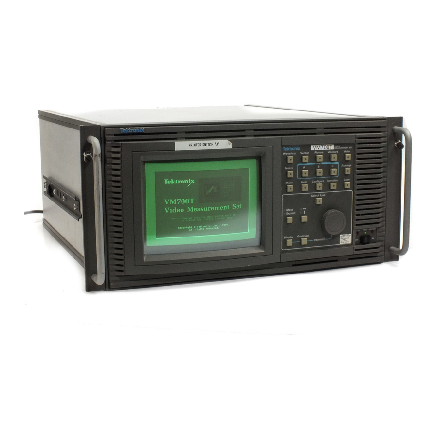
Page 79: Front Panel Controls
The front panel controls (shown in Figure 2- -8) consists of a touch screen interface and a 20-button keypad with a control knob. Figure 2- 8: The VM700T Video Measurement Set front panel Touch Screen The display (CRT) area of the measurement set has a touch screen interface for communicating with the measurement set. -
Page 80: Keypad
You can get measurement results reported in either mode. Parameters such as clamping, sync source, and the displayed line (system line) are common for all the manual modes of operation. 2- 12 VM700T Video Measurement Set Service Manual... - Page 81 H Menu Button. The Menu button displays a menu of soft keys across the bottom of the touch screen. In some cases, touching a soft key displays a further submenu of soft keys. 2- 13 VM700T Video Measurement Set Service Manual...
-
Page 82: Control Knob
Configu- ration menu. For a full description of the Configure button and the menus accessed, refer to the VM700T Option 01 (NTSC) and Option 11 (PAL) User Manual. H Function Button. The Function button accesses user-created functions and the selection choices for running them. -
Page 83: Equipment/Signal Sources Required
VGA monitor. Certain options, such as Camera and Component, require connections to specific inputs for correct operation. Refer to the appropriate option user manual when connecting signals to make those option measure- ments. 2- 15 VM700T Video Measurement Set Service Manual... -
Page 84: Rear Panel And Connections
RS-232 ports Figure 2- 10: VM700T Video Measurement Set rear panel The following paragraphs briefly describe each of the rear panel features. H Line Voltage and Switching Module. The module includes the connector and filter for line input voltage, the line fuse, and the main power switch. - Page 85 The RS 232 ports also enables you to access the measurement set remotely using a terminal or a PC. Refer to the VM700T RS-232 Interface Programmer Manual for information on configuring the measurement set for remote access and the remote control commands.
-
Page 86: Equipment/Video Signal Sources Required
External Sync inputs (see Figure 2- -11). Non-loop through signals must have the signal output terminated with precision 75 Ω termination, three of which are provided as standard accessories to the VM700T Video Measurement Set. You must use an appropriate test signal to test the measurements. You can obtain the test signals needed from an appropriate test signal generator. -
Page 87: Connecting Audio Option 40 To A Source
Operating Information Connecting Audio Option 40 to a Source The VM700T Audio option comes with two male mini-XLR to female XLR adapter cables wired as shown in Figure 2- -12. The mini-XLR ends of these cables connect the Audio option input to an appropriate audio signal source. -
Page 88: Connecting Audio Option 41 To A Source
Input 3 Input 2 Input 1 (right) (right) (right) Male DB-37 Input 3 Input 2 Input 1 (left) (left) (left) Figure 2- 14: Option 41 (Triple-Input Audio) input connector pin locations 2- 20 VM700T Video Measurement Set Service Manual... -
Page 89: Gpib Option 48 Signal Connections And Rear Panel
Service request (SRQ) pending when on Yellow Remote control active when on LOCK Front Panel lockout CACT Green Controller active state when on SCTL Green System control (never on) Figure 2- 15: GPIB board rear panel 2- 21 VM700T Video Measurement Set Service Manual... -
Page 90: Sdi Option 1S Rear Panel Connections
Operating Information SDI Option 1S Rear Panel Connections Figure 2- -16 shows the VM700T rear panel with Option 1S installed. Figure 2- -17 shows a close-up of the Option 1S rear panel. The Option 1S rear-panel connectors provide the following functions: H The SDI Ch. -
Page 91: Figure 2- 16: Vm700T Rear Panel With Option 1S Installed
Fuse ON/OFF Line voltage Parallel Alarm RS-232 connector switch selector output printer port connector ports Figure 2- 16: VM700T rear panel with Option 1S installed Figure 2- 17: Option 1S rear panel 2- 23 VM700T Video Measurement Set Service Manual... - Page 92 Operating Information 2- 24 VM700T Video Measurement Set Service Manual...
-
Page 93: Theory Of Operation
Overview of The VM700T System The video signal enters the VM700T analog input board (A1) through one of three high-impedance loop-through connectors (see the overall block diagram in the diagrams sections of this manual). After it buffers and clamps the input signal and selects a channel, the A1 board passes the signal to the A4 filter switch board where analog filtering (signal conditioning) occurs. - Page 94 Flash EPROM, NVRAM, display memory, and display driver hardware. The display driver hardware converts acquired data to video and drives the VM700T display. A monochrome VGA output to the rear panel is also derived from the display driver hardware The Flash EPROM stores application programs and the NVRAM stores system and configuration files created by the user.
-
Page 95: Module Functional Description
Theory of Operation Module Functional Description This part describes the operation of each circuit board module in the VM700T. Block diagrams accompanying the text show the functions of the modules. Analog Input Board (A1) The analog input board performs input selection and applies bias, clamping, offset, gain, and dither to the input video before digital conversion. -
Page 96: Figure 3- 1: Analog Input Board (A1) Block Diagram
A;, B, C, A B, A C, B C, B A, C A,, and C B. Possible channel selection combinations in hardware: A;, B, C, A B, A C, B C, Figure 3- 1: Analog input board (A1) block diagram 3- 4 VM700T Video Measurement Set Service Manual... -
Page 97: Differential Amplifier
A calibration switch on each input channel couples the calibration signal onto the signal path at regular intervals. The output of the ADC provides calibration information that is stored in a look-up table. The VM700T uses the look-up table information to maintain its luminance accuracy specification without the need for periodic readjustments. -
Page 98: Sync Selection
A/B/C button only the video used as the sync source is inverted. DVM Selection and DVM The DVM measures the average picture level (APL). The VM700T measures the analog average as the video exits to the filter switch board. This analog voltage is converted to a frequency output and sent to the acquisition/controller board where it is averaged by a counter. -
Page 99: The Genlock Board (A2)
(ppm) accuracy. It is divided to either an NTSC or PAL line-rate frequency and used as one of the selections for the phase-locked loop reference clock. It is also used as the sampling strobe in 20.25 MHz sampling mode. 3- 7 VM700T Video Measurement Set Service Manual... -
Page 100: Fh Generator
E= 105/125 FH Clock(Sync window) Synthesized Frame Mode Synchronous Mode Rising Edge Line Detect Composite Sync Pulse Decoded Async or Frame Mode 20.25 MHz Mode Figure 3- 2: Genlock board (A2) block diagram 3- 8 VM700T Video Measurement Set Service Manual... -
Page 101: Phase-Locked Loop (Pll)
Impulse noise (such as VCR head switches) is removed by gating composite sync with a 2 microsecond window pulse, centered on the leading edge of sync. 3- 9 VM700T Video Measurement Set Service Manual... -
Page 102: Output Generator
LEDs on the circuit board indicate the current lock status and whether any unlocks have occurred since the last read of the status register. 3- 10 VM700T Video Measurement Set Service Manual... -
Page 103: The Analog-To-Digital (Adc) Board (A3)
The output latch supplies differential drive for the cable transporting the data to the acquisition/controller. The latch is set and reset by ASYNC_SET and ASYNC_RESET from the acquisition/controller board. It is clocked by the OUT_LATCH clock derived from the 4FSC signal. 3- 11 VM700T Video Measurement Set Service Manual... -
Page 104: And - - 2.5 V Regulators
- - LINE OUT LINE AND FRAME - - H PULSE PIPELINE LINE OUT - - FRAME OUT - - V FRAME OUT DELAYS AND OVERRANGE Figure 3- 3: ADC board block diagram 3- 12 VM700T Video Measurement Set Service Manual... -
Page 105: Line And Frame Pulse Pipeline
ADC and the acquisition clocks (CKD and - -CKD) for the acquisition/con- troller board. The clocks to the acquisition system are connected through a 36-pin ribbon cable along with 10-bit data from the A/D converter and the Frame Out and Line Out signals. 3- 13 VM700T Video Measurement Set Service Manual... -
Page 106: Filter Switch Board (A4)
The output amplifier provides the 75 Ω drive needed for the input to the analog Output Amplifier input board. When the acquisition/controller board asserts FIL3 the output amplifier switches from unity gain to a gain of eight. 3- 14 VM700T Video Measurement Set Service Manual... -
Page 107: Filter Select And Control
FILTER SLOT ASSIGNMENTS SLOT 5 1 NTSC BW LIMIT 2 IEEE LOW PASS 3 CHROMA BANDPASS FILTER 4 DIFF STEP 5 LF NOISE Figure 3- 4: Filter switch board (A4) block diagram 3- 15 VM700T Video Measurement Set Service Manual... -
Page 108: Cpu Board (A5)
CPU Board (A5) The CPU and CPU I/O boards are the complete central processing core for the VM700T. The CPU board incorporates Flash EPROM program memory, nonvolatile memory for data and user-programmed routines, the front panel interface, and the display driver hardware. The CPU I/O board provides the interface between two RS232 serial ports, one parallel printer port, and the central processor. -
Page 109: Eprom
A VGA output from the display system permits viewing the display on an external VGA monitor. The VGA connector is located on the back panel of the VM700T 3- 17 VM700T Video Measurement Set Service Manual... -
Page 110: Front Panel Processor
There are two DB9 RS-232 serial communication ports. Of the nine pins in the connector, pins 6 and 9 are not connected. The remaining pins are in the standard configuration for a DB9 RS-232 DTE serial connector as shown in Table 3- -1. 3- 18 VM700T Video Measurement Set Service Manual... -
Page 111: Connector
The VM700T transmits data on this pin. Data) DTR (Data Required for modem connections only. This pin is always high when Terminal the VM700T is turned on. When DTR is asserted, the modem knows Ready) it is connected to a “live” PC/terminal. SG (Signal Ground) DSR (Data Set Unused in the VM700T. -
Page 112: Data Acquisition/Controller Board (A18)
FIFO, as well as latching whether a line or frame pulse or an over-flow or under-flow has occurred. Reading the Min-Max results resets the circuit to begin a new accumulation. 3- 20 VM700T Video Measurement Set Service Manual... -
Page 113: Figure 3- 7: Acquisition Circuitry Block Diagram
HANDSHAKE STATIC RAM ACQUISITION DATA BUS DATA CONTROL IN ADDRESS ADDRESS CONTROL ADDRESS ADDRESS 16 MHZ XTAL SIGNALS TO CLOCK IN CLOCK OUT CONTROL SECTION Figure 3- 7: Acquisition circuitry block diagram 3- 21 VM700T Video Measurement Set Service Manual... -
Page 114: Controller Section
Theory of Operation Controller Section The controller portion of the board performs the following functions: H controls the VM700T analog front end H receives and processes digitized data from the ADC board and passes it to acquisition memory H controls acquisition patterns Figure 3- -8 shows a block diagram for the controller circuitry. -
Page 115: Figure 3- 8: Controller Section Block Diagram
SCLK TO DATA ACQUISITION SECTION CONTROL DYNAMIC ADDRESS SETTINGS OUTPUT BUFFER STATIC RAM LATCHES 2K X 32 ANALOG INPUT CONTROL BOARD DATA INTERFACE BD0-31 BUFFER Figure 3- 8: Controller section block diagram 3- 23 VM700T Video Measurement Set Service Manual... -
Page 116: Status Counter
RAM. Sequencer Address and Data Buffers. When the address buffer is enabled, the sequencer static RAM can be read and written by the microprocessor from the data buffer before starting the sequencer. 3- 24 VM700T Video Measurement Set Service Manual... -
Page 117: Dynamic Settings
Six of the eight bits sent to the dither generator are used as data; the other two are for control. The dither generator’s four control states are the following: H clear H sequence to the next dither level 3- 25 VM700T Video Measurement Set Service Manual... -
Page 118: Figure 3- 9: Dither Generator 64-Step Dither Waveform
Microprocessor access is also a multiplexed operation. A DSACK generator provides the rapid signal generation needed for a minimal number of CPU wait states. This DSACK generator is much faster than the DSACK generator in the interrupt controller. 3- 26 VM700T Video Measurement Set Service Manual... -
Page 119: Front Panel Board (A10A1)
DECODER Keyboard AUTONULL OVERFLOW DETECTOR SYNCHRONOUS INVERTER INTEGRATOR DEMODULATOR CONVERTOR CLK200 To/From Touch MULTIPLEXER Panel Below B050100 To/From Touch Controller Panel B050100 and above Figure 3- 10: Front panel board block diagram 3- 27 VM700T Video Measurement Set Service Manual... -
Page 120: Keypad Board (A10A2)
Theory of Operation Keypad Board (A10A2) The VM700T front-panel push buttons, LED, and the control knob are connected to the keypad board. The keypad board is connected to the front panel board through a flex cable that carries power, the 68008 data bus, enable signals from the front panel board’s address decoder, and two bits of data from the... -
Page 121: Main Interconnect Board (Left And Right) (A11)
Main Interconnect Board. There is a Left and Right board (for the plug in modules on the left and right sides of the VM700T) and an interconnect board that ties the two sides together. -
Page 122: Horizontal Deflection
Width of the display on the CRT is set using the Horizontal Width adjustment. The Horiz Position control adjusts the fine position of the active picture area within the raster-scanned width. 3- 30 VM700T Video Measurement Set Service Manual... -
Page 123: Trace Rotation
+5 V, –5 V, +16.5 V, and –16.5 V. The +16.5 V and –16.5 V are further regulated to produce the +15 V and –15 V supplies to the VM700T and the +12 V display module power. The source voltage for the Fan Drive circuit is also provided by the +12 V supply. -
Page 124: +12 V And 15 V Regulators
Each regulator is a combined operational amplifier and FET current pass element with a feedback loop to the operational amplifier from the output voltage. 3- 32 VM700T Video Measurement Set Service Manual... -
Page 125: Option 40 Audio Measurements
Option 40 Audio Measurements This section describes the operation of the VM700T Video Measurement Set audio option boards. The discussion provides the background information needed for fault isolation to the board level and board replacement; it does not include a component-level description (component-level circuit repair is beyond the scope of this manual). -
Page 126: Audio Processor Interface
The bus buffers are enabled during bus-to-bus accesses. They are disabled to isolate the busses when bus-to-bus accesses are not being done. Address Buffers The address buffers are unidirectional devices that feed the Audio Processor address to the DSP address bus. 3- 34 VM700T Video Measurement Set Service Manual... -
Page 127: Interrupt Generator/Status Port
A second data buffer is a read-only buffer that holds the board version number. Software reads these bits to determine the hardware version installed in the VM700T. Other bits held in the data buffers indicate when a calibration is taking place and show which audio option is installed (Option 40 or Option 41). -
Page 128: Audio Data Register
Each memory device has three memory control lines: WE (write enable), CE (chip enable), and OE (output enable). All memory devices are output enabled at the same time; the read enable signals determine which memory is actually accessed by the DSP. 3- 36 VM700T Video Measurement Set Service Manual... -
Page 129: Audio Analog Board (A13)
Signal Input The channel 2 analog signal enters the board through a 3-pin, mini-XLR connector on the VM700T back panel. This connector is a balanced differential input. From the input, the analog signal is applied to NORM/CAL relay. In normal operation, the relay is not energized, and the signal passes through (Cal operation is described later). -
Page 130: Input Amplifier
L / R To Processor board for DAC and Control Clocks D COM OPTO OPTO CONTROL Control Relay Synch. Control Registers DATA Buffers Relays OPTO DATA Figure 3- 15: Audio Analog block diagram 3- 38 VM700T Video Measurement Set Service Manual... -
Page 131: 400 Hz Notch Filter/Dac Output
During calibration the noninverting input is calibrated first, grounding the inverting input. When that half is finished, the relays switch to apply the calibration signal to the inverting input to calibrate that side. 3- 39 VM700T Video Measurement Set Service Manual... -
Page 132: Option 40 A/D Converter
DAC is operating. Five opto-isolators isolate the signals between the boards and allow the analog ground on the audio board to float (to remain ungrounded from chassis or earth ground). 3- 40 VM700T Video Measurement Set Service Manual... -
Page 133: Counter/Decoder
Theory of Operation Analog board input signals to be isolated enter the board through a buffer. The buffer receives its power from the VM700T. The input signals enter through two of the opto-isolators (each device is a dual opto-isolator). The signals sent from the isolators are referenced to analog board ground. -
Page 134: Calibration Dac
The output of the DAC is a current signal is converted to a voltage signal. Floating Power Supply The mainframe interconnector provides +5 V and ground from the VM700T. The +5 V powers two low-noise, high-accuracy switching supplies. One supply provides +5 volts at 1 ampere; the second switching supply provides +15 V and - -15 V at 330 mA. -
Page 135: Figure 3- 16: Audio Analog Block Diagram
CH1COM input to the Audio Analog board. Filters provide some protection to the Audio Analog board from electromagnetic interference that may accompany the input signal. 3- 43 VM700T Video Measurement Set Service Manual... -
Page 136: Option 48 Gpib Interface Board (A19)
GPIB processor. The operating code for the GPIB board is store in the ROM of the VM700T. On initialization, a copy of that code is loaded into the program RAM space of the GPIB processor by the VM700T processor. -
Page 137: Figure 3- 18: Block Diagram Of The Gpib Interface Option Board
Reset and Halt Generation and General Control GPIB Status Indicators IA1-23 ID0-15 Register System Clock Tick, Debug RS-232, and Forced Inst Buffers Figure 3- 18: Block diagram of the GPIB interface option board 3- 45 VM700T Video Measurement Set Service Manual... -
Page 138: Figure 3- 19: Gpib Rear Panel Arrangement
A second type of access occurs in the debug mode. There is a debug window that allows the VM700T processor to see all 16 Mbytes of the 24-bit addresses of the GPIB processor. Access by the VM700T processor through the debug window halts the GPIB processor. -
Page 139: Option 1S Serial Digital Measurements
Channel Selection MUX. The channel selection MUX selects between the two SDI channels. EDH Coprocessor. The EDH coprocessor detects and decodes EDH errors. The coprocessor also participates in the automatic rate detection function. 3- 47 VM700T Video Measurement Set Service Manual... -
Page 140: Figure 3- 20: Option 1S Block Diagram
IC Flag selection mux Audio sample present Functions contained in super mux IC To CPU board To Acq / Ctrlr board Figure 3- 20: Option 1S block diagram 3- 48 VM700T Video Measurement Set Service Manual... - Page 141 AES Audio Receiver. The AES audio receiver recovers the external audio serial data stream. It outputs a serial data stream that is converted to parallel data by the audio/video MUX. 3- 49 VM700T Video Measurement Set Service Manual...
- Page 142 Memory board also adds a FIFO that allows the controller state machine to communicate information to the CPU without having to place the information in acquisition memory. (This is the FIFO that the SDI_Format application’s FIFO Overflow error refers to.) 3- 50 VM700T Video Measurement Set Service Manual...
-
Page 143: Performance Verification
Menu hard key when you power up the instrument. After about 5 seconds, release the Menu hard key. In the VM700T Startup Menu shown in Figure 4- -1, select R - - Instrument Run Modes Menu and press the Select Line hard key to display the Run Mode Menu shown in Figure 4- -2. - Page 144 H Set the Diagnostic Selection file (shown in Figure 4- -4) to run all diagnostics (refer to Selecting High Level Diagnostics for that procedure). H Select Measure mode by pressing the Measure hard key. 4- 2 VM700T Video Measurement Set Service Manual...
- Page 145 4. Turn the control knob until the name of the diagnostic is highlighted. Touching the vertical center of the left half of the screen selects the highlighted diagnostic; touching the vertical center of the right half unselects it. 4- 3 VM700T Video Measurement Set Service Manual...
- Page 146 Figure 4- 5: Diagnostic selection file showing an unselected choice The AudioProcessor Diagnostic and AudioAnalog Diagnostic selections are available only with the VM700T Audio option. GPIB~Diagnostics is added to this list when the GPIB option is installed. 4- 4 VM700T Video Measurement Set Service Manual...
- Page 147 When this occurs, the Diagnostic Errors file includes a message stating that some of the text has been scrolled out of the file. 4- 5 VM700T Video Measurement Set Service Manual...
-
Page 148: Test Equipment Required
Refer to the Minimum Specification column to determine the key specifications needed to verify the accuracy of the VM700T Video Measurement Set. If you do not have the required test equip- ment, you can return your instrument to a Tektronix service center for the accuracy verification. -
Page 149: System Verification Procedures
Adjust the Calibration DAC on page 5- -9 in the Adjustment Procedure section. 5. Move the test signal and select the appropriate channel to repeat the check for channel B and channel C. 6. Disconnect the VAC from the measurement set. 4- 7 VM700T Video Measurement Set Service Manual... - Page 150 7. Check that the amplitude is within ±0.5% (Delta Amp of ± 0.5% or less) of the 50 kHz reference level stored in step 4. 8. Set the leveled sine-wave generator for 5.8 MHz; do not change the output level. 4- 8 VM700T Video Measurement Set Service Manual...
- Page 151 24. Check that the amplitude is within ±0.5% of the reference level stored in step 4. 25. Repeats steps 1 through 7 for channel B and channel C. 4- 9 VM700T Video Measurement Set Service Manual...
- Page 152 The burst frequency measurement starts automatically after 3 seconds (the Loss of Sync indicator blinks). 4- 10 VM700T Video Measurement Set Service Manual...
- Page 153 7. Check that the burst frequency measurement is 0 ± 10 Hz using the internal frequency reference. NOTE. If the measurement result obtained is outside of the specification limits, go to Adjusting the Genlock Voltage-Controlled Oscillator on page 5- -3 in the Adjustment Procedure section. 4- 11 VM700T Video Measurement Set Service Manual...
- Page 154 Performance Verification 4- 12 VM700T Video Measurement Set Service Manual...
-
Page 155: Audio Option Verification Procedure
Before performing these procedures we recommend that you run the audio option diagnostics to ensure that the Audio Processor and Audio Analog boards are working properly. Refer to the VM700T Option 01 (NTSC) & Option 11 (PAL) User Manual or the VM700T Video Measurement Set Service Manual for information on how to select and run the Audio Option diagnostics. - Page 156 HP 3458A Digital Voltmeter. You may also use an AC voltage calibrator such as a Fluke 5700A for this measurement. Verify that the sine-wave generator can meet the amplitude accuracy specifications listed in Table 4- -2. 4- 14 VM700T Video Measurement Set Service Manual...
-
Page 157: Audio Option 40 Verification Procedure
– 60 dBu to – 70 dBu Level difference between channels is ±0.2 dB at levels of –50 dBu and greater. Option 40 Level 1. Power on the VM700T and associated test equipment and let them warm up Accuracy and Flatness for 20 minutes. - Page 158 NOTE. For this connection, you may want to use the two female XLR to male mini XLR adapter cables supplied with the VM700T. If you do, you will need to furnish or fabricate an adapter on the signal generator end.
-
Page 159: Check Distortion And Distortion Measurement Accuracy
Measurement Accuracy a. Apply a signal (between –20 dBu and +30 dBu) from a sine-wave generator to the VM700T Audio Option 40. See Figure 4- -7 for a cabling diagram. The generator should be set at 50Ω output resistance. To Option 40 audio... -
Page 160: Check Frequency And Phase Measurement Accuracy
3. Check that the measured frequency is accurate to the limits shown in Table 4- -3 for the applied test signal frequency and level. Check that the phase difference between channels meets the phase difference specification. 4- 18 VM700T Video Measurement Set Service Manual... -
Page 161: Audio Option 41 Triple-Input Verification Procedure
7. When you have specified the audio inputs and source files, touch the Accept Input soft key. 8. If the change is correct, touch the Update & Exit soft key, otherwise, touch the No Change & Exit soft key. 4- 19 VM700T Video Measurement Set Service Manual... -
Page 162: Check Level Measurement Accuracy And Flatness
– 60 dBu to – 70 dBu Level difference between channels is ±0.2 dB at levels of - 50 dBu and greater. Option 41 Level 1. Power on the VM700T and associated test equipment and let them warm up Accuracy and Flatness for 20 minutes. - Page 163 –10 dBu, –21 dBu, –40 dBu, –49 dBu, 100 Hz –51 dBu, –55 dBu, –59 dBu, 1 kHz –61 dBu, –65 dBu, –70 dBu 5 kHz 12 kHz 20 kHz 7. Repeat step 5 for channels B and C. 4- 21 VM700T Video Measurement Set Service Manual...
-
Page 164: Check Distortion And Distortion Measurement Accuracy
Measurement Accuracy a. Apply a signal (between - -20 dBu and +30 dBu) from a sine-wave generator to the VM700T Audio Option. See to Figure 4- -9 for connec- tions. b. Run the Audio Analyzer measurement and verify that residual THD+N is 0.03% or less. -
Page 165: Check Frequency And Phase Measurement Accuracy
3. Check that the measured frequency is accurate to the limits shown in Table 4- -5 for the applied test signal frequency and level, and that the phase difference between channels meets the phase difference specification. 4- 23 VM700T Video Measurement Set Service Manual... - Page 166 Audio Option 41 Triple- -Input Verification Procedure 4- 24 VM700T Video Measurement Set Service Manual...
-
Page 167: Sdi Option 1S Performance Verification
50 Ω / 75 Ω converter 50 Ω BNC female to 75 Ω BNC male Tektronix part number 011-0057-01 The example leveled sine wave generator requires a TEGAM TM500 or TM5000 series power module. 4- 25 VM700T Video Measurement Set Service Manual... -
Page 168: Preliminary Setup
7. Turn the knob to select Auto Detect, touch the Accept Input soft key, and then touch the Update & Exit soft key to exit the configuration file. NOTE. The VM700T and Option 1S must be warmed up for at least 20 minutes before you perform the Option 1S performance verification procedures. -
Page 169: Sdi Analog Ref Input
H VM700T firmware version 980422 and below: 16 mSec to 17 mSec. H VM700T firmware version 990512 and above: - - 16 mSec to - - 17 mSec. 7. Remove the three terminators from the signal on the Analog Ref input. -
Page 170: Eye Diagram Application
NOTE. If you are using the Tektronix SG 5030, connect the Output Head directly to the SDI Ch. A input (no cable between the Output Head and the input). 2. Press the VM700T front-panel Measure button, and then touch the SDI_Eye Diagram soft key. - Page 171 2. Press the VM700T front-panel Measure button, and then touch the SDI_Eye Diagram soft key. 3. Press the VM700T front-panel Menu button. Touch the Waveform soft key, and then select Free Run on (soft key is highlighted). 4. Press the VM700T front-panel Menu button, and then touch the Cursors/Units softkey.
-
Page 172: Jitter Application
Adjust the digital television signal generator for a jitter frequency of 50 Hz and a jitter amplitude of 2 ns on the signal output. c. Press the VM700T front-panel Measure button, and then touch the SDI_Jitter soft key. d. Press the VM700T front-panel Menu button. - Page 173 Adjust the digital television signal generator for a jitter frequency of 580 Hz and a jitter amplitude of 2 ns on the signal output. b. Press the VM700T front-panel Menu button. c. Select Filter: 1 kHz using the Filter soft key.
- Page 174 Adjust the digital television signal generator for a jitter frequency of 5 MHz and a jitter amplitude of 1 ns on the signal output. b. Press the VM700T front-panel Menu button. c. Touch the Rescale soft key, and then touch the Cursors/Units soft key.
- Page 175 Check that the Spectrum Cursor 1 amplitude readout is - -9 to - -18 dB. d. Check that the Timing (p- -p) readout is 490 to 1320 ps. e. Check that the Alignment (p- -p) readout is 490 to 1320 ps. 4- 33 VM700T Video Measurement Set Service Manual...
-
Page 176: Interchannel Timing Application
Tektronix TG2000 Signal Generation Platform for this check. For VM700T firmware version 980422 and below, there is a built-in timing offset of 224.4 sec. For VM700T firmware version 990512 and above, there is a built-in timing offset of 2.0 sec. -
Page 177: Sdi Output
10. Check that the Amplitude readout is 720 mVolts to 880 mVolts. 11. Check that Risetime and Falltime readouts are both 400 pSec to 800 pSec. 12. Remove all cable and terminators from the VM700T. 4- 35 VM700T Video Measurement Set Service Manual... - Page 178 SDI Option 1S Verification Procedure 4- 36 VM700T Video Measurement Set Service Manual...
- Page 179 Substitute test equipment may be used if available. Refer to the Minimum Specification column to determine the key specifications needed to verify the accuracy of the VM700T Video Measurement Set. The specific pieces of equipment required to perform a procedure are shown at the beginning of that procedure.
-
Page 180: System Adjustment Procedures
The example amplitude calibrator requires a TEGAM TM500 or TM5000 series power module. The flatness accuracy required of the leveled sine-wave generator is only to the bandwidth needed to perform the VM700T verification and adjustments. It is not specified to be that flat over the entire bandwidth of the generator. - Page 181 TV standard subcarrier frequency for the VCO being checked (3.579545 MHz for NTSC or 4.43361875 for PAL). 4. Connect the composite video output of the signal generator to the VM700T channel A input (terminate channel A with the 75 Ω termination).
- Page 182 Check that the voltage is about 0 V (0 V ± 250 mV). The VM700T must be locked to the external input signal. NOTE. If the VM700T meets the limits described, skip step 8 and go to step 9. Adjusting the VM700T unnecessarily (for example, to get a “better” reading on a calibration result that is within limits) can introduce errors into a functional instrument.
- Page 183 14. Touch the Zero Set soft key to set the measurement reference for the internal oscillator. 15. Connect the signal generator (full field and burst) to the channel A input (terminate the loop through with a 75 Ω BNC termination). 5- 5 VM700T Video Measurement Set Service Manual...
- Page 184 Adjust Filter Flatness This procedure is used to adjust the frequency response flatness over the operating range of the VM700T after a board exchange repair or after it is determined that the flatness is out of tolerance by doing the Measure Sinewave check procedure.
- Page 185 Adjustment Procedure 3. Press the Measure hard key and move to the VM700T Diagnostics directory by pressing the Diags soft key if necessary. In the Diagnostics directory, run the sine-wave measurement application by pressing the Measure~Sinewave soft key. 4. Once the measurement application has initialized, turn averaging on by pressing the Average hard key until the Average hard key light is on.
- Page 186 24. Adjust the Chroma Filter Flatness adjust, so that the change in amplitude (Delta Amp) is within ± 0.02% of the reference level stored in step 4. 25. Disconnect the cables and test equipment from the VM700T. 5- 8 VM700T Video Measurement Set Service Manual...
- Page 187 1. Press the Measure key, then the Diags and the ADC Gain Adjust soft keys. 2. The VM700T should display 100% ± 3%. NOTE. If the VM700T meets the limits described, skip step 3. Adjusting the VM700T unnecessarily (for example, to get a “better” reading on a calibration result that is within limits) can introduce errors into a functional instrument.
- Page 188 Adjustment Procedure 3. Remove the VM700T top cover and connect the digital voltmeter to TP610 on the analog input board (A1). 4. Adjust R474, CalDac Offset, on the Analog Input board for –1.2793 V. 5. Press the C button. 6. Adjust R476, CalDac Reference, on the Analog Input board for 0.0000 V.
- Page 189 (off center or horizontal folded back), adjust the appropriate control (Horiz or Vert Centering, located beneath the side retainer plate on the A5 CPU board board, right side of the VM700T, see Figure 5- -3) to align the display on the CRT.
- Page 190 Use the knob to adjust horizontal position and squareness of the screen border lines. Press ‘AUTO’ button to abort, or any other to accept and store current setting. Current Setting: 8 Figure 5- 4: Touch screen calibration (display) 5- 12 VM700T Video Measurement Set Service Manual...
-
Page 191: Figure 2- -4: Touch Screen Calibration (Panel)
10. After the dots at all four corners have been touched, a screen displaying the panel calibration factors is displayed as shown in Figure 5- -6. From that screen, you can press any key to return to the VM700T startup menu. --- PANEL CALIBRATION VALUES ---... - Page 192 Adjustment Procedure 12. Power off the VM700T and replace all cabinet covers and retaining screws. 13. Hold the Auto button in and power on the instrument. This runs the full set of diagnostics at power on. Check that the instrument passes all diagnostic tests.
-
Page 193: Extended Adjustment Procedure
H Analog board frequency response: flat within 30 mdB to 8 MHz when checked with setup described. H System frequency response: flat within 30 mdB to 6 MHz when checked with setup described. 5- 15 VM700T Video Measurement Set Service Manual... - Page 194 7. Disconnect the SMB cable and the SMB-to-BNC adapter from the BNC cable going to the output of the gain-phase analyzer and connect that cable to the VM700T channel A input (terminate channel A with a 75-Ω termina- tion). 5- 16...
- Page 195 12. Store a reference waveform of the channel A frequency response. On the example Gain/Phase Analyzer, press Display, Superimpose, Store, and Recall A. 13. Select #1, select Input Source, and select B on the VM700T for channel B input. 14. Move the cable and terminator to the channel B feedthrough connectors on the rear panel of the VM700T.
- Page 196 Adjustment Procedure 16. Select C on the VM700T for channel C input. 17. Move the cable and terminator from the channel B connectors to the channel C connectors. 18. Check that the channel C response curve matches the stored channel A response curve within specification.
- Page 197 30 mdB peak-to-peak (see Figure 5- -7). NOTE. If the VM700T meets the limits described in step 16, skip step 17. 23. If the frequency response is outside the limits specified in step 16, adjust C436 on the filter switch board to bring it into specification.
- Page 198 36. Reinstall the instrument cover panels. Run the Diagnostics A final test is to run the complete set of VM700T diagnostics to verify that the system passes the tests. 1. Press and hold the Menu button and power on the VM700T.
- Page 199 T ... Calibrate -TOUCH PANEL INTERFACE- @ ... Abort Menu = ... Reprint Input your selection: Figure 5- 8: VM700T startup menu 4. Press the Select Line button to display the Run Mode Menu shown in Figure 5- -9. Low Level Diagnostic Interface (knob moves cursor, “Select Line”...
-
Page 200: Option 1S Adjustment Procedure
5. In the Run Modes Menu, use the large control knob to select A - - Auto Reset and press the Select Line button to activate the selection. This restarts the VM700T and runs the full set of internal diagnostics. 6. Check that all tests pass as they run. If a test fails, refer to Diagnostics on page 6- -55 for further actions you can take to determine which board or boards may be at fault. - Page 201 Figure 5- -10. Leave the side cover closed. In some steps of the adjustment procedure you will slide the cover back to access internal components. 2. Connect the power cable to the VM700T, and then power on the VM700T measurement set.
- Page 202 Adjustment Procedure Perform the following procedure to adjust the Option 1S hardware. NOTE. The VM700T and the Option 1S hardware must be warmed up for at least 20 minutes before you perform any adjustments. 1. Perform the following steps to adjust the SDI Eye Diagram application gain and offset: a.
- Page 203 2. Perform the following steps to adjust the SDI Jitter application: a. Touch the Jitter soft key. b. Connect a 67.5 MHz clock to the VM700T SDI Ch. A input. Terminate the SDI Ch. A loopthrough using a 75 Ω high-frequency terminator.
- Page 204 Be sure the SDI Ch. A loopthrough is terminated using a 75 Ω high-frequency terminator. 3 meter cable 100 meter cable Cable clone Total length = 3 meters Figure 5- 11: Cable requirements for adjusting the Cable Meter 5- 26 VM700T Video Measurement Set Service Manual...
- Page 205 2.100 to 2.600 2.100 to 2.600 2.000 to 2.500 77 MHz demod. Short 2.000 to 2.500 2.000 to 2.500 2.000 to 2.500 Long 1.800 to 2.200 1.800 to 2.200 1.800 to 2.200 5- 27 VM700T Video Measurement Set Service Manual...
- Page 206 4. Perform the following steps to adjust the Eye Diagram horizontal position and delay: a. Slide the VM700T right-side cover back to access the CPU board dip switch. b. Set switch 4 of the dip switch to the open position, and then close the side cover.
- Page 207 Adjustment Procedure d. Press the VM700T front-panel Configure button. e. Touch the Configure Files soft key, and then touch the Source_Selec- tion Digital soft key. Highlight the Digital A: line using the front-panel knob, and then touch the highlighted line to cause a box to appear around the current selection.
- Page 208 Turn the front-panel knob to the left eye crossing to approximately 0.15 UI (0.4 ns) on the horizontal scale. See Figure 5- -13. y. Touch the Horz Pos 360 Mbit soft key to save the adjustment. A wait message will appear. 5- 30 VM700T Video Measurement Set Service Manual...
- Page 209 Adjustment Procedure z. Press the VM700T front-panel Menu button. aa. Touch the Waveform soft key, and then deselect the Falling Edge and Non Transitn soft keys (leave only Rising Edge selected). ab. Touch the Calibrate soft key, and then touch the Delay4 soft key.
- Page 210 Remove the probe from TP17 on the SDI board. g. Slide the cover forward and install the side cover retaining screws. See Figure 5- -10 on page 5- -23. h. Remove all cables and terminators from the VM700T. 5- 32 VM700T Video Measurement Set Service Manual...
-
Page 211: Servicing Preparation
H Read the General Safety Summary and the Service Safety Summary at the front of this manual. H Read the Operating Information section of this manual. H Read the Preventing Electro-Static Damage instructions and the Customer Service information on the following pages. 6- 1 VM700T Video Measurement Set Service Manual... - Page 212 Avoid handling components in areas that have a floor or work surface covering capable of generating a static charge. H Use a soldering iron that is connected to earth ground. Use only special antistatic, suction, or wick-type desoldering tools. 6- 2 VM700T Video Measurement Set Service Manual...
- Page 213 1-800-833-9200 Customer service personnel will direct your inquiry to the proper support group. Exchanging VM700T Modules. If you call for a module exchange, you must supply the instrument serial number, the firmware version number (accessed by pressing the Configure button), and the module’s complete part number to ensure receiving the correct replacement.
-
Page 214: Inspection And Cleaning
Maintenance Inspection and Cleaning CAUTION. Cleaning and general maintenance of the VM700T should be performed only when the instrument is powered off and the power cord removed from electrical mains. Cleaning The instrument should be cleaned often enough to prevent dust or dirt from accumulating. -
Page 215: Repackaging The Instrument
3. Cushion the instrument on all sides by tightly packing dunnage or urethane foam between the carton and the instrument. Allow three inches on all sides for cushioning. 4. Seal the carton with shipping tape or an industrial stapler. 6- 5 VM700T Video Measurement Set Service Manual... -
Page 216: Removal And Replacement Instructions
H Power supply, Interconnect board, VGA board, and cooling fan page 6- -38 Locating the Major As you face the front of the VM700T (in its operating position), the CPU (A5) is Standard Assemblies located in the right-side card cage along with the Acquisition Memory (A18). - Page 217 Maintenance Rear of the instrument Left card cage Top bay Front of the Right instrument card cage Front bezel Figure 6- 1: Locating the major standard assemblies 6- 7 VM700T Video Measurement Set Service Manual...
- Page 218 Maintenance Cover Panel Removal and Most of the VM700T circuit boards may be accessed by first removing three Replacement sheet-metal panels that cover the top and two sides of the instrument. Removing the keypad board assembly (and other display and control components) from the front of the instrument also requires removing the bottom cover panel.
- Page 219 Replace the circuit board retaining screw. d. Replace the circuit board center support and screw. e. Replace the cover panel (refer to Cover Panel Removal and Replacement on page 6- -8). 6- 9 VM700T Video Measurement Set Service Manual...
- Page 220 Maintenance Figure 6- 3: Removing the left card cage center support Figure 6- 4: Installing the I/O board in the card cage 6- 10 VM700T Video Measurement Set Service Manual...
- Page 221 Maintenance Option 40 and Option 41 As you face the front of the VM700T (in its operating position), the Audio Audio Boards Removal Processor (A12), and Audio Analog (A17) boards are located in the left-side card cage with the I/O board (A20) and, if installed, the GPIB Interface Option (A19) and Replacement board.
- Page 222 Replace the carrying handle cover and screws. Option 41 Connector The VM700T with Option 41 includes a 37-pin connector located on the Installation instrument back panel. Pin assignments for the connector are listed in Table 6- -2.
- Page 223 H Cable tie wraps, 2 ea., Tektronix part number 346-0120-00 When installed as described on the assembled audio cable, the ferrite forms act as a choke to reduce the level of high-frequency noise emitted from the signal interconnection cabling. 6- 13 VM700T Video Measurement Set Service Manual...
- Page 224 Figure 6- 8: Ferrite forms installed on the Option 41 interconnection cable Option 48 GPIB As you face the front of the VM700T (in the operating position), the GPIB Interface Board Removal Interface board (A19) is located in a card cage on the right side (see Figure 6- -5).
- Page 225 Replace the carrying handle cover and screws. CPU Board Removal and As you face the front of the VM700T (in the operating position), the CPU board Replacement (A5) is located in a card cage on the right side. To remove this board you must first remove the right side cover and the card cage retainer.
- Page 226 Slide the circuit board out of the card cage, ensuring that the standoff on the CPU board clears. Loosen screws (2), slide to the left, then remove. Figure 6- 9: Loosening the screws on the right card cage retainer 6- 16 VM700T Video Measurement Set Service Manual...
- Page 227 When the screw heads extend through the slotted holes, lock the card cage retainer in position by sliding it to the right. c. Tighten the retaining screws. d. Install the cover panel (refer to Cover Panel Removal and Replacement on page 6- -8). 6- 17 VM700T Video Measurement Set Service Manual...
- Page 228 Maintenance Acquisition Memory As you face the front of the VM700T (in the operating position), the Acquisition Board Removal and Memory board (A18) is located in a card cage on the right side. To remove this board you must first remove the right side cover and the card cage retainer. You Replacement must also disconnect four cables from the circuit board.
- Page 229 Removal and Interface assembly (A23), and interconnecting cables. As you face the front of the VM700T (in the operating position), the SDI board is located in a card cage Replacement on the right side. To remove this board you must first remove the right side cover and the card cage retainer.
- Page 230 Install the cover panel (refer to Cover Panel Removal and Replacement on page 6- -8). SDI Rear Panel Interface Assembly. As you face the front of the VM700T (in the operating position), the SDI Rear Panel Interface assembly (A23) is located on the right side of the rear panel.
- Page 231 Remove the four retaining screws from the SDI Rear Panel Interface assembly (see Figure 6- -13). Remove the SDI Rear Panel Interface assembly by carefully pulling the four cables out through the hole in the chassis. 6- 21 VM700T Video Measurement Set Service Manual...
- Page 232 Slide the CPU (A5) board halfway out of the measurement set. d. Lay the SDI multicolored ribbon cable on the CPU (A5) board as shown in Figure 6- -13. e. Reinstall the CPU board. 6- 22 VM700T Video Measurement Set Service Manual...
- Page 233 With the screws removed, the board may be lifted from the Replacement VM700T chassis and set aside. Replacing the board is the reverse of this procedure. You may use the following procedures to remove and replace the analog input board.
- Page 234 Maintenance J132 J965 on the A18 Acquisition Memory board Power bus cable VM700T top view Figure 6- 14: Disconnecting the Analog Input board connectors 6- 24 VM700T Video Measurement Set Service Manual...
- Page 235 Figure 6- 15: Removing screws from the signal input connector plate 2. Perform the following steps to replace the Analog Input board: a. Carefully place the board in the VM700T chassis by guiding the signal input connectors through the slot in the rear panel and positioning the board on its bulkhead standoffs.
- Page 236 With the screws removed the board may be lifted from the VM700T chassis and set aside. See Figure 6- -16 for the location of the genlock board. Use the following procedures to remove and replace the Genlock board.
- Page 237 Install the card cage retainer (refer to step 4 on page 6- -17). h. Install the top and right-side cover panels (refer to Cover Panel Removal and Replacement on page 6- -8). 6- 27 VM700T Video Measurement Set Service Manual...
- Page 238 With the screws removed the board may be lifted from the VM700T chassis and set aside. Required Tools. Use the following tools to remove the ADC circuit board: H Pozidriv screwdriver, 1X, 2X.
- Page 239 Install the card cage retainer (refer to step 4 on page 6- -17). h. Install the top and right-side cover panels (refer to Cover Panel Removal and Replacement on page 6- -8). 6- 29 VM700T Video Measurement Set Service Manual...
- Page 240 Replacement position. With the screws removed the board may be lifted from the VM700T chassis and set aside. Replacing this board is the reverse of the removal procedure.
- Page 241 Install the card cage retainer (refer to step 4 on page 6- -17). h. Install the top and right-side cover panels (refer to Cover Panel Removal and Replacement on page 6- -8). 6- 31 VM700T Video Measurement Set Service Manual...
- Page 242 Maintenance Display and Control This section describes removing and replacing the VM700T components Components Removal and responsible for instrument display and user interface. These components include the CRT assembly, the touch panel, and the keypad board assembly. Removing Replacement and replacing these components requires first removing the instrument cover panels, the CRT bezel, and (to remove the keypad board assembly) the right side card cage retainer.
- Page 243 See Figure 6- -20. c. Separate the switch and its front plate from the bezel. 2. Replace the STBY/ON switch by performing step 1 in reverse order. 6- 33 VM700T Video Measurement Set Service Manual...
- Page 244 Disconnect the interconnection cable at J9 on the CPU board. d. Remove the flat-head screws holding the Keypad board assembly bracket to the VM700T front frame (see Figure 6- -21). e. Carefully separate the Keypad board assembly from the instrument.
- Page 245 J933 on the Keypad board assembly. Be sure to orient the connector with its key facing the center of the board (see Figure 6- -22). Any other connector orientation is incorrect and can cause component failure when the instrument powers on. 6- 35 VM700T Video Measurement Set Service Manual...
- Page 246 Remove the four nuts that hold the touch panel, and then lift the CRT touch panel away from the CRT to remove the touch panel (see Figure 6- -23). 2. Replace the CRT touch panel by performing step 1 in reverse order. 6- 36 VM700T Video Measurement Set Service Manual...
- Page 247 Remove the CRT touch panel (refer to the preceding procedure). e. Position the instrument on its right side and remove the four screws holding the CRT assembly to the VM700T chassis (see Figure 6- -23). Figure 6- 23: Removing the CRT assembly retaining screws...
- Page 248 Slide the CRT assembly out of the chassis enough to remove the 10-wire connector at the rear. g. Remove the CRT assembly from the VM700T chassis and set it aside. 2. Replace the CRT touch panel by performing step 1 in reverse order.
- Page 249 CAUTION. When replacing the power supply, make sure the replacement power supply’s line voltage switch is set to the correct line voltage. If the line voltage switch is not set correctly the VM700T and the power supply can be severely damaged.
- Page 250 This assembly is replaced as a unit. All VM700T circuit boards in the two card cages plug into the Interconnect board assembly. Removing and replacing this assembly requires removing the boards from the card cages, removing wires and attaching screws, and lifting the main interconnect assembly from the instrument.
- Page 251 With cutters, remove the plastic retainers holding the fan wire harness to the bottom of the left card cage. c. Disconnect the VGA circuit board connector and separate the intercon- nection cable from the fan housing. 6- 41 VM700T Video Measurement Set Service Manual...
- Page 252 Figure 6- 26: Removing the cooling fan 2. Replace the cooling fan by performing step 1 in reverse order. CAUTION. Incorrect installation of the fan assembly will result in overheating and possible damage to the measurement set. 6- 42 VM700T Video Measurement Set Service Manual...
- Page 253 VGA ribbon cable from the connector on the rear of the VGA Connector board. d. Remove the VGA Connector board from the VM700T. 2. Perform the following steps to replace the VGA Connector board: a. Reconnect the VGA ribbon cable to the connector on the circuit board.
-
Page 254: Vm700T Rack Mounting Instructions
Power Requirements The VM700T will operate with line frequencies of 50 Hz or 60 Hz, over two line voltage ranges. The low voltage range is from 90 VAC to 132 VAC; 115 VAC nominal. The high voltage range is from 180 VAC to 250 VAC; 230 VAC nominal. - Page 255 Figure 6- -27. The stationary section of each rack slide attaches to the rack rails. The chassis section mounts on the VM700T and is installed at the factory. The chassis section slides into the intermediate section, which in turn slides into the stationary section.
- Page 256 MIL STD 189 spacing “Universal” spacing Mount the stationary section 0.500I 0.500I to these holes. 0.625I 1.250I 0.625I Figure 6- 28: Rail detail for mounting rack slides 6- 46 VM700T Video Measurement Set Service Manual...
- Page 257 Deep rack mount 10-32 PHS screws Bar nut Bar nut 10-32 PHS screws Shallow rack mount 10-32 PHS Bar nut screws Rear rack rail Bar nut Figure 6- 29: Mounting stationary rack sections 6- 47 VM700T Video Measurement Set Service Manual...
- Page 258 Loosen the retaining screw and pull the instrument outward until the stop latches snap into the holes. Press the stop latches and remove the instrument. Figure 6- 30: Installing and removing the VM700T from the rack 6- 48 VM700T Video Measurement Set Service Manual...
-
Page 259: Troubleshooting Procedures
H Refer to Theory of Operation on page 3- -1 for descriptions of the electrical operation of the VM700T Video Measurement Set from a functional-circuit block perspective. H Refer to Diagrams on page 9- -1 for an instrument-level block diagram and interconnection diagram. -
Page 260: Troubleshooting Techniques
Leave all service procedures that require removing instrument covers to qualified service personnel. Troubleshooting the VM700T is a matter of following a logical series of steps that isolate a problem to a specific system module such as a circuit board, power supply, or display monitor. -
Page 261: Isolating Operational Faults
2. Run the VM700T built-in diagnostics routines to assist in isolating the failure. Following these steps will assist you in isolating any VM700T fault to a field-replaceable module such as a circuit board. For information on how to return defective instrument modules to Tektronix for repair, refer to Customer Service on page 6- -3. - Page 262 Troubleshooting Procedures Table 6- 3: VM700T symptoms and corrective actions Symptom Possible cause Corrective action No display (blank screen) Faulty power supply Check power supply. Refer to Troubleshooting the Power Supply. Faulty CRT Connect a VGA monitor to the rear panel VGA connector and check for a display.
- Page 263 Troubleshooting Procedures Table 6- 3: VM700T symptoms and corrective actions (cont.) Symptom Possible cause Corrective action CRT touch panel not oper- Touch panel out of calibra- Try to calibrate the touch panel. ating tion Faulty CRT touch panel or Replace the CRT touch panel. Refer to Removing and cabling Replacing the CRT Touch Panel.
- Page 264 Troubleshooting Procedures Table 6- 3: VM700T symptoms and corrective actions (cont.) Symptom Possible cause Corrective action Load on power supply Check power supply. Refer to Power Supply Diagnostics exceeds design limit in this section. No waveform display, or a Loose cable connections Check cable connections.
- Page 265 (referred to as ’backdoor boot modes’). For example, holding the Menu button in while turning on the power causes the VM700T to enter the low-level diagnostic interface.
- Page 266 Whereas sub-result lines are indented one level of indentation from their associated main results, comments will be indented two levels from their associated main results, whether they are actually associated with the main result or the sub-result. 6- 56 VM700T Video Measurement Set Service Manual...
- Page 267 ID Number Debug Reset SW Auto Reset Option Key Use Abort or press the Auto button to back up the tree to the VM700T Startup Menu Figure 6- 31: VM700T diagnostics menus overview 6- 57 VM700T Video Measurement Set Service Manual...
- Page 268 Test List Test List Test List Test List Use Abort or press the Auto button to back up the tree to the VM700T Startup Menu Figure 6- 32: VM700T diagnostic menus overview (cont.) 6- 58 VM700T Video Measurement Set Service Manual...
- Page 269 Access to the diagnostics menu is available during power up by holding in the Menu front-panel button in when the power is turned on. Press and hold the Menu button while turning on the power. After the VM700T beeps twice to acknowledge the startup mode, release the Menu button. The VM700T then initializes directly into the Low Level diagnostics mode.
- Page 270 VM700T. The normal use of the diagnostic tests is for factory testing prior to shipment to the customer and repair testing of the boards returned in the board exchange program.
- Page 271 P ... -POWER-UP- Mode A ... -AUTO-RESET- Mode C ... -CUSTOM- Mode = ... Reprint @ ... Abort Menu Input your selection: Figure 6- 35: Low level diagnostic OVERALL RUN MODE menu 6- 61 VM700T Video Measurement Set Service Manual...
- Page 272 In Figure 6- -37, Display Diagnostics was the selected set of tests. The other low-level diagnostics have a different list of test choices as appropriate for the board being tested. 6- 62 VM700T Video Measurement Set Service Manual...
- Page 273 You can use the other added choice of editing the current test list if you want to make a change in the custom test list without rebuilding the entire list. NOTE. The custom list you build is not retained when exiting this menu. 6- 63 VM700T Video Measurement Set Service Manual...
- Page 274 Troubleshooting Procedures Diagnostic Help Menu. One of the menu choices in the VM700T START UP MENU is the diagnostic help menu. The help menu has two choices: List special instrument power up modes and List diagnostic front panel button uses.
- Page 275 Resetting the option key should only be needed if the VM700T does not boot up after a firmware upgrade. Its use requires knowing the authorized Option Key for the instrument.
- Page 276 1. Turn off the VM700T. 2. Press and hold the Menu button as you turn the power back on. 3. After the VM700T beeps twice, release the Menu button. The VM700T Startup Menu is then displayed (see Figure 6- -40).
- Page 277 CPU board; the other is to clear the file system of user files if the VM700T is being transferred to another user or work location. The backup battery for the CPU NVRAM and file system NVRAM is on the CPU board.
- Page 278 VM700T beeps twice to acknowledge the startup mode, release the Menu button. The VM700T then initializes directly into the Low Level Diagnos- tics Interface with the VM700T startup menu as shown in Figure 6- -40 on page 6- -66. 3. In the startup menu, use the large control knob to highlight the T in the Calibrate Touch Panel Interface line.
- Page 279 Figure 6- -44. 5. Follow the written directions. You can press AUTO to abort the calibration process and returns to the VM700T startup menu. Press any other button to store the setting in NVRAM and brings up the next touch screen calibration menu.
- Page 280 Menu button while turning on the power to display the VM700T Startup menu shown previously in Figure 6- -40 on page 6- -66. In the VM700T Startup menu, highlight the C in the Diagnostic Configuration line and press the Select Line button.
- Page 281 Diagnostics Configuration menu returns. At this point, the quickest way to start the instrument for normal operation is to turn off the VM700T and turn it back on again. You can also use the Abort Menu selection to back up the menu tree to the VM700T Startup Menu, and then select one of the run modes to restart the VM700T.
- Page 282 From this menu you can override the normal powerup settings and start up the VM700T in any of the indicated start up modes for one time. The Autoreset choice runs all the diagnostics prior to initializing, and it is a good choice when running the Verification procedure.
- Page 283 In Figure 6- -50, the Boot switch is shown in the Normal setting. That is with all switches set to the CLOSED position (pushed in at top). This is the normal setting for Quick Start operation of the VM700T and is the factory setting for shipment.
- Page 284 1. Press the Measure button. 2. Press the Diags soft key. The contents of the VM700T Diagnostics directory are displayed as shown in Figure 6- -51. They include the user-selectable diagnostics available on power-up (listed in the Diagnostics Selection file), the DiagsLoop routine (described later...
- Page 285 Upon exiting the diagnostic, the VM700T reboots and an SRQ is asserted. A serial poll after the reboot returns the power-on status byte (65). There are two run mode choices: Power-up and Interactive.
- Page 286 When all the tests within a diagnostic routine have been completed, the Select Run Mode screen is displayed. From the VM700T Diagnostics Startup menu, select R - - INSTRUMENT RUN MODES. This brings up a second menu, the INSTRUMENT RUN MODES MENU (see Figure 6- -49).
- Page 287 DiagsLoop. You may, at times, want to run the user-selectable diagnostics continuously. Continuous (or looped) diagnostics are useful if you are looking for intermittent errors. The DiagsLoop application is located in the VM700T Diagnostics directory. DiagsLoop repeatedly runs the diagnostic routines selected in the Diagnostics Selection file.
- Page 288 (GPIB Interface, Audio Measurements, and Serial Digital Interface). The AudioProcessor “Diagnostic and AudioAnalog” Diagnostic selections are available only with the VM700T Audio option. GPIB~Diagnostics is added to this list when the GPIB option is installed. 6- 78 VM700T Video Measurement Set Service Manual...
- Page 289 Frame Detect Shared Machine A18f Memory Access Acquisition Memory Front Panel Access hardware Accessory Board(s) (Audio, GPIB, etc.) Note: *DVM inputs are not shown. Figure 6- 55: High level diagnostics test blocks 6- 79 VM700T Video Measurement Set Service Manual...
- Page 290 Troubleshooting Procedures Table 6- -4 lists and describes the VM700T high-level diagnostic tests. Additional diagnostics are added to this list with the addition of the hardware options (GPIB Interface and Audio Measurements). Table 6- 4: User-selectable diagnostics Board tested Test #...
- Page 291 Checks bias control DAC for range and bit weights. Verifies each DAC each channel) for independence by changing the other two and monitoring the one being tested to verify that its range and bit weight remain unchanged. 6- 81 VM700T Video Measurement Set Service Manual...
- Page 292 Table 6- -5 is then used to determine the modules that are most probable to be the source of the failure. 6- 82 VM700T Video Measurement Set Service Manual...
- Page 293 Test depends on miscellaneous control logic on the A18 board independent of the hardware components indicated in Figure 6- 55. The timing data path depends on the presence of the ADC board, but does not rely on the ADC itself being operational. 6- 83 VM700T Video Measurement Set Service Manual...
- Page 294 To force Auto Reset mode, perform the following steps: 1. Power off the VM700T. Press and hold the Menu button as you turn the power back on. After the VM700T beeps twice, release the Menu button to display the VM700T Startup Menu (see Figure 6- -40 on page 6- -66).
- Page 295 Input your selection: Figure 6- 56: Instrument Run Modes menu Viewing Diagnostics You will not be able to view diagnostic results if the VM700T display either is Remotely not operating or is operating improperly. The VM700T supplies a method, known as Debug mode, to view diagnostic results on a terminal or PC should the display be malfunctioning.
- Page 296 9600 baud. If the display is not working, this is the baud rate to try first for viewing the diagnostics information. The VM700T is capable of 38800 baud. If the display is working, you can set the baud rate as high as your terminal or terminal emulation program will handle.
- Page 297 Troubleshooting Procedures Connecting a Terminal or PC. The VM700T has two DB9 RS-232C DTE serial ports on its rear panel (see Figure 6- -59). These serial ports can be used to send graphics and reports to a printer, for remote operation via a modem, or for viewing diagnostics by direct serial connection to an RS-232C device such as a terminal.
- Page 298 Troubleshooting Procedures VM700T RS-232 Connector Pin Outs. The two RS-232C DTE ports of the VM700T are used to output graphics and reports to a printer, as well as for remote operation via a modem or direct serial connection. Both connectors are located on the CPU I/O board and are accessible on the rear panel.
- Page 299 25-pin DTE connectors that should work in most cases for remote control and for viewing the output of the VM700T in debug mode. The pin numbers listed for the Terminal (DTE) are the most common locations for the corresponding signals.
-
Page 300: Troubleshooting The Power Supply And Crt Display
50° C, and the power supply will shut down at about 60° C. The ambient temperature may be too high to operate the VM700T or the flow of cooling air is cut off or restricted. The VM700T should be shut off to let it cool down before a shutdown occurs. - Page 301 OI (over current) LED. If the OI LED is flashing or on solid, there may be excessive loading on the power supply by the VM700T circuitry. See Table 6- -9 for checks and actions for the various trouble indications.
- Page 302 Over Temperature LED on Check Supply LED indicators to see if an Turn off the master ON/OFF switch and let the VM700T over temperature shutdown has occurred. cool down before restarting the power. When the power...
- Page 303 VM700T must be removed. Turn off the VM700T and remove the bottom cover. Use Figure 6- -62 to locate the power supply voltage test points (this information is also on the bottom cover of the power supply).
- Page 304 If the POWER SUPPLY FAIL LED is no longer lit with the 12 V cable disconnected, replace the CRT display module. 6- 94 VM700T Video Measurement Set Service Manual...
-
Page 305: Troubleshooting Option 40 And Option 41 (Audio)
Audio Processor board board * Check F1, F2; check DC/DC converter (+15 V and +5 V); check oscillator output (pin 2, U53) Figure 6- 63: Procedure for troubleshooting the audio option boards 6- 95 VM700T Video Measurement Set Service Manual... - Page 306 Troubleshooting Procedures - - 15 V U32A +15 V +5 V Figure 6- 64: Test positions on the Audio Analog board 6- 96 VM700T Video Measurement Set Service Manual...
- Page 307 The video measurements of the VM700T are still usable if the VM700T passes the rest of the diagnostics. Table 6- -11 describes the Audio Processor board diagnostics, and Table 6- -12 describes the Audio Analog board diagnostics.
- Page 308 0 dB and the notch filter is off). Right flatness Tests right-channel flatness with sine waves generated by the DAC (gain and attenuation are 0 dB and the notch filter is off). 6- 98 VM700T Video Measurement Set Service Manual...
-
Page 309: Troubleshooting Option 48 (Gpib)
The GPIB Diagnostic routine does extensive testing of the interface hardware. Failure of any diagnostic test indicates a hardware problem that requires servicing. The VM700T may function for local operation, but may be faulty for remote operation if a GPIB Diagnostic test fails. Refer to Diagnostic Selection File on page 6- -78 to configure the Diagnostic Test Selection file to either run or skip the GPIB diagnostic when running the high-level diagnostics. -
Page 310: Troubleshooting Option 1S (Sdi)
1. Verify that the VM700T is set to Mode: Digital. NOTE. The VM700T must be set to Mode: Digital before you can access any Option 1S functions. You cannot access any Option 1S functions if the VM700T is set to Mode: Analog. - Page 311 Troubleshooting Procedures NOTE. The VM700T must be set to Mode: Digital. The Source Selection Digital configuration file must be set Auto Detect or for the bit rate and standard of the digital test signal. 3. Check for a Loss of Signal message on the display.
- Page 312 SDI Ch. B Input on the SDI Ch. B input, but the SDI Ch. A input operates: 1. Connect a digital video signal to the SDI Ch. B input and set the VM700T to display the channel B signal. 2. Swap the SDI Ch. A and SDI Ch. B cable connections on the SDI board at J7 and J8 (see Figure 6- -65).
- Page 313 5. Disconnect the flat cable from the SDI Rear Panel Interface assembly, and then check each of the 10 wires in the cable for continuity. 6. If the cable is good, replace the SDI Rear Panel Interface assembly. 6- 103 VM700T Video Measurement Set Service Manual...
-
Page 314: Sdi Option Diagnostics
2. Connect a cable from the SDI Output connector to the SDI Ch. B input. 3. Check that you can display the SDI Ch. B signal on the VM700T. NOTE. Set the Source Selection Digital configuration file to output the selected channel to the SDI Output connector. - Page 315 (48 kHz sampling, professional or consumer format, 1 kHz tone at full amplitude (0 dB)) LTC generator (any LTC signal at normal rate) Figure 6- 67: Signal connections for performing Option 1S diagnostic tests 6- 105 VM700T Video Measurement Set Service Manual...
- Page 316 6. Observe the displayed diagnostic test results as they are performed. Diagnostic tests that do not pass display a highlighted Fail message. 7. The Rerun Test soft key lets you rerun diagnostic tests. 6- 106 VM700T Video Measurement Set Service Manual...
- Page 317 Thus, the pass/fail field will always show PASS. This check is intended to allow factory personnel to verify that the VM700T is properly configured for the SDI option. The true detected size of the acquisition memory is reported. If it is 1 Mb, this test will PASS, or else it will FAIL.
- Page 318 One of the outputs of the calibration DAC (U135.21) is connected to one of the inputs of the voltmeter (via U121.10). This fact is exploited to perform a wraparound test using three different voltages (0.0, 1.25 and 2.5 VDC). 6- 108 VM700T Video Measurement Set Service Manual...
- Page 319 Hence, the third test checks for bits that are not zero, since this indicates a spurious data movement condition. Each such bit is annunciated via a message on the console. 6- 109 VM700T Video Measurement Set Service Manual...
- Page 320 The I2C chip is a Philips PCF8584 device that provides a 2 wire interface by which ICs can communicate with each other. The CPU in the VM700T uses this device to communicate with the Gennum GS9001 Error Detection and Handling Coprocessor (EDH) chip.
Need help?
Do you have a question about the VM700T and is the answer not in the manual?
Questions and answers